manuals.online logo
Brands
  1. Home
  2. •
  3. Brands
  4. •
  5. LED World
  6. •
  7. Media Converter
  8. •
  9. LED World E-STAR ES-DMX-8020 User manual

LED World E-STAR ES-DMX-8020 User manual

14
ES- 8020 DMX512 Decoder Manual ES-8020 DMX512 Decoder Manual
6. Attention
7. After sales service
ES-DMX-8020
DMX-SPI Signal Decoder Manual
ES-8020
1. Product parameter
Input voltage
Input Signal
Output signal
Decoding Channels
Output Grey Scale
DMX512 Connector
Product Dimension
Package Size
Working temperature
Weight (G.W)
DC5V~DC24V
DMX512/1990
SPI(TTL)
96 channels/unit
128 levels
Standard XLR-3 Connector
L125×W52×H40mm
L135×W70×H50mm
-30 -65
300g
The ES-8020 DMX512 Data Decoder adopted the advanced decoding
technology to convert the international standard DMX512/1990 signal into
standard SPI (TTL) signal to control LED lights based on 74HC595, MB5026,
DM134, DM135, SC16722, ZQ9712, or similar chips, each decoder has 96
DMX output channels, and the output channels can be expanded by adding
decoders, therefore, most of LED lights can be controlled via the signal
convertion, such as widely used pixel light, digital tube light, spot light,
floodlight, pixel screen, dancing floor light etc.
2. LED wall washer conjunction diagram
24V
1
1
12
2
23
3
34
4
45
5
56
6
67
7
78
8
89
9
910
10
10
ON
ON
ON
DMX512 OUT
DMX512 OUT
DMX512 OUT
DMX512 IN
DMX512 IN
DMX512 IN
outputinp utoutput
powe r DCSV
DATA
CLK
LAT
GND
DC5V
24V
128
CHANNEL
DMX512
DECODER
ES
SYSTER
8020
DC5V
24V
128
CHANNEL
DMX512
DECODER
ES
SYSTER
8020
DC5V
24V
128
CHANNEL
DMX512
DECODER
ES
SYSTER
8020
DATA
CLK
LAT
GND
DATA
CLK
LAT
GND
SPI(TTL)
sig nal out put
SPI(TTL)SPI(TTL)
DMXsig nal inp ut
DMX signal input
DMX512 console
IP- DM X
DMX512
PC software
power
USB
hi-power floodlight hi-power floodlight
pow er
adapdter
power adapdter
24V
powe r DCSV
sig nal out put
power
hi-power floodlight hi-power floodlight
power
hi-power floodlight hi-power floodlight
signal output
24V
powe r DCSV
inputoutput
power ada pdter
NOTE: Acoording to DMX512 protocol, in order to ensure a steady data transmission, you should add a
metalster(Metal Thin Film resistor,90-120Ω 1/4 W )at the end of each layout of DMX data
cable(between Foot 2 and Foot 3, Data + and Data -), please also refer to your dmx console manual to
select a correct resistor
1. The product shall be debugged and installed by professional persons.
2. This product is non-waterproof, please avoid the sun and rain. Put it in a water- proof box if
install outdoor.
3. Good condition of heat dissipation will prolong the working life of controller, please install the
product in a good ventilated condition.
4. Please check if the output voltage of the LED power supply comply with the voltage range of
the product.
5. The diameter of adopted cable should load enough connected LED light. Ensure a solid
connection in order to avoid triggering accident result from poor contact or cable overheat.
6. Ensure all wire connection are correct before power debugging, which is to avoid lamps to be
burnt because of wrong connection.
7. Please do not maintain it by yourself if any fault, please contact your supplier if any question.
1. Our LED controllers are provided with lifelong technical maintenance and warranty service.
Free warranty: Within 3 years from the date of purchase, we will offer free repair or
replacement if any product quality problem.
Charge warranty: If the product beyond the free charge maintenance period, we will charge
certain material cost.
2. The below situations exclude from free warranty.
The damage caused by improper connection to power supply, exceeded voltage, overload.
Use the product in a incorrect way.
The appearance of the product has been damaged severely or be out of shape.
Natural disasters and force majeure damage.
Warranty fragile label and the unique barcode have been damage.
3. The most responsibility we take is that we change the same models and same quantities products.
4. As for the repair products, please write down the description to malfunction, working environment,
and what you have done when malfunction happened, which are helpful to solve the problems
quickly.
This manual is only apply to this model. Any update is subjected to change without prior notice.
RoHS
COMPLIANT
warranty
3 years
ISO9001:2008
E-STAR LED Tel: +97142579924 Fax: +97142579904 [email protected] www.e-starled.com
ES
1
1
12
2
23
3
34
4
45
5
56
6
67
7
78
8
89
9
910
10
10
ON
ON
ON
DMX512 OUT
DMX512 OUT
DMX512 OUT
DMX512 IN
DMX512 IN
DMX512 IN
DATA
CLK
LAT
GND
DC5V
24V
96
CHANNEL
DMX512
DECODER
ES
SYSTER
8020
DC5V
24V
96
CHANNEL
DMX512
DECODER
ES
SYSTER
8020
DC5V
24V
96
CHANNEL
DMX512
DECODER
ES
SYSTER
8020
DATA
CLK
LAT
GND
DATA
CLK
LAT
GND
SPI(T TL)SPI(TTL)SPI(TTL)
Pow er adap ter
Input Power
DC5V-24V
Output
Sig na l Output
Pow er adap ter
Inpu t Power
DC5V -24V
Signal Output
Input
Out pu t
Input
Out pu t
Pow er adap ter
Inpu t Power
DC5V -24V
Signal Output
DMX D ata Input
DMXSignalOutp ut
DMX 512
CON TROL SY STEM
IP- DMX
DMX5 12
PC SOF TWARE
USB-DMX
Data C onver tor
Dat a Conve rtor
p
ixel l am p
p
ixel l am p
p
ixel l am p
CON NECT PO WER
SUPPLIER
CONNECT POWER
SUPPLIER
CON NECT PO WER
SUPPLIER
2
ES-8020 DMX512 Decoder Manual ES-8020 DMX512 Decoder Manual
3
SPI(TTL) Output Port
2. Configuration Diagram
1 2 3 4 5 6 7 8 9 10
ONDIP
DMX input port
Example 1:
“1” The rest to “0” as the below figure, In this connection, the summation from 1 to 9 is 1+4+32, Namely ,
The DMX512 initial address code is 37.
Like figure 2, Set initial address to 37, Set the “1st”,”3rd “,”6th”, bit of the DIP switch down to
2. Testing function:
DATA
CLK
LAT
MODEL: ES-8020
DMX512
DECODER
DC5V-DC24V
96 CHANN EL
GND
3. Output Port definition
No. Silk screen Function
1
2
3
4
5
6
Power supply
input port
Output port
Connect LED
LED power supply input anode
LED power supply input cathode
Register Clock
Clock cable
Ground wire (DC-)
DC+
DC-
DATA
CLK
LAT
GND
Warning: the power cable can’t connect the data port, otherwise it will damage the
decoder!
4. Address Setting
5. Configuration Diagram
1. LED point source conjunction diagram
Data cable
This decoder can decode 128 DMX addresses, adopted Dip switch to set the address, the
Dip switches from 1 to 9 are a kind of binary value coding switches, the 1st bit is LSC, the
9th bit MSC, can set 511 addresses totally.
DMX512 initial address code is equal to the total amount of the Dip switches’ numbers from
1 to 9, press Dip switch downward (ON: at position “1”), you can get the number of its
position, if press upward (at position “0”), the value of its position is 0.
Accept DMX512 signal only when the DIP switch FUN(10)=OFF(at position “0”)
Figure 1
Example 2: Set DMX512 original address code as 385: Set the 9th, 8th, 1st bit of the DIP switch
downward to “1”, the rest to “0” (as Figure 2), the total sum from 1 to 9 is 256+128+1, so the DMX512
original address code is 385.
4
1 2 3 4 5 6 7 8 9 10
ON
0
1
OFF
ON
Figure 2
4
1 2 3 4 5 6 7 8 9 10
ON
0
1
OFF
ON
The 10th DIP switch is FUN, acting as the function key.
DMX512 Decoder works when FUN is at OFF, receiving DMX512 signals.
Decoder testing mode works when FUN is at position” ON” as Figure 3:
SWITCH1-9 OFF: BLACK
SWITCH1 IS ON: lighten 6 channels
SWITCH2 IS ON: lighten 12 channels
SWITCH3 IS ON: lighten 18 channels
SWITCH4 IS ON: lighten 24 channels
SWITCH5 IS ON: lighten 30 channels
SWITCH6 IS ON: lighten 36 channels
SWITCH7 IS ON: lighten 42 channels
SWITCH8 IS ON: lighten 48 channels
SWITCH9 IS ON: the ground color is dark, then light from the 1st channel individually to
all until lighten all channels.
4
1 2 3 4 5 6 7 8 9 10
ON
0
1
OFF
ON
Figure 3
See Figure 4, if multi dip switches are on, the function is subject to the last switch.
4
1 2 3 4 5 6 7 8 9 10
ON
0
1
OFF
ON
Figure 4
E-STAR LED Tel: +97142579924 Fax: +97142579904 [email protected] www.e-starled.com

Other LED World Media Converter manuals

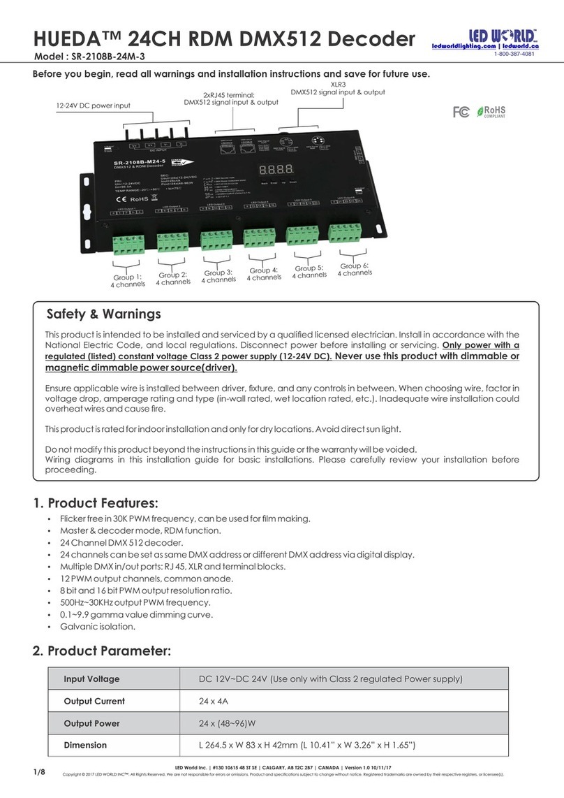
LED World HUEDA SR-2108B-M24-3 User manual

LED World

LED World HUEDA SR-2108B-M24-3 User manual

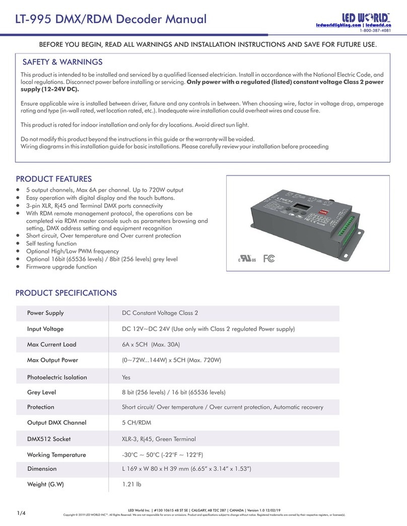
LED World LT-995 DMX/RDM User manual

LED World

LED World LT-995 DMX/RDM User manual

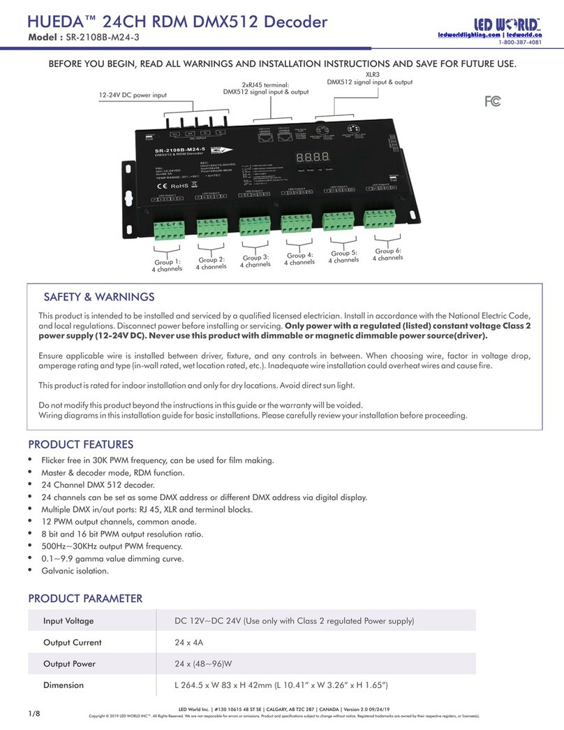
LED World HUEDA SR-2108B-24M-3 User manual

LED World

LED World HUEDA SR-2108B-24M-3 User manual

Popular Media Converter manuals by other brands

Aurora Design SCRF-405A-NTSC manual

Aurora Design

Aurora Design SCRF-405A-NTSC manual

Lufft 8160.UANA operating manual

Lufft

Lufft 8160.UANA operating manual

Axxess AX-MLOC725 installation instructions

Axxess

Axxess AX-MLOC725 installation instructions

SEC America 700HS Series user manual

SEC America

SEC America 700HS Series user manual

DirectOut Technologies EXBOX.SG user manual

DirectOut Technologies

DirectOut Technologies EXBOX.SG user manual

Z3 Technology HE4K-DCK-10 Connection instructions

Z3 Technology

Z3 Technology HE4K-DCK-10 Connection instructions

SIIG RS-232 to Multi-Mode Fiber Optic Quick installation guide

SIIG

SIIG RS-232 to Multi-Mode Fiber Optic Quick installation guide

PS Audio NuWave DAC Owner's reference

PS Audio

PS Audio NuWave DAC Owner's reference

North Star Fluxio operating manual

North Star

North Star Fluxio operating manual

Teac UD-501 owner's manual

Teac

Teac UD-501 owner's manual

Bose Professional ControlCenter CV41 quick start guide

Bose Professional

Bose Professional ControlCenter CV41 quick start guide

Aurora Design SCRF-441M quick start guide

Aurora Design

Aurora Design SCRF-441M quick start guide

EtherWAN EL900 Series user guide

EtherWAN

EtherWAN EL900 Series user guide

Simplified Manufacturing AUDEX1 user manual

Simplified Manufacturing

Simplified Manufacturing AUDEX1 user manual

Seeed Grove - Mouse Encoder quick start guide

Seeed

Seeed Grove - Mouse Encoder quick start guide

JMC ANALOG/DVI2SDI/HDMI user manual

JMC

JMC ANALOG/DVI2SDI/HDMI user manual

Techly IDATA HDMI-SDI2 user manual

Techly

Techly IDATA HDMI-SDI2 user manual

MD mxion DMSA user manual

MD

MD mxion DMSA user manual

manuals.online logo
manuals.online logoBrands
  • About & Mission
  • Contact us
  • Privacy Policy
  • Terms and Conditions

Copyright 2025 Manuals.Online. All Rights Reserved.