INTRODUCTION
Thank you for having chosen our LED lighting
Unpack the device, inside the box you should find:
The fixture device
One power cable
One XLR connection cable
This manual
Please check carefully that there is no damage caused by
transportation. Should there be any problems, consult your dealer
and don’t install this device.
DESCRIPTION
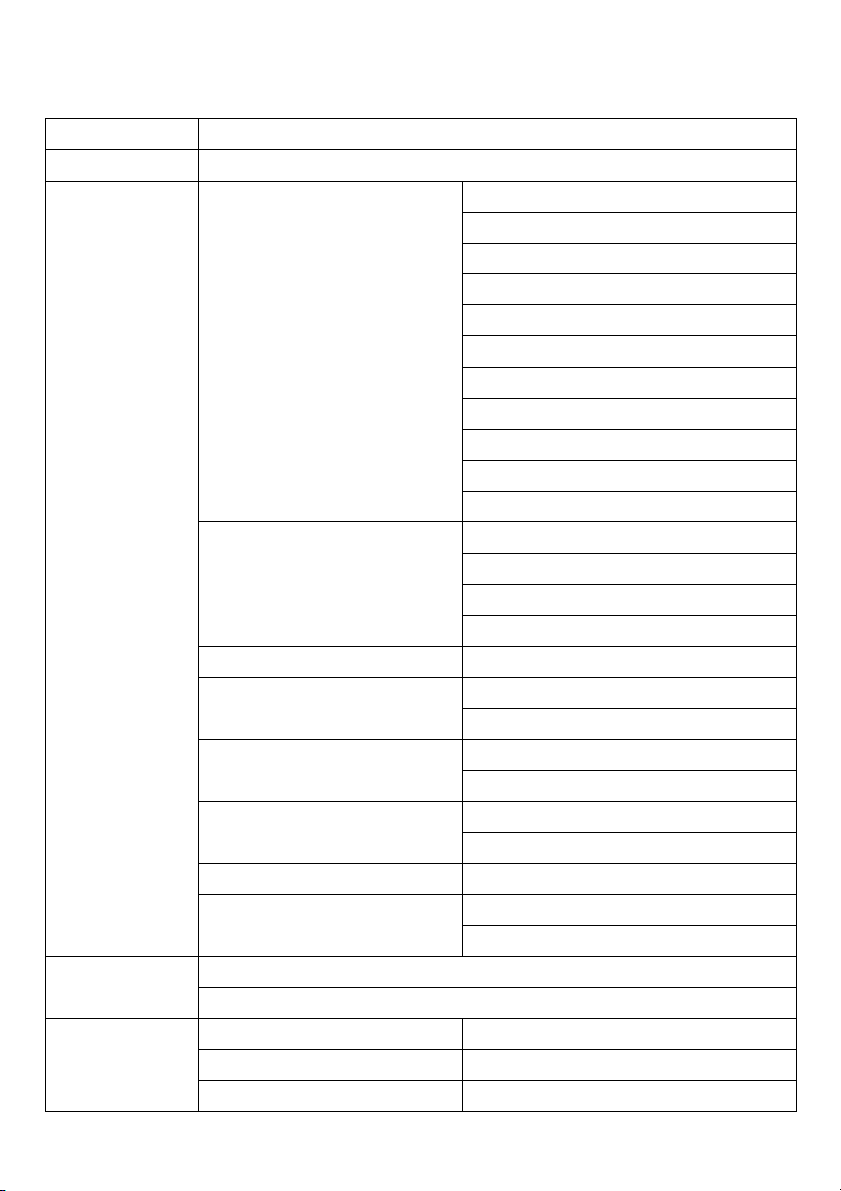
Features
Ÿ Easy multi fixture hanging system, outdoor version available
Ÿ 44pcs RGBW 4in1 LED, no ultraviolet radiation
Ÿ More than 50,000 hours for the LED light source
Ÿ 12,000 lm
Ÿ 35 degree / 25 degree lens
Ÿ 1/2/3/4/6/8/9/10ChF/10ChD/14/15 DMX channels
Ÿ 16 Bit Dimmer
Ÿ DMX Mode /Master-slave mode
Ÿ AC 100-240V 50/60Hz 300W
Ÿ Diecasting heatsink, convection cooling with silent fans
Ÿ With temperature sensor to extend the lamp life
Ÿ 7000 Hz LED scan rate
Ÿ L: 490mm H: 285mm W: 105mm, Weight 9Kg
l IP65/IP43 selectable
SAFETY INSTRUCTIONS
This device has left the factory in perfect condition. In order to
maintain this condition and to ensure a safe operation, it
is absolutely necessary for the user to follow the safety
instructions and warning notes written in this user manual.
This device falls under protection-class I. Therefore it is essential that
the device should be earthed.
The electric connection must carry out by qualified person.
If the external flexible cable or cord of this luminaire is damaged,
it shall be exclusively replaced by the manufacturer or his
service agent or a similar qualified person in order to avoid a hazard.