Legacy Empire User manual


1. Warranty
2. Our Commitment/Our Cabinetry
3. The Design of Empire
4. Specifications
5. Unpacking
6. Placement
6. Speaker Connections
7. Hook-Up Cables
8. The Amplifier
9. Bi-Amplification
11. For The Tweakers

1
Thank you for selecting a Legacy Loudspeaker System. These
hand-crafted instruments will provide you with many years of
listening enjoyment. Please take a few moments to read this brief
manual to insure maximum benefit from your speaker system.
Limited Ten Year Warranty
Legacy Audio, Inc. extends to the original owner coverage of
defects in materials and workmanship for a period of ten years
from the date of purchase.
This warranty does not include a) damage in shipment, b)
damage caused by accidental or intentional misuse or abuse, c)
units not registered with Legacy Audio, d) damage resulting from
unauthorized modifications or repairs. Liability is limited to the
repair or replacement, at our option, of any defective component
and shall not include property or consequential damages which
may result from the failure of this product.
If this product should ever require servicing, simply call
1-800-283-4644 for immediate assistance. Every Legacy speaker
system is completely modular and requires little more than a
Phillips screw driver and a soldering iron to service.
Customer Record
Model No. ____________________________
Serial No. _____________________________
Date of Purchase ____ / ____ / ____
Owner _______________________________
Street Address _________________________
City ______________ State _____ Zip _____

2
Our Cabinetry
The Empire front baffle is constructed with a 1 1/2” ultra
light medium density fiberboard.The baffle is milled using a
computer numerically controlled (CNC) machine.The baffle then
goes through multiple processes by hand until finishing. the
baffle and base receive nine coats of various finishes with hand
sanding between coats.The baffle and base then receive an
external skin through a process known as a “heat and pressure
lamination.” This involves a synthetic membrane heated to
increase its elasticity. Pressure differential is used to vacuum form
the membrane to the contours of the Empire baffle and base.
Please Note: Due to the nature of the material,Windex®or other
non-abrasive cleaners should be used to polish the finish.
Our Commitment
A great deal of forethought, love and satisfaction is instilled
into each piece of Legacy workmanship.We take pride in coming
to know many of our customers on a first name basis.
Your purchase of this product is backed by the renowned
“Legacy Satisfaction Guarantee”. We continue to stand behind it
with a solid ten year warranty, more than twice the industry
standard.

3
EMPIRE
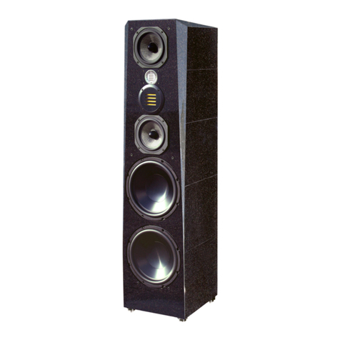
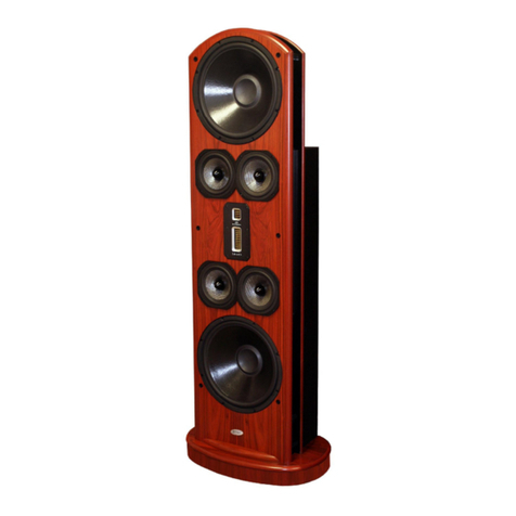
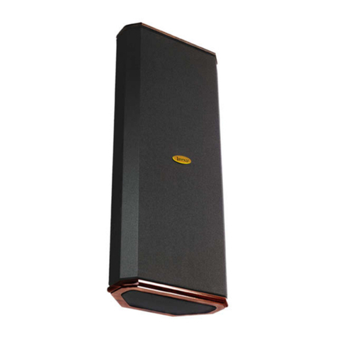
EMPIRE, the cornerstone of the MANHATTAN SYSTEM, is designed for how
we live. Several years ago, LEGACY AUDIO set the audio world on its ear with the
introduction of the Whisper speaker system.Whisper’s full-range, controlled
directivity design provided more clarity than any speaker to date. EMPIRE is
derived from this acclaimed technology.
EMPIRE IS UNIQUE.
EMPIRE looks unlike other speakers and sounds unlike other speakers.An
elegant 4.5’ tower, EMPIRE will grace your living room and give you thousands
of hours of enjoyment listening to your favorite music and videos.
EMPIRE is an “open air” design with dispersion analogous to the pick-up
pattern of the world’s finest microphones. Unlike other speakers that suffer
from enclosure resonances, EMPIRE will never sound “boxy,” because there is
no box.
With 50 lbs. of magnet structure, EMPIRE can start and stop more accurately
than conventional speakers.This reveals the natural contrast between loud and
soft sounds.
EVOLUTIONARY DESIGN
The design of EMPIRE posed some unique engineering challenges.
A new material called KEVLITE-Ti™ (comprised of KEVLAR™, Graphite, and
Titanium) was developed for our 5.25” drivers to bestow the “breath of life” on
vocals, and impart a rich luster to the glow of brass.
A special magnetic material called Neodymium was employed to lend
crystalline clarity to our NEOdome™ tweeters. A magnet made of
Neodymium is more than ten times stronger than conventional magnets.
To convey the treble in the most open and diffraction-free manner, this
ferro-fluid cooled, NEOdome tweeter was mounted in free air, equi-distant
from each midrange, and concentric to the 12” midwoofer.
A conventional woofer alignment simply would not suffice. Such alignments
would lag behind the pace set by the upper range drivers. Fortunately, Legacy
thinking is never limited by convention.
Bill Dudleston and his team developed a special 12” tri-woofer
configuration fortified with i-damp, a circuit which prevents uncontrolled
cone motion or “overshoot.”
Enhancing the transient characteristics of EMPIRE aids the listener in other
ways. Subtle ambient cues and low level details previously masked now
become apparent. Listener fatigue is greatly reduced, even after lengthy
listening sessions.
LEGACY’Sexhaustive research regarding room interaction enabled us to
specify a more optimal directivity pattern.The resulting improvement in
clarity is remarkable, even to the novice.
EMPIRE is designed to direct sound across the living room, minimizing
unwanted reflections from the side-walls and floor.This broadening of the
“sweet spot” allows everyone to enjoy a proper soundstage even when seated
off axis.
AN ARCHITECTURAL ACHIEVEMENT
EMPIRE’Selaborate baffle and base are machined from a 1.5” thick slab of
Ultra-LITE.This material is much more rigid than MDF, yet allows EMPIRE’S
weight to remain practical.
To further enhance Empire’s elegant design the high luster, black lacquer
finish is trimmed with solid, hand-finished Rosewood.

4
Specifications
System Type: 6 driver, 4 way.
Tweeter: 1” NEOdome.
Midrange: (2) 5.25” KEVLITE-Ti.
Midwoofer: 12” carbon/cellulose.
Woofer: (2) 12” carbon/cellulose.
Low Frequency Alignment: Open air i-damp configuration.
Sensitivity: 95 dB @ 2.83 V/1m.
Frequency response: 38 Hz - 25 kHz +/- 2 dB.
Crossover frequency (Hz): 80, 400, 3k.
Recommended Amplification: 10 - 400 watts/channel.
Impedance: 4 ohms.
Dimensions: 54” H x 13”W x 10” D
Weight: 100 lbs.

5
These next few pages are provided to aid in unboxing and
the setup of your Empire loudspeakers.
Your Empire loudspeakers are packaged very carefully and
shipped in two separate packages:
If any shortages or damages have occurred, notify us immediately
at 800-283-4644.
Unpacking the Empire
Please read this completely before beginning to unpack your
speakers.Although it is possible for one person to successfully
unpack the Empire two will make it much easier.Tools you will
find useful:
Phillips screw driver (cordless electric is best)
Utility knife
Begin with removing the cardboard boxes:
1. Lay boxes horizontally.
2.With the utility knife cut along the tape to open the bottom
box flaps.
3. Open all four flaps, fold the flap closest to the floor
underneath the box.
4. Stand speaker up so that speaker is standing right side up
and the open portion of the box is on the bottom. All 4 flaps
should be visible outside the box on the floor.
5. Carefully lift the cardboard box up and off of the internal
wood packaging frame.
6. Once the box is removed, remove the screws at each
corner that connect the wood planes on top and bottom to the
2 x 4’s.
7. Once the 2 x 4’s are removed lay the speaker on its back.
8. Remove the foam base from the bottom.
9. Stand speaker back up.
10. Remove foam cap from top of speaker
11.Then carefully lift center foam piece up and off of the
speaker.
Now that the Empires are unpacked and the boxes are out of the
way, you should position your speakers. No need to unpack the
other items as they will just be in your way. Resist the temptation
to install the grills or cones until the speakers are positioned
where you want them.

Placement of Empire
Positioning Empire for good performance is quite a bit easier
than for most speakers. Remember that Empire is actually an
dipole with a highly controlled directivity pattern. Corner
placements are actually quite workable though not necessarily
optimal. Empire will not become “boomy” like a conventional
system and it will not interact strongly with the sidewalls of your
room.
Simple guidelines:
1.You may position the Empire speakers farther apart than most
other speakers.This will help to acoustically shadow the head
properly and maintain better channel separation. Experiment
with what works best in your room.
2.Toe In: In most circumstances crossing speaker axes just
behind the listener’s head works best.This will broaden your
sweetspot horizontally. If dispersing into an “L” shaped seating
arrangement, you might find the best results by aiming the left
speaker at the right-most seating position, and the right speaker
at the left-most speaker position.
3. Hearing natural ambience present in recordings while
minimizing effects from your room favors a listener position that
is no farther from the plane of the speakers than the geometric
width of your room. More simply, if the room is 16 feet wide,
then sitting closer than 16 feet will allow you to hear more of the
recording and less of your room.
Speaker Connections
At the rear of each of your loudspeakers you will find a terminal
plate housing two rows of jumpered binding posts. The upper
row is the input to the “satellite” portion of the speaker. The
lower row is the input to the “bass” portion of the speaker.When
left in place, the factory-installed jumper bars allow the speaker
to be driven with a single channel of amplification. If biamping,
or biwiring, be sure to remove the jumper bars. More on this
later!
Connect each channel of your amplifier to a loudspeaker via
the five-way gold binding posts provided. Dual banana plugs or
gold plated spade lugs are recommended means for termination.
Be sure that you observe polarity when making the
connections.The positive (+) terminal of the amplifier should be
connected to the positive terminal of the loudspeaker.The
negative (-) terminal of the amplifier should be connected to the
negative terminal of the loudspeaker.
6

Hook-up Cables
The ideal conductor would have negligible resistance,
inductance and capacitance. The table below shows how a few
actual speaker cables measure up.
Cable Ωs/ft pF/ft µH/ft
12 ga. 0.0033 24 0.21
14 ga. 0.0048 17 0.13
16 ga. 0.0079 16 0.18
18 ga. 0.0128 28 0.21
Capacitance is considered insignificant in each cable because
its effect is well out of the audio bandwidth; inductance can be
decreased (at the expense of increased capacitance) by keeping
the conductor pair closely spaced.
How long would a cable have to be before inductance effects
would impinge on the audio spectrum? Approximately 300 feet
of 12 gauge would be required to establish a corner frequency of
20 kHz with an 8 Ohm loudspeaker. As you see, inductance is
not a problem for most of us.
What about phase shift due to frequency dependent travel
times down the speaker cable? Measurements show that 100 Hz
waves will be delayed about 20 billionths of a second behind 10
kHz waves when traveling to the end of a 10 foot speaker cable.
Since the cilia of the ear requires 25,000 times longer than this
just to transmit phase information, phase shifting is obviously not
the primary concern when considering speaker cables.
What about resistance? Finally we are getting somewhere.
Resistance is the controlling factor of the amplifier/loudspeaker
interface.
Excessive resistance can cause major shifts of speaker
crossover frequencies. The lower the impedance of the
loudspeaker, the greater the effects of series resistance. A run of
20 feet of 18 gauge can cause up to 10% deviations of crossover
center frequencies. That same 20 feet can undamp your damping
factor and reduce your systems’ output by one-half decibel.
The best way to approximate the ideal would be to keep
loudspeaker leads as short as is practical.
Our recommendation is the Legacy Transmission Line Cable.
Transmission Line is available in ready made 10 ft. runs or custom
lengths are available as well. Please call the factory at 1-800-283-
4644.
7

The Amplifier
Ideally the loudspeaker would be among the first
components selected when assembling a playback system. This
would allow the user to choose an amplifier capable of delivering
adequate amounts of current into the frequency dependent load
presented by the loudspeaker. However, when upgrading a
system, audiophiles may find themselves matching their new
loudspeakers to their existing amplification. For this reason,
extensive measures have been taken to ensure that each Legacy
speaker system represents a smooth, non-reactive load to virtually
any amplifier.
Often there is much confusion regarding amplification and
loudness levels. It should be understood that the role of the
amplifier goes beyond that of driving loudspeakers to a given
sound pressure level. The amplifier should be able to CONTROL
the loudspeakers across the entire music spectrum. This means
that parameters such as damping factor (values greater than 60
are acceptable) and dynamic headroom should not be overlooked
when comparing amplifiers.
How much power will your new speakers need? That
ultimately depends on your listening environment and musical
tastes. As little as five watts per channel should drive them to a
level satisfactory for background music. A typical 45 watt per
channel receiver may fill a room with the compressed mid-band
energy of “heavy metal,” but seem to lack weight or control with
classical recordings. Some audiophiles feel that 200 watts per
channel is the bare minimum to avoid audible clipping distortion
when reproducing music at “live” playback levels. Your Legacy
speakers are designed to take advantage of “high-powered”
amplifiers, so don’t be afraid to put them through their paces.
How much is too much power? Rarely is a drive unit
damaged by large doses of music power. More often than not the
villain is amplifier clipping distortion. Even through decades of
refinement, loudspeakers are still notoriously inefficient
transducers, requiring huge amounts of power to recreate the
impact of the live performance. Typically less than 1% of
electrical power is converted into acoustic output. For example,
an omni-directional transducer with an anechoic sensitivity of 90
dB @ 1w/1m has a full space efficiency of only 0.63%. When an
amplifier is unable to fulfill your loudspeakers demands, a
damaging harmonic spike may be leaked to the high frequency
drivers.
Another important point regarding loudness is that the dB
scale is a logarithmic one. This means that a 150 Watt amplifier
will potentially sound only twice as loud as a 15 Watt amplifier.
If all of this discussion of power and loudness seems a bit
abstract, consider the the example to the left:
The average acoustical power
developed by a person speaking in
a conversational tone corresponds
to a mere 0.00001 Watts. The
power that would be developed by
the entire population of the city of
New York speaking at once would
barely illuminate a single 100
Watt light bulb.
8
9
Biamplification
Your Legacy speakers offer the options of conventional wiring,
biwiring, passive biamplification or active biamplification. The
following is a summary of these options.
CONVENTIONAL WIRING
This format is the simplest way to connect your loudspeakers to
your amplifier. A single twin-conductor cable is used to link the
loudspeaker to a single channel of amplification. Jumper wires must
be left in place on the loudspeaker.
BIWIRING
Biwiring allows one to minimize the cable losses between the
amplifier and the loudspeaker. This is accomplished with a single
stereo amplifier by running separate sets of cables to the satellite
section and the subwoofer section from the same channel of
amplification.
This technique allows one to “play” with wire parameters a bit
(such as heavy gauge wire on the sub sections and light gauge solid
core on the satellites).
When biwiring, the use of gold spade lugs or dual banana plugs
can make the task much easier and safer than bare wire connections.
Again, the major reasons for biwiring over conventional wiring are
greater power transfer (improved efficiency) and tighter control over
the drivers (better damping).
PASSIVE BIAMPING
This option can yield even better results than biwiring due to
broader distribution of power requirements.
Passive biamplification allows low frequency current demands to
be routed to a separate channel of amplification, thus reducing strain
on the satellite amplifier and preventing subwoofer back-EMF from
modulating with the upper frequencies. There are two types of
passive biamplification;Vertical biamping (which requires two
identical stereo amplifiers or four monoblocs) and Horizontal
biamping (which does not require identical amplifiers).
1. Vertical Biamping
Vertical biamplification requires the dedication of a single stereo
amplifier for the left speaker, and another stereo amplifier for the
right speaker. This configuration improves channel separation and
can improve imaging slightly. If your preamp does not have two sets
of left/right outputs, you will need a pair of Y-adapters or a signal
splitter, such as a dual amp balancer, which will also allow adjustment
of subwoofer/satellite input levels.

2. Horizontal Biamping
Any two stereo amplifiers may be utilized in horizontal
biamplification. Many audiophiles prefer the "sweetness" of tubes on
the satellite portion of the loudspeaker while favoring the "control
and weight" of solid state amplifiers on the subwoofer section.
The biggest drawback of such a marriage of amplification is that
the two amplifiers may have different input sensitivities or output
polarities. Differences in the input sensitivities may be overcome by
using a dual amp balancer. This unit allows independent balancing of
the left subwoofer/satellite ratio and right subwoofer/satellite ratio.
It's also a good idea to check the owner's manuals to establish if
the amplifiers are inverting or non-inverting. If the two amplifiers are
of opposite polarity, then you should reverse the polarity at the inputs
of either the subwoofer or satellite binding posts.
NOTE: The above only applies to loudspeakers that incorporate the
subwoofer and satellite section in a single enclosure. It does not
apply towards the separate powered subwoofer/satellite configuration.
You must always observe the polarity when connecting the speaker
wire to a powered subwoofer.
ACTIVE BIAMPING
This option requires the utilization of an electronic (powered)
external crossover. Active biamplification is the most appealing
means of interfacing a subwoofer/satellite system due to the control
possibilities offered, but can also be the most costly.
An active crossover is inserted between the preamplifier outputs
and the inputs of two stereo amplifiers. Vertical or horizontal
biamping considerations are also applicable here.
A well designed active crossover will offer the user independent
high pass / low pass turnover frequencies for optimally blending the
satellites with the subwoofer sections of the speaker system. Other
features usually found are separate level controls for the high pass or
low pass sections and a choice of inverted or non-inverted low
frequency outputs (needed when strapping an amplifier to mono).
Also helpful is bass equalization and subsonic filtering.
When cascading active filters with the existing passive filters
within the speaker system, be sure to allow for adequate frequency
overlap. For instance, if the passive crossover is set at 500 Hz, select a
low pass corner frequency of 600 Hz and a high pass corner
frequency of 450 Hz to prevent a suck-out in the response at 500 Hz.
The controlled distribution of power afforded by the active
crossover results in less amplifier strain (better clarity), greater
dynamics, and lower intermodulation distortion. However, a basic
understanding of crossover slopes and crossover frequencies within
your loudspeaker will be needed to implement the active crossover
successfully.
10

11
For the Tweakers
Your Legacy loudspeaker is a true reference monitor designed
to reproduce all program material with an absolute minimum of
coloration. Occasionally we encounter a customer who simply
has a characteristic sound that he or she desires to achieve.
Rather than take on the close-minded position that this customer
is wrong an simply has one oar in the water, we would prefer to
offer our assistance.
We have found that the human ear is incredibly sensitive in
the range of 3 kHz. In fact, at some listening levels the ear is as
much as 15 dB more sensitive than at neighboring frequencies.
Therefore, a peaky studio microphone may occasionally raise the
hair on one’s neck. (One needs only to listen to the Stereophile
microphone test CD to find out just how bad some microphones
really are).
It seems that the presence band of 3 kHz to 8 kHz effectively
dictates the degree of forwardness, depth, detail, brightness, or
sweetness of a recording. Because of the sensitivity of this range,
we allow you some small adjustment.
The rear panel switch located near the binding posts may be
placed in the “down” position to reduce brightness in this region.
Mid Treble
Reduction
Switch
Down position
provides 2 dB of cut.
Table of contents
Other Legacy Speakers System manuals

Legacy
Legacy Focus User manual

Legacy
Legacy Phantom User manual

Legacy
Legacy FOCUS SE User manual

Legacy
Legacy Broadway User manual

Legacy
Legacy Marquis HD User manual

Legacy
Legacy FOCUS XD User manual

Legacy
Legacy Silverscreen II User manual

Legacy
Legacy Whisper XDS User manual

Legacy
Legacy Sconce Surround User manual

Legacy
Legacy Skyline User manual

Legacy
Legacy Expression User manual

Legacy
Legacy Xtreme XD User manual

Legacy
Legacy Phantom User manual

Legacy
Legacy Victoria LE User manual

Legacy
Legacy V System Operation manual

Legacy
Legacy VALOR User manual

Legacy
Legacy Harmony Center User manual

Legacy
Legacy Whisper XD User manual

Legacy
Legacy Studio HD User manual

Legacy
Legacy FOCUS SE User manual