2
• Boîtiers batteries
Deux procédures différentes sont possibles, pour installer/changer les
boîtiers batteries des ASI et des Trimod® BATTERY. Lire attentivement
toutes les consignes suivantes avant d’intervenir sur l’appareil.
Les boîtiers batteries doivent toujours être ajoutés/remplacés par
multiples de 4 (1 KB).
Nota: si la procédure d’installation/substitution a modifié le nombre
total de KB installés dans l’ASI, il est nécessaire de mettre à jour
l’instauration des KB par l’intermédiaire du panneau frontal.
Après avoir conclu les opérations indiquées ci-dessus, il est conseillé
d’effectuer une calibration de la batterie, de manière à obtenir des
indications précises concernant l’autonomie totale de l’ASI.
Si l’ASI dispose globalement de plus d’1 KB pour chaque 10kVA de
puissance fournie en sortie, il est possible de substituer les boîtiers
batteries 1 KB à la fois avec ASI On-line.
Cette opération peut être effectuée aussi bien sur l’ASI Trimod® que
sur les BATTERY Trimod®. Nous vous rappelons qu’1 KB est formé
de 4 boîtiers batteries
La procédure de substitution est la suivante:
1. S’assurer que l’ASI ait installé au moins 1KB tous les 10kVA de
puissance fournie en sortie plus un;
2. S’assurer que l’ASI n’est pas en train de marcher à batterie et que
le chargeur de batterie est en état de maintenance ou en veille.
Pour vérifier l’état du chargeur de batterie, entrer dans le menu État
ASI -> Mesures -> Batteries, et vérifier la quatrième ligne affichée à
l’écran.
3. Extraire les 4 boîtiers batteries relatifs à un seul KB.
4. Introduire les 4 nouveaux boîtiers batteries et les fixer avec les vis
fournies avec l’appareil;
5. Répéter les pas 2, 3 et 4 pour chaque KB à installer/remplacer.
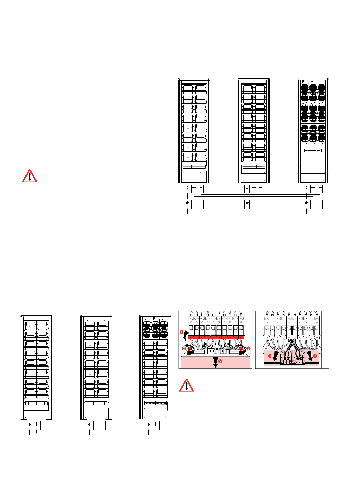
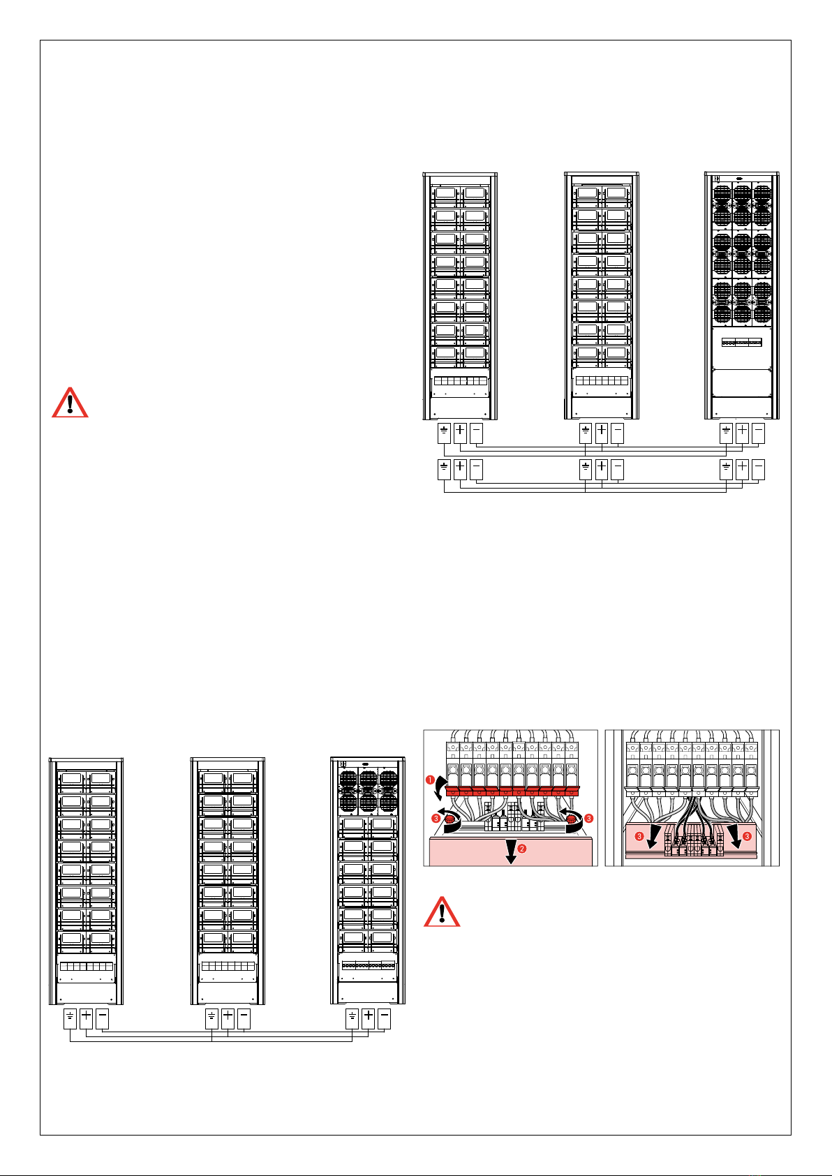
• Valeurs fusibles batterie recommandées pour ASI Trimod® BATTERY
• Valeurs fusibles batterie recommandées pour ASI Trimod® BATTERY/2
• Valeurs fusibles batterie recommandées pour ASI Trimod® BATTERY (1x94Ah)
Dans le cas d’un ajout simple de KB, il suffit d’effectuer les étapes
décrites aux points 2, 4 et 5.
ATTENTION
Ne substituer qu’1 seul KB à la fois
Note: si l’ASI passe à batterie pendant l’exécution de l’opération, s’arrêter
et ne pas extraire ni introduire de boîtiers batteries! Il est possible de
reprendre l’opération quand l’ASI recommence à fonctionner On-line.
Note: si au cours de l’opération, l’alimentation d’entrée venait à
manquer, l’autonomie serait réduite: il faut donc tenir compte de cette
possibilité avant de commencer.
Installation/substitution des boîtiers batteries avec ASI en by-pass
de maintenance.
Cette procédure est valable pour tous les modèles d’ASI Trimod® et
sur les Trimod® BATTERY.
ATTENTION
En by-pass de maintenance, la charge est alimentée
directement par le secteur en entrée.
1. Pour mettre l’ASI en modalité de by-pass de maintenance, exécuter
les pas de 1 à 8 décrits au paragraphe 9.3.1.
2. Extraire les 4 boîtiers batteries relatifs à un seul KB. Pour ajouter un
KB, n’enlever aucun boîtier batterie;
3. Introduire les 4 nouveaux boîtiers batteries et les fixer avec les vis
fournies avec l’appareil;
4. Répéter les pas 2, 3 et 4 pour chaque KB à installer/remplacer.
5. Exécuter les pas de 1 à 6 décrits au paragraphe 9.4.2 pour mettre
l’ASI de l’état de by-pass de maintenance à l’état On-line.
En cas de simple ajout de KB, il suffit d’effectuer les opérations
décrites aux points 1, 3, 4, et 5.
PUISSANCE FUSIBLE DE BATTERIE
Trimod® BATTERY 4KB
F B+ F B-
10/15/20/30/40/60 kVA N.4 - 50A 500V gG (14 x 51) N.4 - 50A 500V gG (14 x 51)
PUISSANCE FUSIBLE DE BATTERIE
Trimod® BATTERY/2 5KB
F B+ F B-
10/15/20/30/40/60 kVA N.5 - 50A 500V gG (14 x 51) N.5 - 50A 500V gG (14 x 51)
PUISSANCE FUSIBLE DE BATTERIE
Trimod® BATTERY (1x94Ah)
F B+ F B-
10 kVA N.1 - 50A 500V gG (22 x 58) N.1 - 50A 500V gG (22 x 58)
15/20 kVA N.1 - 100A 500V gG (22 x 58) N.1 - 100A 500V gG (22 x 58)
30 kVA TT/TM N.2 - 80A 500V gG (22 x 58) N.2 - 80A 500V gG (22 x 58)
40 kVA N.2 - 125A 500V gG (22 x 58) N.2 - 125A 500V gG (22 x 58)
60 kVA N.3 - 100A 500V gG (22 x 58) N.3 - 100A 500V gG (22 x 58)