manuals.online logo
Brands
  1. Home
  2. •
  3. Brands
  4. •
  5. LEGRAND
  6. •
  7. Marine Radio
  8. •
  9. LEGRAND Bticino HD4607/4 User manual

LEGRAND Bticino HD4607/4 User manual

This manual suits for next models

6

Popular Marine Radio manuals by other brands

Garmin GTX 45R installation manual

Garmin

Garmin GTX 45R installation manual

Garmin GTX 33 installation manual

Garmin

Garmin GTX 33 installation manual

Thrane&Thrane TT-6222A VHF DSC user manual

Thrane&Thrane

Thrane&Thrane TT-6222A VHF DSC user manual

Vesper Cortex HV1 installation guide

Vesper

Vesper Cortex HV1 installation guide

Thrane&Thrane Sailor RT5022 VHF DSC manual

Thrane&Thrane

Thrane&Thrane Sailor RT5022 VHF DSC manual

Saab R5 SUPREME AIS Operation & installation manual

Saab

Saab R5 SUPREME AIS Operation & installation manual

West Marine VHF580 owner's manual

West Marine

West Marine VHF580 owner's manual

Garmin VHF 315 Series installation instructions

Garmin

Garmin VHF 315 Series installation instructions

Barco MDSC-2226 user guide

Barco

Barco MDSC-2226 user guide

West Marine VHF490 owner's manual

West Marine

West Marine VHF490 owner's manual

GME GX800 instruction manual

GME

GME GX800 instruction manual

Garmin VHF100 - 25W VHF RADIO Declaration of conformity

Garmin

Garmin VHF100 - 25W VHF RADIO Declaration of conformity

Uniden UM425 VHF DSC owner's manual

Uniden

Uniden UM425 VHF DSC owner's manual

Kongsberg cNODE MiniS LF instruction manual

Kongsberg

Kongsberg cNODE MiniS LF instruction manual

Trig Avionics TT26 installation manual

Trig Avionics

Trig Avionics TT26 installation manual

West Marine VHF500 owner's manual

West Marine

West Marine VHF500 owner's manual

Siemens SIMATIC RTLS4060T manual

Siemens

Siemens SIMATIC RTLS4060T manual

Cobra Marine MARINE MR HH330 FLOAT owner's manual

Cobra Marine

Cobra Marine MARINE MR HH330 FLOAT owner's manual

manuals.online logo
manuals.online logoBrands
  • About & Mission
  • Contact us
  • Privacy Policy
  • Terms and Conditions

Copyright 2025 Manuals.Online. All Rights Reserved.

1
1
4
2
6
5
7
3
1
02'
=
$8;
1
02'
=
$8;
1
02'
=
$8;
1
02'
=
$8;
HD4607/4
HC4607/4
N4607/4
L4607/4
NT4607/4
AM5787/4HS4607/4
Description
This device is used to arm, disarm, and separate the zones of the system by placing a
transponder badge (item 3530S and item 3540 previously stored in the central unit) in
front of the zone transponder badge receiver.
When used in an automation system it performs the control function for the management
of scenarios.
By pressing one of the pushbuttons, the corresponding zone is armed/disarmed.
Within four seconds from the last pressure, the separation performed must be conrmed
by moving a transponder saved in the central unit close to the device.
Should this not take place, then the previous condition is automatically restored. Red LEDs
on indicate that the zones are active, whereas red LEDs o show that they are disarmed.
Conguration
BURGLAR-ALARM mode:
Since this item belongs to the activator group, it needs to be set up with the number of
the“group”assigned and the progressive number of the devices in the“group”. It can also
be programmed to perform Automation functions (scenario management).
See Automation“MY HOME”guide for details.
Z
This congurator assigns the number of the appropriate zone (from 1 to 8) in the“group”
of devices (any free zone in the system). To congure it as belonging to the activator
group, no congurator must be inserted.
N°
This congurator assigns the progressive number within the group of activators.
Congurator 1 identies the rst device, congurator 2 identies the second, and so
forth, up to a maximum of 9 activators (dividers, expanders or activators).
NOTE: If all 9 permitted devices have already been assigned to the activator group,
it could be possible to assign to congurator Z (zone it belongs to) a value between
1 and 9, taking into account the progressive number.
MOD
It assigns the modes of the audible signals (BEEP) and luminous signals (LED ON)
provided by the divider when controlled by the transponder; it is used as a activators/
disconnector of the“Burglar-alarm”system.
Technical data
- Power supply from SCS BUS: 27 Vdc
- Max. absorption: 15 mA
- Operating temperature: 5 – 40°C
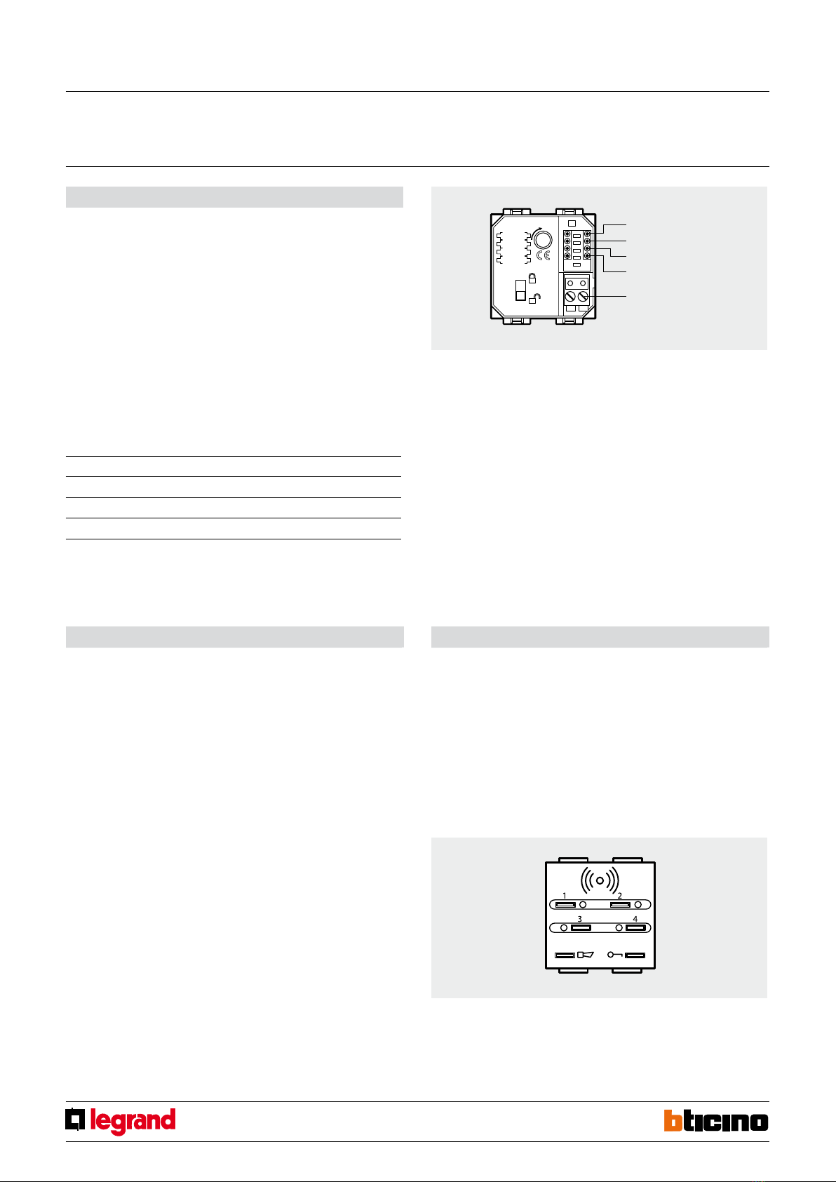
Legend
1 - Transponder badge receiver zone;
2 - LED and pushbutton for controlling of zone 2;
3 - LED and pushbutton for controlling of zone 4;
4 - Indication“System ON/OFF”;
5 - Alarm warning;
6 - LED and pushbutton for controlling of zone 3;
7 - LED and pushbutton for controlling of zone 1.
Dimensional data
Size: 2 modules
AUX
Position not congurable for the“Burglar-alarm”function; congure only if it is necessary
to enable the device for Automation functions (management of the scenarios stored in
the unit or scenario module).
Front view
Z
No.
MOD
AUX
Clamp for burglar
alarm BUS
Rear view
Central unit
used
Congurator
value
LED ON Enabling
BEEP
3486
3485/B
HD/HC/HS/L/N/
NT4601
none YES YES
1 NO YES
2 YES NO
3 NO NO
L/N/NT4600/1
A/AM5780/1
4 YES YES
5 NO YES
6 YES NO
7 NO NO
1-4 zone transponder
divider
MQ00028-c-EN 24/04/2014
2
1
02'
=
$8;
1
02'
=
$8;
1
02'
=
$8;
1
02'
=
$8;
HD4607/4
HC4607/4
N4607/4
L4607/4
NT4607/4
AM5787/4HS4607/4
Conguration
AUTOMATION mode – SCENARIO MANAGEMENT:
Z
This congurator with value 0-9 coincides with the A position of the scenario module.
N°
This congurator with value 1-9 coincides with the PL position of the scenario module.
MOD
Assigns the operating mode. Connect congurator 9.
AUX
It assigns one of the scenarios programmed on the scenario module to the four
pushbuttons (SCE = 1-9) as per the table.
Pairing transponders
1.
Move the“programming block”switch to the open padlock and then:
2. Press pushbuttons 1 and 4 at the same time for more than 5 seconds until the alarm
LED status comes on for 0.5 second and an audible signal is heard.
3. Release pushbuttons 1 and 4.
4. Move the transponder being programmed close to the device:
- if the transponder has been correctly saved the alarm status LED will slowly ash
twice and an audible signal will be heard. Go to step 6.
- if the code is already in the memory there will be 2 audible signals and the led will
ash quickly twice.
- if the memory is full there will be 5 audible signals and the LED will ash quickly 5
times.
5. To store other transponders repeat the procedure in step 4, otherwise go to step 6.
6. Move the “programming block” switch back on the closed padlock to exit
programming. Otherwise the device will exit programming mode after 1 minute of
inactivity.
Erasing the memory
1. Move the“programming block”to the open padlock.
2. Press pushbuttons 1 and 4 at the same time for more than 10 seconds and check that
the LED ashes slowly 4 times, and that there is an audible signal.
3. Release pushbuttons 1 and 4.
4. The transponder zones activator will remain in programming mode, ready for a new
programming sequence.
5. Move the switch back to the closed padlock position to exit the erasing procedure.
Z
No.
MOD
AUX
Clamp for burglar
alarm BUS
Pushbutton no. Associated scenario no.
pushbutton 1 SCE
pushbutton 2 SCE + 1
pushbutton 3 SCE + 2
pushbutton 4 SCE + 3
Example
If congurator 3 is connected to AUX, use pushbutton 1 to recall scenario no. 3, pushbutton
2 to recall scenario no. 4, pushbutton 3 to recall scenario no. 5, and pushbutton 4 to recall
scenario no. 6
1-4 zone transponder
divider
MQ00028-c-EN 24/04/2014