Sonardyne um-8370 User manual

Sonardyne International Limited
Blackbushe Business Park
Yateley, Hampshire
GU46 6GD United Kingdom
T. +44 (0) 1252 872288
F. +44 (0) 1252 876100
E. support@sonardyne.com
W. www.sonardyne.com
920-0005
UM-8370
User Manual for the Type 8370
WSM 6+ Transponder
Issue A Rev 1
Issue Date: 28 May 2015

User Manual for the Type 8370
WSM 6+ Transponder
UM-8370
Issue A Rev 1
ii
This user manual is the copyright and intellectual property right of Sonardyne International Limited
(“Sonardyne”) and is provided solely for the customer’s use of the Sonardyne equipment as
described in this user manual and in accordance with Sonardyne’s then prevailing terms and
conditions of sale. This user manual has been compiled to the best of Sonardyne’s knowledge and
belief, but no representation, warranty (whether express or implied) or guarantee is made to any
persons or legal entities as to the accuracy, reliability or completeness of the information contained
in this user manual.
This user manual contains the proprietary, confidential information of Sonardyne and other third
parties and as such may not be used, disclosed or placed in the public domain (by whatever means)
by the customer except expressly in accordance with and subject to the above referenced terms
and conditions of sale.
The copyright and any and all intellectual property rights of any and all third parties which may be
referenced in this user manual or which may have provided proprietary products and/or software
and/or documentation (in whatever format) to Sonardyne in respect of the Sonardyne equipment as
described in this user manual is hereby duly acknowledged.
The Sonardyne equipment described in this user manual is protected by UK Patent No. 2415113,
US Patent No. 8,139,442 and other patents internationally. 6G®and Sonardyne Wideband®are
registered trademarks of Sonardyne International Limited.
© Sonardyne International Limited 2015. All rights reserved.

User Manual for the Type 8370
WSM 6+ Transponder
UM-8370
Issue A Rev 1
iii
Contacting the Sonardyne Support Team
24-hour Emergency Telephone Helpline: +44 (0) 1252 877600
The Sonardyne 24-hour helpline is answered at the UK Headquarters during normal office hours
(08:00 to 17:00). Outside these hours, your call is automatically transferred to an agency, which logs
the details of your emergency and alerts the appropriate Sonardyne personnel.
Our aim is to make sure emergency requests are dealt with immediately during office hours, and are
responded to within 30 minutes at all other times.
Please note the helpline is for emergency use only.
If you require non-emergency product support, please contact your nearest Sonardyne office.
Alternatively, contact the Sonardyne Head Office:
Sonardyne International Ltd
Blackbushe Business Park
Yateley
Hampshire
GU46 6GD
United Kingdom
Telephone: +44 (0) 1252 872288
Fax: +44 (0) 1252 876100
Email: [email protected]
Note
Email and telephone support is available during normal UK office hours (08:00 to 17:00).

User Manual for the Type 8370
WSM 6+ Transponder
UM-8370
Issue A Rev 1
iv
Contents
Contacting the Sonardyne Support Team.................................................................................. iii
Amendment History.................................................................................................................... vii
Section 1 – Introduction ............................................................................................................... 1
1.1 Scope of this Manual ............................................................................................................. 1
1.2 Purpose of this Manual .......................................................................................................... 1
1.3 Related Publications .............................................................................................................. 1
1.4 Conventions........................................................................................................................... 1
Section 2 – Safety ......................................................................................................................... 2
2.1 Introduction............................................................................................................................ 2
2.2 Safety Procedures ................................................................................................................. 2
2.2.1 Warnings .................................................................................................................... 2
2.2.2 Cautions..................................................................................................................... 3
Section 3 – Technical Description ............................................................................................... 5
3.1 Introduction............................................................................................................................ 5
3.2 WSM 6+ Types ...................................................................................................................... 5
3.3 Endcap .................................................................................................................................. 6
3.4 Connectors ............................................................................................................................ 7
3.4.1 Standard .................................................................................................................... 7
3.4.2 Remote External Release Variant .............................................................................. 7
3.5 Housing Labelling .................................................................................................................. 7
3.5.1 Manufacturing Data .................................................................................................... 7
3.5.2 Serial No. ................................................................................................................... 7
3.5.3 Config......................................................................................................................... 7
3.5.4 Transducer Type ........................................................................................................ 8
3.5.5 Housing Rating........................................................................................................... 8
3.5.6 UNIT ID ...................................................................................................................... 8
3.5.7 ADDRESS.................................................................................................................. 8
3.6 Operation............................................................................................................................... 8
3.7 Functionality .......................................................................................................................... 9
3.8 Configuration ......................................................................................................................... 9
3.9 Battery and Charger ............................................................................................................ 10
3.9.1Type ......................................................................................................................... 10
3.9.2 Charging Description................................................................................................ 10
3.9.3 Fast Charging Feature.............................................................................................. 10
3.9.4 Deeply Discharged Battery....................................................................................... 11
3.9.5 Pressure Relief Vent Valve....................................................................................... 12
Section 4 – Installation ............................................................................................................... 13
4.1 Introduction.......................................................................................................................... 13
4.2 Pre-Use Checks................................................................................................................... 13
4.2.1 Checking the Pressure Relief Vent Valve ................................................................. 13
4.2.2 Charging the Battery ................................................................................................ 14
Section 5 – Operation ................................................................................................................. 16
5.1 Introduction.......................................................................................................................... 16
5.2 Operational Modes .............................................................................................................. 16
5.2.1 Transponder Mode ................................................................................................... 16
5.2.2 Responder Mode...................................................................................................... 16
5.3 Configuring the WSM 6+...................................................................................................... 16
5.3.1 6G Terminal Lite....................................................................................................... 17

User Manual for the Type 8370
WSM 6+ Transponder
UM-8370
Issue A Rev 1
v
5.3.2 iWAND handheld Test Unit....................................................................................... 17
5.4 Preparing the WSM 6+ for use............................................................................................. 17
5.4.1 Check the Pressure Relief Vent Valve...................................................................... 17
5.4.2 Charging the Battery ................................................................................................ 17
5.4.3 Setting the Address .................................................................................................. 17
5.4.4 Power and Gain Configuration.................................................................................. 17
5.4.5 Navigation Mode Configuration ................................................................................ 17
5.4.6 Pulse Position Depth Aiding ..................................................................................... 17
5.5 Location on ROV ................................................................................................................. 17
5.6 Electrical Connections ......................................................................................................... 18
5.7 WSM 6+ Pre-Deployment Checklist..................................................................................... 18
5.8 After Use ............................................................................................................................. 19
Section 6 – Maintenance ............................................................................................................ 20
6.1 Introduction.......................................................................................................................... 20
6.2 Retrieval from the Water ...................................................................................................... 20
6.3 Dismantling.......................................................................................................................... 20
6.4 Inspection ............................................................................................................................ 20
6.5 Lubrication ........................................................................................................................... 20
6.5.1 Subconn and Micro-Subconn Connectors ................................................................ 20
6.6 Corrosion Removal .............................................................................................................. 21
Section 7 – Functional Testing .................................................................................................. 22
7.1 Introduction.......................................................................................................................... 22
7.2 Test Equipment ................................................................................................................... 22
7.2.1 6G Terminal Lite....................................................................................................... 22
7.2.2 iWAND Hand Held Test Unit..................................................................................... 22
7.3 Connecting the WSM 6+ to a PC ......................................................................................... 22
7.4 Functional Tests .................................................................................................................. 23
7.4.1 Serial Communications Test..................................................................................... 23
7.4.2 Transponder Test ..................................................................................................... 23
7.4.3 Responder Test........................................................................................................ 23
7.4.4 Sensor Test.............................................................................................................. 24
7.4.5 Release Test ............................................................................................................ 24
7.4.6 Battery Check........................................................................................................... 24
7.4.7 Firmware Update...................................................................................................... 24
7.4.8 Test Report .............................................................................................................. 25
Section 8 – Fault Diagnosis ....................................................................................................... 26
8.1 Introduction.......................................................................................................................... 26
8.2 Fault .................................................................................................................................... 26
8.2.1 Transponder Doesn’t Reply to Interrogations or Commands .................................... 26
8.2.2 Transponder Replies to Commands, but not to Interrogations .................................. 27
8.2.3 Transponder Replies to Commands, but Telemetry Errors are Detected.................. 27
8.2.4 Battery Life is Shorter than Expected ....................................................................... 27
Section 9 – Retrieval and Storage ............................................................................................. 28
9.1 Introduction.......................................................................................................................... 28
9.2 Retrieval .............................................................................................................................. 28
9.3 Storage................................................................................................................................ 28
Section 10 – Spares.................................................................................................................... 30
10.1 Introduction.......................................................................................................................... 30
Section 11 – Technical Specifications....................................................................................... 31
11.1 Technical Drawings ............................................................................................................. 31
11.2 Pin-Out Wiring Connections................................................................................................. 32

User Manual for the Type 8370
WSM 6+ Transponder
UM-8370
Issue A Rev 1
vi
11.2.1 Standard Housing Wiring Connections ..................................................................... 32
11.2.2 External Remote Release Option Wiring Connections.............................................. 33
11.3 Specifications for Type 8370-1111 & 8370-4112 WSM 6+................................................... 34
Appendix A – Frequency Tables............................................................................................ 36
A.1 HPR 400 Frequency Table .................................................................................................. 36
A.2 Sonardyne Wideband Frequency Table............................................................................... 36
Definitions ................................................................................................................................... 38
Figures
Figure 3-1 Type 8370-1111 Omni-Directional Wideband WSM 6+ .............................................6
Figure 3-2 Type 8370-4112 Directional Wideband WSM 6+ ......................................................6
Figure 3-3 Type 8370-1111 Omni-Directional WSM 6+ Endcap.................................................6
Figure 3-4 Charger/Comms Connections.................................................................................11
Figure 4-1 WSM 6+ Pressure Relief Vent Valve ......................................................................13
Figure 4-2 WSM 6+ Battery Charging Connections..................................................................15
Figure 7-1 WSM 6+ to PC Connection Configuration ...............................................................22
Figure 11-1 Type 8370-1111 Omni-Directional WSM 6+ Outline Drawing................................31
Figure 11-2 Type 8370-4112 Directional WSM 6+ Outline Drawing .........................................31
Figure 11-3 5-Way Connector Pin Out and Mating Tail ............................................................32
Figure 11-4 8-Way Connector Pin Out and Mating Tail ............................................................33
Tables
Table 1-1 Related Publications ..................................................................................................1
Table 1-2 Conventions used in this Manual ...............................................................................1
Table 3-1 Configuration Identification Table...............................................................................8
Table 3-2 WSM 6+ Configuration Options..................................................................................9
Table 5-1 WSM 6+ Pre-Deployment Checklist .........................................................................19
Table 9-1 Storage Conditions ..................................................................................................29
Table 10-1 Component Identification .......................................................................................30

User Manual for the Type 8370
WSM 6+ Transponder
UM-8370
Issue A Rev 1
vii
Amendment History
The amendment history records all amendments and additions made to this manual.
Issue Revision Date Comments Section Page
A 0 01-02-2015 Draft All All
A 1 28-05-2015 Initial Issue All All

User Manual for the Type 8370
WSM 6+ Transponder
UM-8370
Issue A Rev 1
Section 1 – Introduction 1
Section 1 – Introduction
1.1 Scope of this Manual
This User Manual describes the safe installation and operation of the Wideband Sub-Mini 6+
(WSM 6+) Transponder / Responder. The information and procedures within this manual are based
on Sonardyne’s knowledge and experience.
1.2 Purpose of this Manual
This manual contains information for personnel involved in WSM 6+ system operations. It includes
technical information to configure, operate and maintain these systems, and specific information
concerning WSM 6+ products supplied by Sonardyne.
To make sure the safety of the installer and operator is maintained it is important that all warnings
and cautions in Section 2– Safety of this manual and in any related manuals are read and fully
understood.
1.3 Related Publications
To make sure the equipment is operated safely, a Sonardyne Safety Manual is supplied with this
user manual. It is important that the Sonardyne Safety Manual is read and fully understood before
proceeding with any activity on the equipment.
Table 1-1 Related Publications
Publication Title
Sonardyne Safety Manual Operational and Safety Precautions
UM-8300-099 User Manual for 6G Terminal Lite
UM-8315 User Manual for the Type 8315 iWAND
1.4 Conventions
Table 1-2 Conventions used in this Manual
Format Convention
Boldface Type User Input, Menu Options, Keys, e.g. Click OK
Arrow (>) Selection of an additional menu item e.g. File > Save
Italic Type References to Figures, Tables, Sections and other internal/external source

User Manual for the Type 8370
WSM 6+ Transponder
UM-8370
Issue A Rev 1
Section 2 – Safety 2
Section 2 – Safety
2.1 Introduction
Before any activity is carried out on the equipment, it is recommended that the included Sonardyne
Safety Manual and all warnings and cautions in this manual are read and fully understood.
It is recommended the operator complies with the Health and Safety Regulations applicable to the
vessel and the region before operating this equipment.
Operators and service personnel must be familiar with the normal operating and safety procedures
for subsea equipment.
Documentation must be consulted whenever a or warning symbol is found on the
equipment, in order to determine the nature of the potential hazard and any actions which must be
taken.
If any additional equipment is used, any warnings and cautions in the equipment user manual must
be read and fully understood.
If the equipment is used in a manner not specified by the manufacturer, the protection provided by
the equipment may be impaired.
The safety of any system incorporating this equipment is the responsibility of the assembler of the
system.
2.2 Safety Procedures
Before carrying out any procedure on the equipment, make sure that all of the following warnings
and cautions are read and fully understood.
2.2.1 Warnings
Personal protection. Appropriate protective equipment such as protective footwear, hard hat
and gloves must be worn when handling or carrying out any procedures involving Sonardyne and
other equipment.
Heavy equipment. Many Sonardyne products and equipment types, such as transponders,
transceivers, cable drums etc. require Manual Handling Equipment (MHE) for lifting due to their heavy
weight. If MHE is not available, it is the responsibility of the operator to perform a manual handling
risk assessment prior to carrying out manual lifting/handling. Refer to the individual equipment
documentation for weight specifications.
Dismanting. This transponder must only be accessed internally and dismantled by qualified
Sonardyne personnel.
Faulty battery pack. If a fault is suspected with the battery pack it must be investigated by
qualified Sonardyne personnel and should not be deployed.
Risk of toxic gases and Corrosive Liquids. Do not stand in direct line with the end of the
transponder when operating the Pressure Relief Vent Valve. Sudden release of high pressure gases
could cause injury to personnel. Wear Personal Protective Equipment such as goggles when
operating the Pressure Relief Vent Valve.
Risk of toxic gases. Make sure the work environment is well ventilated. Toxic gases may be
released when operating the Pressure Relief Vent Valve.

User Manual for the Type 8370
WSM 6+ Transponder
UM-8370
Issue A Rev 1
Section 2 – Safety 3
Hazardous substance. Molykote 44 is a mild irritant. When lubricating connector faces, Personal
Protective Equipment such as gloves and goggles must be worn.
Risk of burns. Do not carry out maintenance on the transponder if the housing is hot. Lower the
transponder into cold water and wait for the housing to cool. Wear Personal Protective Equipment
such as gloves.
2.2.2 Cautions
Battery power failure. Do not charge the battery packs in any way not outlined in this manual.
Failure to follow instructions may result in a loss of battery pack life or damage to the battery packs.
Damage to battery packs. Do not fast charge/discharge the WSM 6+ battery pack other than
when using the Type 8370-011-01 ( /-02 ) WSM 6+ comms/charger and WSM 6+ charger PSU.
Damage to battery packs. The WSM 6+ battery pack must only be charged using the Sonardyne
Type 8370-011-01 ( /-02 ) comms/charger unit and matching charger PSU.
Loss of current protection. Do not allow the transponder to be cooled or heated during the
charging process as the over current protection component characteristics may change adversely.
Equipment damage. Only use the authorised battery packs in the transponder. Failure to use the
correct batteries could cause damage to the equipment.
Equipment damage. Do NOT allow the transponder to be cooled or heated during the battery
charge level check or charging process.
Equipment damage. Do NOT continually connect the battery charger to the transponder if the
battery is fully charged as it will reduce its life and may cause damage.
Multiple beacon address Conflict. Do not operate multiple beacons on the same acoustic
address setting in the water at the same time. The address must be unique to any one beacon
operating in the same acoustic area.
Equipment damage. A standard Subconn non-shorting blanking plug must be fitted when
deployed if the connector on the unit is not being used.
Damage to external connector when submerged. The external connector must be covered while
the transponder is submerged, either by the protective dummy plug (part no. 312-6874) or by the free
plug of an external power cable.
Damage to connectors. The Subconn and Micro-Subconn connectors must not be mated
without lubrication as this will lead to delamination of the rubber from the connection pins and cause
connector failure.
Damage to connectors. Do not over apply grease to the connector faces as a build-up of grease
in the female connector will affect connector integrity.
Damage to connectors. Failure to clean sand or silt correctly could result in damage to the
connectors and O-ring seals.
Equipment damage. Failure to clean sand or silt from the connectors could result in the splaying
of the female contact and damage to the O-ring seals.


User Manual for the Type 8370
WSM 6+ Transponder
UM-8370
Issue A Rev 1
Section 3 – Technical Description 5
Section 3 – Technical Description
3.1 Introduction
The Wideband Sub-Mini Plus (WSM 6+) transponder/responder is designed for use with Sonardyne
Wideband Navigation Systems, SIMRAD “HPR” and Sonardyne LUSBL families of range-bearing
acoustic navigation systems. The WSM 6+ can be configured to any interrogation and reply setting,
and its command address can also be changed easily using the supplied PC software, 6G Terminal
Lite.
The WSM 6+ is a small rugged beacon targeted at USBL applications such as subsea vehicle
tracking or towfish tracking. It has an operating life of at least 3 days at 1 pulse/second (see Section
11.3 “Specifications”) when powered from the Nickel Metal Hydride rechargeable battery pack.
Alternatively, the WSM 6+ can be powered by an external DC supply for continuous operation.
An external switch allows disconnection of the power to preserve battery life between deployments.
In addition to these features, all WSM 6+ beacons are fitted with a depth sensor to offer depth-aided
navigation by sending dual, time-coded reply pulses to each interrogation, or report depth as a
telemetry reply.
Note
Dismantling of the WSM 6+ must only be carried out by Sonardyne qualified personnel.
3.2 WSM 6+ Types
The WSM 6+ available types are described below (see Section 3.8 “Configuration”):
•Type 8370-1111 – Omni-directional
•Type 8370-4112 – Directional
•Type 8370-1211 – Omni-directional, dual release support (voltage)
•Type 8370-4212 – Directional, dual release support (voltage)
•Type 8370-1411 – Omni-directional, dual release support (contact closure)
•Type 8370-4412 – Directional, dual release support (contact closure)
Omni-Directional (8370-1x11) variants (see Figure 3-1) have a maximum operating depth of 1000
metres, but this may be limited by the full scale depth of the pressure sensor. Directional (8370-
4x12) variants (see Figure 3-2) have a maximum operating depth of 4000 metres.
Types 8370-1211 and 4212 also provide two bi-directional voltage outputs via the endcap connector
for applications such as driving a motor release or burnwire. The output can provide up to a
maximum of 1A current, with the ability to configure the output duration ( up to 20 minutes ) and set
a trip or hold current.
Types 8370-1411 and 4412 also provide two contact closure outputs via the endcap connector.

User Manual for the Type 8370
WSM 6+ Transponder
UM-8370
Issue A Rev 1
Section 3 – Technical Description 6
Figure 3-1 Type 8370-1111 Omni-Directional Wideband WSM 6+
Figure 3-2 Type 8370-4112 Directional Wideband WSM 6+
3.3 Endcap
The connector endcap shields the electrical charging socket and ON/OFF switch. When not in use,
the unit should be switched OFF to preserve battery charge.
Note
The Nickel Metal Hydride batteries do self-discharge over a number of weeks so the WSM 6+
should always be fully charged before use.
Figure 3-3 shows the endcap for the Type 8370-1111 omni-directional WSM 6+ (Type 8370-4112 is
identical apart from a wider diameter and a DEPTH LIMIT 4000 m identification).
Figure 3-3 Type 8370-1111 Omni-Directional WSM 6+ Endcap
Depth Sensor cover plug 5 way connector MCBH5M for Comms / charging*
Pressure Relief Vent Valve ON/OFF rotary switch
*Refer to Section 11.2 “Pin-Out Wiring Connections”for connector pin details.

User Manual for the Type 8370
WSM 6+ Transponder
UM-8370
Issue A Rev 1
Section 3 – Technical Description 7
3.4 Connectors
The endcap connector allows a responder electrical trigger, RS232 communications to configure the
unit, a battery charging input and a separate external dc power input.
Note
Refer to Cautions in Section 2 – Safety “Damage to external connector when submerged”.
3.4.1 Standard
The standard 5-way endcap connector is a type Subconn Micro MCBH5M and mates with a
standard in-line connector type Subconn Micro MCIL5F.
3.4.2 Remote External Release Variant
The remote external release 8-way endcap connector is a type Subconn Micro MCBH8F and mates
with a standard in-line connector type Subconn Micro MCIL8M.
3.5 Housing Labelling
Waterproof labels on the housing uniquely identify the transponder as follows:
•MANUFACTURING DATA
Serial No. 123456-789
Config. 1111
Transducer MF Omni
Housing Rating 1000 m
•UNIT ID
•ADDRESS
3.5.1 Manufacturing Data
The manufacturing data details all essential information about the equipment that will be required if
it is necessary to contact Sonardyne International Limited.
3.5.2 Serial No.
The serial no. is the unique WSM 6+ identification number and should be quoted in all
communications with Sonardyne International Ltd and their agents.
3.5.3 Config
The Config number is a four digit number that identifies the depth rating, material, housing size and
transducer type.
e.g. Config: 4112
•4 = Depth rating 4000 m
•1 = Standard
•1 = Standard
•2 = MF Dir – Type 1

User Manual for the Type 8370
WSM 6+ Transponder
UM-8370
Issue A Rev 1
Section 3 – Technical Description 8
Table 3-1 Configuration Identification Table
Depth Rating Variant Housing Transducer Type
1 1000 m Standard Standard MF Omni
2 2000 m Voltage Out Max MF Dir – Type 1
3 3000 m Burn Out Mini MF Dir – Type 2
4 4000 m Contact Closure Midi MF Super Dir
5 5000 m Dunker LMF Omni
6 6000 m Remote LMF Dir
7 7000 m Sphere LF Omni
8 EHF Omni
9 Special
0 No Code
3.5.4 Transducer Type
The transducer identifies the type of transducer beam-shape fitted to the transceiver. The types of
transducer can be omni or directional.
3.5.5 Housing Rating
The housing limit is the normal pressure rating of the transceiver housing. The sensor endcap may
be rated less than the housing limit. Check the endcap label and use the lower figure.
3.5.6 UNIT ID
The UNIT ID box shows the unique identification number for the transceiver or transponder. The
UNIT ID number is required to upgrade the functionality of the transceiver of transponder. The UNIT
ID cannot be changed and is stored on the device.
3.5.7 ADDRESS
The address contains the acoustic identity of the transceiver or transponder. The acoustic address
is used by the transceiver to communicate with another transceiver or transponder. The first two
digits of the address define the family group and the last two digits of the address define the channel
number. The acoustic address can be changed using a secure acoustic or serial command, which
requires the UID of the transponder. It is important that the information on the address label is kept
up to date.
3.6 Operation
The WSM 6+ is designed to be operated in both transponder and responder modes. An electrical
trigger input pin is provided on the external connector to enable operation in responder mode.
The acoustic command address and the interrogation channel are given on a separate housing
label. These can be changed by software, via the RS232 link.
All Sonardyne wideband addresses are available as well as all HPR 400 channels. A full table of
frequencies for each valid navigation channel is given in Appendix A – Frequency Tables.
Acoustic commands can be used to reconfigure the transponder and to switch on depth aiding.

User Manual for the Type 8370
WSM 6+ Transponder
UM-8370
Issue A Rev 1
Section 3 – Technical Description 9
3.7 Functionality
Sonardyne's WSM 6+ offers wideband navigation replies which are capable of significant
improvements in ranging accuracy and repeatability, especially in responder mode. It also retains
compatibility with existing HPR and LUSBL range-bearing acoustic navigation systems. The
acoustic signal level transmitted by the Type 8370-4112 is strongest on axis and useful over a 90
degree cone. It is usually mounted with the transducer pointing upwards – typically for marking
small ROVs.
In circumstances where orientation in the general direction of the ship cannot be guaranteed, such
as for longer ranges in shallow water, the omni-directional response of the Type 8370-1111 omni-
directional transponder is recommended. The Type 8370-1111 has the same functionality as the
8370-4112 apart from depth rating and has a lower transmit acoustic source level on axis but a
wider omni-directional beam-pattern (±120°).
The WSM 6+ offers the following benefits to the user:
•High capacity nickel metal hydride rechargeable battery with at least 3 days operating life
at 1 pulse/second and rapid-charge capability by external connector.
•All “HPR 400” channels are supported.
•All Sonardyne wideband reply signals are supported giving better range accuracy and
repeatability.
•External connector for "Responder" mode trigger, external power supply, charger and
communications interface.
•ON/OFF feature via external switch.
•Acoustic commands to enable and disable the transponder and to enable the Depth Data
reply.
•Configured using 6G Terminal Lite software.
3.8 Configuration
The WSM 6+ configuration options are shown below:
Table 3-2 WSM 6+ Configuration Options
Type
Number
Transducer Depth
Rating
External Release
Option
Type Location
8370-1111 Omni-Directional Integral 1000 m
8370-1211 Omni-Directional Integral 1000 m Voltage
8370-1411 Omni-Directional Integral 1000 m Contact Closure
8370-4112 Directional Integral 4000 m
8370-4212 Directional Integral 4000 m Voltage
8370-4414 Directional Integral 4000 m Contact Closure

User Manual for the Type 8370
WSM 6+ Transponder
UM-8370
Issue A Rev 1
Section 3 – Technical Description 10
3.9 Battery and Charger
3.9.1 Type
The WSM 6+ is fitted with a 2000 mAh nickel metal hydride battery pack and must only be charged
with the Sonardyne Type 8370-011-01 (/-02 ) comms/charger unit and matching charger PSU.
Earlier types of transponder have different battery pack capacity, different rating AC power packs
and different versions of charger are not compatible with the WSM 6+.
3.9.2 Charging Description
A flat battery will charge for approximately 3 hours at the full rate of 1 A, during which the red Fast
Charge LED will illuminate. The charging current is applied to pin 3 of the external connector (zero
volts is pin 2). This charge time is considerably longer than the one-hour charge of the SSM. This is
due to the use of higher capacity NiMH cells in the WSM 6+, which cannot be charged at such a
high rate as the lower capacity cells in the SSM.
The charging current is controlled by electronics inside the transponder. When the battery reaches a
full charge the charging current is switched off, and the Fast Charge LED will switch off. However,
the charger also permanently supplies external power to the unit (28 V, 85 mA on pin 4) which will
trickle charge the unit and illuminate the yellow Trickle Charge LED. It is safe to leave the trickle
charge connected indefinitely.
3.9.3 Fast Charging Feature
The Fast Charge feature is controlled by electronics inside the transponder which monitors the
voltage and temperature of the battery pack to decide when to stop charging. The parameters are
first monitored some 14 minutes after connection so connecting the fast charger to a fully charged
battery will allow the full charging current to flow for that length of time.
Repeatedly connecting the fast charger to a fully charged (or near fully charged) battery will reduce
the life of the battery and may cause damage.
The charge control chip within the transponder will cut off charge current if:
•The rate of change of voltage with time indicates the pack is approaching full charge.
•The temperature of the pack rises outside limits (10–40ºC).
•A time limit is exceeded (in the WSM 6+ case this is three hours).
The current during fast charging is limited by the WSM 6+ PSU, not by the WSM 6+ charger/comms
unit.
If, in an emergency, it is necessary to charge the WSM 6+ by means other than the Type 8370-011-
01/02 dedicated comms/charger unit, then the charge supply should be 24 V at 1A constant current
for 2 hours maximum.
Note
The charging time must be reduced if the battery pack has been charged recently. The charging
current should be applied to pin 3 of the external connector with the return (zero volts) connected to
pin 2.
User Manual for the Type 8370
WSM 6+ Transponder
UM-8370
Issue A Rev 1
Section 3 – Technical Description 11
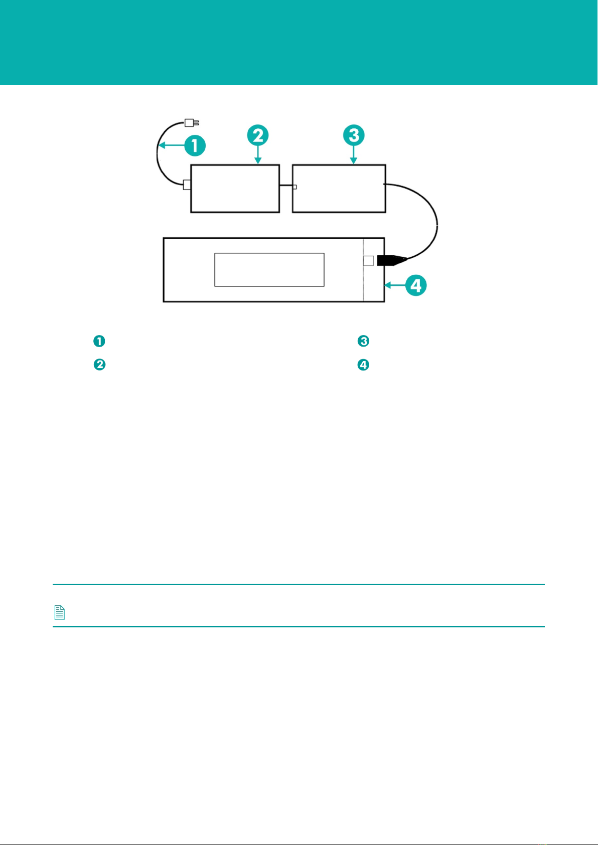
Figure 3-4 Charger/Comms Connections
AC cable option part numbers: UK 272-0345;
US 272-036C; Euro 272-0352 WSM 6+ Charger/Comms
WSM 6+ Charger PSU
WSM 6+
Various components inside the transponder are designed to limit damage due to misconnection of
the external signals. However, some damage to the electronic components may result. Under no
circumstances should mains AC power be applied to the transponder.
3.9.4 Deeply Discharged Battery
Special care must be taken if the battery has been allowed to become deeply discharged. In this
state it is possible for some cells to drop to near-zero voltage or even reverse the voltage on their
terminals. The WSM 6+ should always be switched off when not in use to minimise the chance of
entering this deep discharge state.
Once a cell has become deeply discharged, its capacity is reduced. This has the effect of
unbalancing the pack and therefore reduces the pack capacity. Usually the pack can be recovered
by fully re-charging. If not, then recovery can only be achieved by removing the pack and subjecting
it to several slow (200 mA) charge/discharge cycles. Even then the full capacity may not be
recovered.
Note
The battery pack must only be removed and replaced by qualified Sonardyne personnel.
Charging a pack which has suffered deep discharge can result in some gas being discharged by the
affected cells. If the pressure relief vent is found to be proud of its normal position, this may be an
indication that one or more cells have gassed and the appropriate action should be taken to recover
the battery pack as described above.

User Manual for the Type 8370
WSM 6+ Transponder
UM-8370
Issue A Rev 1
Section 3 – Technical Description 12
3.9.5 Pressure Relief Vent Valve
A Pressure Relief Vent Valve is provided to make sure there is no build-up of gas inside the
transponder caused by the charging process. The battery manufacturer recommends the batteries
are charged in an open environment. However, they also specify that no gas is vented by the
batteries, providing the recommended charging procedures are followed. The WSM 6+ includes
special circuitry to monitor the battery pack during charging. This safety feature makes sure the
battery cannot be overcharged in normal use. For this reason it is not deemed necessary to remove
the Pressure Relief Vent Valve during charging of a fully operational transponder.
Should there be any reason to suspect that there is pressure inside the unit, or that the charging
circuitry may be faulty, it is recommended the Pressure Relief Vent Valve is extracted prior to
charging (refer to Section 4.2.1 “Checking the Pressure Relief Vent Valve”) .

User Manual for the Type 8370
WSM 6+ Transponder
UM-8370
Issue A Rev 1
Section 4 – Installation 13
Section 4 – Installation
4.1 Introduction
Before installing the equipment, make sure Section 2 – Safety is read and fully understood.
4.2 Pre-Use Checks
Before installation, checks should be carried out to make sure the WSM 6+ is serviceable and ready
for use. These checks include:
•Check the Pressure Relief Vent Valve; refer to Section 4.2.1 “Checking the Pressure
Relief Vent Valve”.
•In necessary, charge the battery; refer to Section 4.2.2 “Charging the Battery”.
4.2.1 Checking the Pressure Relief Vent Valve
A Pressure Relief Vent Valve is provided to reduce the build-up of gas inside the WSM 6+ caused
by the battery charging process.
Check the Pressure Relief Vent Valve is flush with the endcap. If the Pressure Relief Vent Valve is
not flush it could indicate a pressure build-up during previous operations due to a fault developing in
the battery pack.
Note
Refer to Warnings in Section 2 – Safety “Faulty Battery Pack”.
Figure 4-1 WSM 6+ Pressure Relief Vent Valve
Pressure Relief Vent Valve
Table of contents
Other Sonardyne Marine Radio manuals


Popular Marine Radio manuals by other brands

Garmin
Garmin GTX 327 pilot's guide

Simons Voss Technologies
Simons Voss Technologies ALLEGION 3060 Series quick guide

EnerSys
EnerSys Alpha AlphaNet DOCSIS DM3X Series Technical manual

Becker
Becker ATC 2000 Installation and operation

Cobra Marine
Cobra Marine MARINE MR F45-D owner's manual

Garrecht Avionik
Garrecht Avionik VT-01 user manual


