manuals.online logo
Brands
  1. Home
  2. •
  3. Brands
  4. •
  5. LEGRAND
  6. •
  7. Smoke Alarm
  8. •
  9. LEGRAND tynetec ZXT811 User manual

LEGRAND tynetec ZXT811 User manual

Tynetec, a business unit of Legrand Electric Ltd
Cowley Road, Blyth Riverside Business Park, Blyth, Northumberland, NE24 5TF.
Tel: +44 (0) 1670 352371 www.tynetec.co.uk
Trusted Technology
Caring for People
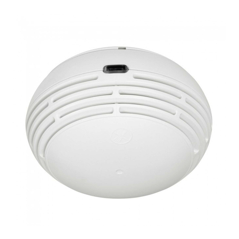
Heat Alarm
869MHz
Caring for People
_________________________________________________________________________
________________________________________________________________
Doc No. FM0823 V1.00 Page 1
•Compatible with Reach IP and Advent XT2
•Complies with BS 5446-2:2003
•Thermistek sensor technology
•10 year sealed for life Lithium battery (typical)
•Alarm point temperature range: +54oC to +62oC
•Alarm sound level: 85dB(A) @ 3m
•Large central Test/Silence ( ) button
•Operating Temperature: +4oC to +38oC
•Telecare Transceiver: 869.2125MHz Class 1.5
•Weight: 199 grams
•Dimensions: 132mm diameter x 60mm depth
•Product Code: ZXT811
Positioning
Heat alarms are best suited to areas where dust,
fumes and moisture can cause nuisance alarms in
smoke alarms such as; kitchens, laundry rooms, lofts
and garages. Heat alarms must be ceiling mounted in
the centre of the room. They should be at a distance
no greater than 5.3m from the farthest wall, no
greater than 5.3m from a door to any room in which
a fire might start and no greater than 5.3m from the
next heat alarm. Heat alarms should not be wall
mounted. Refer to the Manufacturer’s instruction
booklet for more information on positioning.
Thermistek technology activates the alarm sooner if
it predicts a significant rate of rise of temperature.
Alarm Condition
The unit will repeatedly sound 3 loud beeps and the
red light will flash every second. Check if there is a
fire hazard and leave the building.
DANGER: Never ignore any alarm. If you are not
certain of the cause, leave the building immediately.
Alarm Silence
In the event of a known false alarm you can
temporarily silence the heat alarm by pressing the
central Test/ button. The alarm will automatically
return to full sensitivity within 10 minutes.
Normal Operation
The red light will flash once every 45 seconds to
indicate normal operation.
Low Battery Condition
If the unit chirps every 45 seconds and the yellow
light flashes at the same time, this indicates the
battery is running low. The low battery condition will
also be reported automatically to the Alarm Receiving
Centre (ARC) or the local Manager. The complete
heat alarm should be replaced within 30 days.
Fault Condition
If the unit chirps every 45 seconds and the yellow
light flashes 20-25 seconds after, this indicates a fault
condition. Replace the heat alarm immediately.
Maintenance
Test the heat alarm once every week.
Clean once every 3 months using a vacuum cleaner
fitted with the soft brush attachment.
Do not use solvents or cleaners on the heat alarm,
the unit can be wiped with a damp cloth.
Disposal
Waste electrical products should not be disposed of
with normal household waste. The heat alarm is
ideally suited for disposal within the waste electronic
and electrical equipment (WEEE) recycling scheme.
Please recycle where facilities exist. Check with your
local authority or contact your supplier for
recycling/disposal advice.
Warning
The heat alarm contains a powerful Lithium battery.
If tampered with the battery may be damaged and
create a fire hazard. No attempt should be made to
open the case or remove the battery.
Tynetec, a business unit of Legrand Electric Ltd
Cowley Road, Blyth Riverside Business Park, Blyth, Northumberland, NE24 5TF.
Tel: +44 (0) 1670 352371 www.tynetec.co.uk
Trusted Technology
Caring for People
Heat Alarm
869MHz
Caring for People
_________________________________________________________________________
________________________________________________________________
Doc No. FM0823 V1.00 Page 2
The battery power
will now be switched
on and the red light
will flash once every
45 seconds to show
that it is active.
The unit will sound
an audible alarm
consisting of 2
cycles of 3 loud
beeps, then stop
automatically.
ZXT811
Ser No.
271799862
ISS A
ID: 88A200FE91
The Radio ID is a 10-digit
code printed on the radio
module label on the back
of the heat alarm
How to install the Heat Alarm
Make sure you have read and understood the
instructions on positioning the alarm before starting.
The base plate must be securely fixed to the ceiling.
Use the fixing slots on the base plate as a guide when
marking the position of the drill holes. Fix with the
screws and plugs provided.
Alternatively, the base plate can be fixed with the
self-adhesive pads provided. Ensure the surface is
smooth, clean and dry. Press hard to make sure the
self-adhesive pads are properly adhered.
Position the alarm on the base plate then twist it
clockwise until the alarm is fully locked in position.
WARNING: Removing the heat alarm from its base
plate will de-activate the unit and prevent it from
detecting heat.
How to test the Heat Alarm
Press the Test/ button in the centre and release.
The red light on the alarm will flash rapidly during
the audible signal. Do not test with a naked flame.
Telecare Radio ID
The heat alarm includes a plug-in radio transceiver
module to communicate with the Reach IP or XT2.
Registering the Heat Alarm onto a Reach IP
Login to Pulse CMP (www.tynetecpulse.com) and
enter the Reach IP Serial No. in the ALARM UNIT
view. Press the Accessories button and enter the
Radio ID code, Location and Equipment type.
Press Save then Synchronize.
Alternatively, with the Reach IP in normal operating
mode undo the fixing screw and remove the stand or
connector cover to access the ⚫Power button.
Press the ⚫Power button to enter Control Mode,
then press and hold the button until the unit
announces “add radio device” then release.
Press the ⚫button to confirm then activate the
alarm by pressing the Test button.
The Reach IP unit will sound a high beep if it’s a new
device and announce “range test mode”.
Press ⚫to confirm, or press to step to the next
function, or press to exit the mode.
Registering the Heat Alarm onto an Advent XT2
Radio Device Programming can only be performed
from the Advent XT2 Manager’s Panel designated as
the Controller. Login using the Manager or Engineer
password and touch the Programming button.
Select the Program Radio Devices option from the
Program Setting drop-down list.
Enter the Radio ID: this is the 10-digit code taken
from the radio module label on the back of the alarm.
Enter the Flat ID: this is the flat number the alarm is
being installed in. Enter 4-digits e.g. 0014.
Enter the Location: select where the alarm is located
from the drop-down list e.g. Kitchen.
Press the Send button to update the XT2 system.
⚫Power Button

Other LEGRAND Smoke Alarm manuals

LEGRAND Tynetec FireAngel ZXT810 User manual

LEGRAND

LEGRAND Tynetec FireAngel ZXT810 User manual

LEGRAND Tynetec Deaf Smoke ZXT487 User manual

LEGRAND

LEGRAND Tynetec Deaf Smoke ZXT487 User manual

LEGRAND 0 405 15 User manual

LEGRAND

LEGRAND 0 405 15 User manual

LEGRAND 0 405 17 User manual

LEGRAND

LEGRAND 0 405 17 User manual

LEGRAND tynetec ZXT819 User manual

LEGRAND

LEGRAND tynetec ZXT819 User manual

LEGRAND 643084 User manual

LEGRAND

LEGRAND 643084 User manual

LEGRAND 0333-CPD-292050 User manual

LEGRAND

LEGRAND 0333-CPD-292050 User manual

LEGRAND Tynetec FireAngel User manual

LEGRAND

LEGRAND Tynetec FireAngel User manual

LEGRAND 643087 User manual

LEGRAND

LEGRAND 643087 User manual

LEGRAND tynetec ZXT810 User manual

LEGRAND

LEGRAND tynetec ZXT810 User manual

Popular Smoke Alarm manuals by other brands

Quell Q2300 user manual

Quell

Quell Q2300 user manual

BRK electronic FG225 Manual Del Usuario

BRK electronic

BRK electronic FG225 Manual Del Usuario

VESDA VLP Maintenance Guide

VESDA

VESDA VLP Maintenance Guide

UTC Fire and Security DET-TRONICS U5005 instructions

UTC Fire and Security

UTC Fire and Security DET-TRONICS U5005 instructions

biosystems PhD Ultra Reference manual

biosystems

biosystems PhD Ultra Reference manual

Hochiki ESP FIREbeam installation manual

Hochiki

Hochiki ESP FIREbeam installation manual

FireAngel Thermoptek ST-622 manual

FireAngel

FireAngel Thermoptek ST-622 manual

American Sensor SA360 user manual

American Sensor

American Sensor SA360 user manual

Kidde KIR-PHD Installation sheet

Kidde

Kidde KIR-PHD Installation sheet

x-sense SCO6-W user manual

x-sense

x-sense SCO6-W user manual

System Sensor Innovair SSK451 quick start guide

System Sensor

System Sensor Innovair SSK451 quick start guide

Nittan Evolution EVC-DP instruction manual

Nittan

Nittan Evolution EVC-DP instruction manual

Xtrails VESDA VLI Product guide

Xtrails

Xtrails VESDA VLI Product guide

Tyco Electronics F08 Installation & programming manual

Tyco Electronics

Tyco Electronics F08 Installation & programming manual

Challenger SMART FORCE ASFSM Installation and operating instructions

Challenger

Challenger SMART FORCE ASFSM Installation and operating instructions

Pyromate P-45 manual

Pyromate

Pyromate P-45 manual

SenTech HK-21NZ installation instructions

SenTech

SenTech HK-21NZ installation instructions

Cordes CC-5RS instruction manual

Cordes

Cordes CC-5RS instruction manual

manuals.online logo
manuals.online logoBrands
  • About & Mission
  • Contact us
  • Privacy Policy
  • Terms and Conditions

Copyright 2025 Manuals.Online. All Rights Reserved.