LEGRAND XL3 S 160 Series User manual

THE GLOBAL SPECIALIST IN ELECTRICAL
AND DIGITAL BUILDING INFRASTRUCTURE
WORKSHOPSPECIFICATIONS
XL³ S 160
DISTRIBUTION CABINETS

DISTRIBUTION CABINET XL3S 160
XL³ S 160 cabinets are “fully modular” cabinets,
from 2 to 8 rows of 24 modules and from 4 to 8
rows of 36 modules supplied ready to use (rails
and multi-row faceplates mounted).
They are available in 2 metallic versions: surface
mounting and flush-mounting cabinets.
They can receive, modular devices, DPX³160, DRX
125 MCCBs and Vistop isolating switches up to
160A.
XL³ S 160 has been designed to make wiring and
connection easier with removable and adjustable
DIN rails.
It is supplied with multi-row faceplates.
LEGAL INFORMATION
Presentation pictures do not always
include Personal Protective Equipment
(PPE), but this is a legal and regulatory
obligation that must be scrupulously
respected.
In accordance with its continuous
improvement policy, Legrand reserves
the right to change the specifications
and illustrations without notice. All
illustrations, descriptions and technical
information included in this document are
provided as indications and cannot be held
against Legrand.

1
XL3S 160 WORKSHOP SPECIFICATIONS CONTENTS
CONTENTS
Safety instructions............................................. 2-3
Surface mounting cabinets
Preparing surface mounting cabinets ..............6 to 11
Mounting devices ................................................ 12-13
Wiring and connection........................................ 14-15
Accessories mounting ........................................ 16-17
Flush-mounting cabinets
Preparing flush-mounting cabinets............... 18 to 27
Mounting devices ............................................... 28-29
Wiring and connection....................................... 30-31
Accessories mounting ....................................... 32-33
Accessories and spare-parts.................... 34-35
WWW.LEGRAND.COM

2
SAFETY
INSTRUCTIONS
■Use only the products and accessories recommended by the Legrand Group in the catalogue, instructions, technical data sheets
and all other documents provided by Legrand (hereinafter referred to as «the Documentation») in compliance with the installation
rules.
■Improper installation and/or use may result in the risk of arcing in the enclosure, overheating or fire. The enclosures must be used
under normal conditions, they must not be subjected to Voltage / Current / Temperature values other than those specified in the
Documentation.
■Legrand declines all responsibility for any modification or repair of the equipment making up the enclosure that is not authorized by
the Legrand Group, as well as any failure to comply with the rules and recommendations specified by Legrand in the Documentation.
In addition, in the cases mentioned above, the warranty granted by Legrand will not be applicable.
■It is necessary to check that the characteristics of the products are appropriate for their environment and use during maintenance
operations, and to refer to the Documentation. If you have any questions or require clarification, please contact Legrand Group.
■The installation, use and maintenance of the enclosures and their components must be carried out by qualified, trained and
authorized personnel, in accordance with the regulations in force in each country.
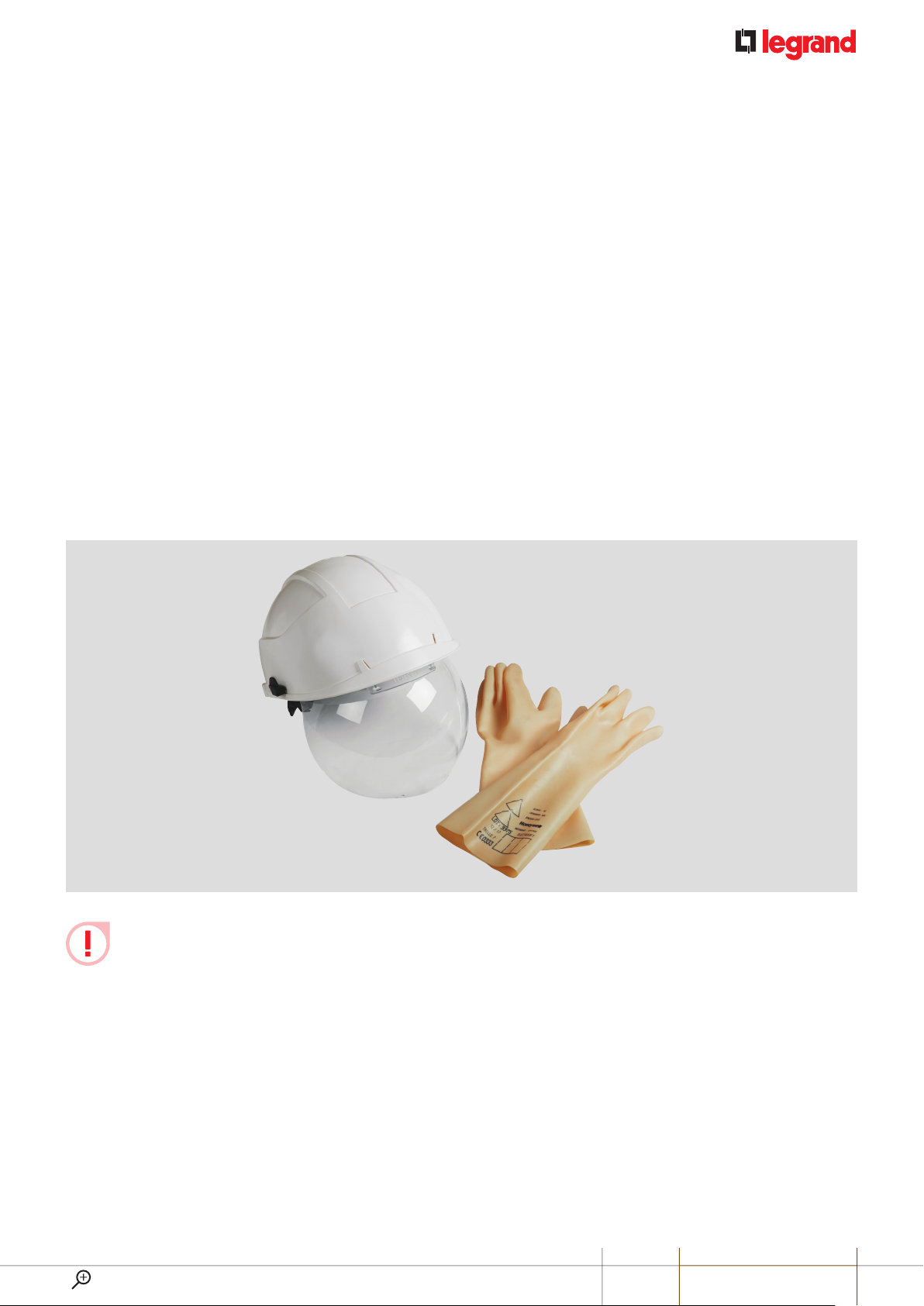
RISK OF ELECTRIC SHOCK, BURNS AND EXPLOSION.
■People working on the installation must have the appropriate electrical authorizations for the work to be carried out.
■Wear the PPE (Personal Protective Equipment) necessary to work on live products.
■Respect the safety rules related to electrical work.
■Improper electrical and mechanical use of equipment can be dangerous and may result in personal injury or damage to property.
■Depending on the maintenance operations to be carried out, partial or total power cuts of the enclosure concerned should be
planned before any work.
■When performing operations that involve access to the inside of the enclosure, be aware of the risk of burns before touching any
products or metal parts.
■Before turning the power back on, make sure that there are no foreign bodies and that all physical protections have been put back
in place (e.g.: screens, covers, shields).
General information

3
DISTRIBUTION CABINETSXL3S 160
Any failure to strictly apply the procedures and to respect these recommendations, could lead to serious risk of accident,
endangering people and property (in particular, without limitation, risk of burns, electric shocks, etc.).
The rules and recommendations in this document are based on our knowledge of the typical conditions of use of our
products in the fields of application usually encountered. However, it is always the customer’s responsibility to verify and
validate that Legrand products are suitable for its installation and use.
The customer must ensure proper installation, maintenance and operation of the equipment to avoid any risk of injury to personnel
or damage to property in the event of product failure, especially for applications that require a very high level of safety (e.g., those
in which the failure of a component may endanger human life or health).
The rules for storage, handling, installation and maintenance and the appropriate precautions and warnings must be strictly
observed and applied.
WWW.LEGRAND.COM

4
SURFACE MOUNTING
CABINETS
XL³ S 160 cabinets are ready to use cabinets with high capacity (up to 288 modules) and optimized dimensions for
electrical distribution up to 160 A.
They have been designed in order to simplify the protection equipment installation and the wiring operations.
- Adjustable DIN rail on 3 positions,
- Removable chassis,
- Flexibility in the choice of the terminal blocks.
SPECIFICATIONS
■Class I metal cabinet
■Rated peak withstand
current Ipk: 34 kA
■IP 30 without door, IP 40 with door
■IK 07 without door, IK 08 with door
■Door opening angle: 130°
■Conforming to standard IEC 61439-2
■Can take devices up to 160 A
■Colour RAL 9003
■Maximum rated voltage
(Ue) up to 500 V ±
■Rated insulation voltage:
(Ui) 1000 V ±
■Rated impulse withstand
voltage (Uimp):
8 kV (moulded case)
4 kV (modular)
■Supplied complete with rails,
multi-rows faceplates,
knock-out cable entry and
support for terminal blocks
(neutral and earth)
PRODUCTS SELECTION
The XL³ S 160 range contains “fully
modular” cabinets, from 2 to 8 rows of
24 modules and from 4 to 8 rows of 36
modules.
Possibility to choose a special col-
our from a panel of 197 shades:
RAL only possible on metal parts.
For any request on technical pos-
sibilities and extra costs, please
contact the technical support:
support-technique-edia.fr-lgs@legrand.fr

5
DISTRIBUTION CABINETSXL3S 160
THE XL³ S 160 SURFACE MOUNTING CABINET RANGE
24 MODULES PER ROW
Cat.Nos 3 372 02 3 372 03 3 372 04 3 372 05 3 372 06 3 372 07 3 372 08
Number of rows 2345678
Number of modules 48 72 96 120 144 168 192
Metal door (flat) 3 372 52 3 372 53 3 372 54 3 372 55 3 372 56 337257 337258
Glass door (flat) 3 372 72 3 372 73 3 372 74 3 372 75 3 372 76 337277 337278
36 MODULES PER ROW
Cat.Nos - - 3 372 14 3 372 15 3 372 16 3 372 17 3 372 18
Number of rows --45678
Number of modules - - 144 180 216 252 288
Metal door (flat) - - 3 372 64 3 372 65 3 372 66 337267 337268
Glass door (flat) - - 3 372 84 3 372 85 3 372 86 337287 337288
WWW.LEGRAND.COM

6
SURFACE MOUNTING CABINETS
The XL³ S 160 cabinets are supplied in
a cardboard packaging, reusable for
delivery to the site.
The cabinet is supplied with a bag
containing 2 screws to fix the terminal
block supports, 2 terminal block
supports, 4 blanking plates for keyhole,
8 covers (plugs) for joining /combination
and 4 caps for the hinge holes.
1DIMENSIONS
D = 135 mm
W
H
Useful depth: 102 mm
Cat.Nos H
(mm) Useful
HW
(mm) Useful
W
24
mod.
3 372 02 440 400
595 555
3 372 03 590 550
3 372 04 740 700
3 372 05 890 850
3 372 06 1040 1000
3 372 07 1190 1150
3 372 08 1340 1300
36
mod.
3 372 14 740 700
810 760
3 372 15 890 850
3 372 16 1040 1000
3 372 17 1190 1150
3 372 18 1340 1300
2FIXING
The XL³ S 160 surface mounting cabinets
can be fixed on a wall or a partition. This
can be realized with the internal fixing
points or with mounting lugs.
■Internal fixing
Each cabinet has 4 internal fixing points.
The shape of the knocked out holes is
used to attach and detach the cabinets.
1- Knock out the keyhole shaped holes.
2- Fix the cabinet by using 4 screws
(Ø 6mm minimum) and 4 washers.
In case of cabinet joining, it is
recommended to use the
mounting lugs (see page 7).
■Internal fixing centres
A
B
Cat.Nos A
(mm)
B
(mm)
24
mod.
3 372 02
350
297
3 372 03 447
3 372 04 597
3 372 05 747
3 372 06 897
3 372 07 1047
3 372 08 1197
36
mod.
3 372 14
566
597
3 372 15 747
3 372 16 897
3 372 17 1047
3 372 18 1197
Preparing the cabinets for use

7
DISTRIBUTION CABINETSXL3S 160
2FIXING CONTINUED
■Fixing with wall-mounting lugs
The wall-mounting lugs Cat.No 3 374 00
can be installed in horizontal or vertical
position.
1- Screw the lug in the required position
with the 2 screws + nuts supplied in
the pack.
View inside the cabinet:
2- Fix the cabinet on the wall by using
4 screws Ø 6mm.
■External fixing centres
Cat.Nos D
(mm)
C
(mm)
F
(mm)
E
(mm)
24
mod.
3 372 02 468
540
383
625
3 372 03 618 533
3 372 04 768 683
3 372 05 918 833
3 372 06 1068 983
3 372 07 1218 1133
3 372 08 1368 1283
36
mod.
3 372 14 768
756
683
841
3 372 15 918 833
3 372 16 1068 983
3 372 17 1218 1133
3 372 18 1368 1283
WWW.LEGRAND.COM

8
SURFACE MOUNTING CABINETS
3COMBINATION/JOINING KIT CAT.NO 3 374 07
The cabinets can be combined vertically
by using the kit Cat. No 3 374 04
composed of 4 screws and 4 nuts.
■Preparing
Knock out or cut the top/bottom of the
sides in order to insert the cables.
Knocked-out for cable gland.
Rectangular area.
■Fitting
Join the cabinets together by using the 4 screws + nuts provided in the kit
Cat.No337404. You might knock out the caps of the cabinets before joining.
NutScrew
Internal view of
the 1st cabinet
External view of
the 2nd cabinet
■Vertical assembly fixing centres
A = C + C
CC
BCat.Nos C
(mm)
B
(mm)
24
mod.
3 372 02 455
540
3 372 03 605
3 372 04 755
3 372 05 905
3 372 06 1055
3 372 07 1205
3 372 08 1355
36
mod.
3 372 14 755
756
3 372 15 905
3 372 16 1055
3 372 17 1205
3 372 18 1355

9
DISTRIBUTION CABINETSXL3S 160
4FACEPLATES MOUNTING
The XL³ S 160 are supplied with 1 or 2
faceplates (see the components in the
opposite table). The faceplates are fixed
on the cabinet with captive screws:
The plastic washer holds the screw on
the faceplate and makes the handling
easier.
The earth continuity between the
faceplate and the cabinet is pos-
sible thanks to a claw (see picture
below).
■Configuration by cabinet size
Cat.Nos Number of faceplates Number of fixing
points
24
modules
3 372 02 1 faceplate of
2 rows 4
3 372 03 1 faceplate of
3 rows 4
3 372 04 1 faceplate of
4 rows 6
3 372 05 1 faceplate of
5 rows 6
3 372 06 2 faceplates of
3 rows +
8
3 372 07
1 faceplate of
4 rows +
1 faceplate of
3 rows +
10
3 372 08 2 faceplates of
4 rows
+
12
36
modules
3 372 14 1 faceplate of
4 rows 6
3 372 15 1 faceplate of
5 rows 6
3 372 16 2 faceplates of
3 rows +
8
3 372 17
1 faceplate of
4 rows +
1 faceplate of
3 rows +
10
3 372 18 2 faceplates of
4 rows
+
12
WWW.LEGRAND.COM

10
SURFACE MOUNTING CABINETS
4FACEPLATES MOUTING
CONTINUED
■Fitting
For the installation of control and
signalling units or devices with a voltage
U>50 V on the faceplate, it is necessary
to add an equipotential link conductor
between the faceplate and the cabinet.
To achieve this, you must bend the
connecting lug of the faceplate with
pliers.
Connect the conductor (Cat.No 339753)
to the faceplate with a screw, a nut and 2
washers (not supplied) in order to ensure
the continuity.
The connection on the cabinet is made by
screwing a M6 nut (not supplied) on the
specified attachment points.
5SIGNALLING
As well as the label-holders on all
DIN rail mounting equipment and the
plastic marking strip Cat. No 0 203 99,
a clip-on holder accessory is available
for 24 modules (Cat. No 3 397 55) and
36 modules (Cat.No 339756).
6FITTING THE DOORS
The solid or glass doors can be fitted to
open to the left or the right (see selection
table page 5).
The slots for the hinges and the door
release are provided on both sides of the
cabinet.
Door kit components: 2 axis, 2 hinges,
1 handle up to 5 rows, 2 handles from
6rows,1keyand1crossboltand2 lipseals
■Finishes
To ensure the IP (Protection Index) of the
cabinet you must:
1- Clip the blanking keyhole (supplied
with the cabinet) on the side of the
hinges.
2- Seal the holes at the opposite of
the hinges (1 at the top and 1 at the
bottom) by using the caps supplied
with the cabinet.

11
DISTRIBUTION CABINETSXL3S 160
■Fitting the hinges
1- Fit and clip the hinges in the specified
slots on the door side.
2- Insert the axis of the hinge in the
specified hole.
3- Rotate the axis on 90° to lock the
system.
The axis should be properly clipped in
the specified location (see photo above).
■Fitting the handle
1- Fit and insert the handle in the hole at
the opposite of the hinges.
2- Insert the cross bolt at the back of the
handle, against the door.
3- Once the door released of the handle
installed, turn it with the key in lock position
in order to check the proper functioning.
Metal flat doors Cat.Nos 337257,
3 372 58, 3 372 67, 3 372 68 and
glass doors Cat. Nos 3 372 77,
337278, 337287, 337288 are equipped
with 2 handles.
The door axis are designed to be
and removed without tools. So the
door installation is made easier.
■Equipotential link
You have to make an equipotential link
if control and signalling units or devices
with voltage U>50 V are fitted on the door.
The doors are equipped with studs
for connecting the equipotential link
conductor Cat.No 339753.
1- Remove the dedicated plastic cover on
the cabinet (2 covers available). Then,
cut it to enable the cable to pass:
2- Put the plastic cover back in its
location, fit the cable on the stud of the
cabinet (with a M6 nut). Then, pass it
through the cover:
3- Remove the protection cover of the
earth stud on the door and fit the cable
end with the help of a M6 nut.
WWW.LEGRAND.COM

12
SURFACE MOUNTING CABINETS
Cabinets are delivered with the rails of
the chassis in the upper position, i.e.
ready to install the modular products
(MCB) as well as the Vistop < 160A.
The plug-in function of the chassis allows
the rails to be adjusted and the products
to be installed outside the cabinet, on a
workbench or other. Wiring can thus be
carried out in the workshop, at the same
time as the cabinet is installed on site.
To remove the chassis from the cabinet,
remove the 4 10 mm nuts (2 at the top
and 2 at the bottom):
To replace the chassis, it must be
inserted on the 2 lower studs and then
on the 2 upper studs. Tighten the 4 nuts,
starting with the 2 top ones:
Lower part
1DRX125 MOUTNING AVAILABLE
IN CERTAIN MARKETS
To install these products, it is necessary
to place the rail in an intermediate
position and install the DRX using the
corresponding adapters:
- Cat.no 0 271 87 for DRX 125 3P & 4P
- Cat.no 0 271 89 for DRX 125 1P
- Cat.no 0 271 90 for DRX 125 2P
Remove the rail by loosening the 2
screws with a Torx T30 end cap:
Twist both lugs 90° inwards:
Before
After
Replace the rail with the 2 screws in
the holes provided and then install the
product.
Modular devices (MCB) can be mounted
next to a DRX. To do this, use the rail
extension Cat.no 3 382 41. After cutting
it to length (if necessary), clip it onto the
omega rail next to the DRX.
The depth is then correct to allow the
faceplate to be fitted.
Mounting devices

13
DISTRIBUTION CABINETSXL3S 160
2DPX³ 160 MOUNTING
The rail must be placed in the low
position and the DPX³ must be equipped
with the corresponding adapters:
- Cat.no 4 210 68 for DPX³ 160 with side
motor drive
- Cat.no 4 210 71 for DPX³ 160 with no
side motor drive
- Cat.no 4 210 73 for DPX³ 160 with earth
leakage modules with no side motor
drive
Remove the rail by loosening the 2
screws with a Torx T30 end cap:
Twist both lugs (using pliers) outwards
as far as possible so as to fold them into
the uprights:
Before
After
Install the height kit Cat.no 3 374 07 on
both sides using the screws supplied
(take the fixing holes circled in red
below):
Kit Cat.no 3 374 07
Fixing holes
Kit installed on a side
Replace the rail with the 2 screws in
the holes provided and then install the
product.
Modular devices (MCB) can be mounted
next to a DPX³ 160. For this purpose,
the rail extension Cat.no 3 382 40 must
be used. After cutting it to length (if
required), it must be clipped onto the top
hat rail next to the DPX³.
The depth is then correct to allow the
faceplate to be fitted.
It is also possible to combine a
DRX 125 and a DPX³ 160 in the
same row by mounting the DRX
(with its adapter) on the extension Cat.no
3 382 42.
The rail must be in the low position (see
paragraph 2).
The mounting of the DPX³ 160 is detailed
in section 2.
WWW.LEGRAND.COM

14
1INSERTING OF THE CABLES/
CABLES ENTRY
The XL³ S 160 are fitted with knockout
cable entries in order to mount cable
glands ISO25 and/or ISO32:
- 24 modules: 14 entries Ø 25 and
7 entries Ø32
- 36 modules: 20 entries Ø 25 and
10 entries Ø32
Ø 32 mm
Ø 25 mm
Ø 32 mm
Ø 25 mm
It’salsopossibletocutrectangularareasto
allow the circulation of several cables.
The angles are pre-marked on the top
and at the bottom of the cabinet. The
cutting is done using a jigsaw or a tube
cutter.
Number
of
modules
Rectangular knockout
entries
Number and dimension
24 7 (62x80) mm
36 10 (62x80) mm
2PROTECTIVE CONDUCTORS AND IP
2X DISTRIBUTION TERMINAL BLOCKS
First, you need to fit the mounting lugs
which are supplied with the cabinet
(2lugs) by using the nuts.
Mounting
lug
Mounting nut
(tightening with a
10mm spanner)
The brass terminal block Cat.No 037300
can be fixed on the lugs supplied with the
cabinet (with the 2 screws and 2 nuts
supplied with the Cat.No 037300).
4 positions in the cabinets are possible.
→ 2 at the top and/or 2 at the bottom.
Here is example with 2 earth terminal
blocks at the top of the cabinet.
Wiring and connection
SURFACE MOUNTING CABINETS

15
DISTRIBUTION CABINETSXL3S 160
To make the wiring of the protective
conductors, it’s also possible to use one (or
more) copper bars Cat.No 037389 that you
have to cut. (Original length → 990 mm).
As the holes of the bar are threaded, the
mounting lugs are placed between the
copper bar and the screw heads (M5
screws, not supplied)
For the installation of an IP 2X distribution
terminal block, you need to use a flat bar
12x2mm Cat.No 004819. This bar is also
fixed on the lugs supplied with the cabinet.
You must cut and drill it, as follows:
Maximum lenght:
24 modules → maximum length 510 mm
36 modules → maximum length 726 mm
Fixing centres: 400 mm in 24 modules
cabinets and 616 mm in 36 modules
cabinets.
Drilling: Ø 5mm. Fixing screw: M5 + nuts
(not supplied).
400 mm55 55
510 mm
Example with 24 modules cabinet
Minimum lenght:
24 modules → minimum length 410 mm
36 modules → minimum length 630 mm
Fixing centres: 400 mm in 24 modules
cabinets and 616 mm in 36 modules
cabinets.
Drilling: Ø 5 mm. Fixing screw: M5 + nuts
(not supplied).
400 mm
410 mm
Example with 24 modules cabinet
IP 2X terminal blocks
2 additional 47 mm (maximum)
terminal blocks (IP 2X or bare)
Cat. Nos 0 048 20, 0 048 30,
004840 or 004850 can be fixed
on each side of the 12 x 2 mm flat bar,
when cut to the maximum length.
WWW.LEGRAND.COM

16
SURFACE MOUNTING CABINETS
BLANKING PLATES
5 MODULES CAT.NO 001660
24 MODULES CAT.NO 339754
36 MODULES CAT.NO 339755
The blanking plates allow covering the modular frames of the XL³ S 160 faceplates.
You can use the 5 modules blanking plates Cat.No 001660 (white colour RAL9003) and divisible in a module or half-module.
It’s also possible to use the 24 modules Cat.No 339754, and 36 modules Cat.No 339755 blanking plate.
■Example of a blanking plate mounting Cat.No 001660:
First, insert the lower part of the blanking plate in the modular
frame. Clip the upper part by pushing in direction of the faceplate.
Accessories mounting

17
DISTRIBUTION CABINETSXL3S 160
DOCUMENTS HOLDER
OPEN: WIDTH 340X235 CAT.NO 036580
OPEN: WIDTH 260X165 CAT.NO 036581
CLOSED: IP50 WIDTH 324X120 CAT.NO 036582
FLEXIBLE: WIDTH 305X220 CAT.NO 009799
The adhesive document holders allow storing the electrical plan, instruction manual, technical sheets… in the cabinet.
They are often fixed on the lower part of the door.
■Example of a document holder mounting
Remove the plastic film of the
double-sided adhesive type positioned
at the back of the holder. Then, stick it
wherever you want.
Cat. Nos 0 365 80/81 : Cat.No 036582 : Cat.No 009799 :
WWW.LEGRAND.COM

18
FLUSHMOUNTING
CABINETS
The XL³ S 160 flush-mounting cabinets have optimised dimensions for distribution up to 160 A.
They have been designed in order to simplify the protection equipment installation and the wiring operations.
-DIN rail
- Removable chassis,
- Removable finishing frame,
- Adjustable flush-mounting box for cable insertion.
XL³ S 160 also offers original solutions for holding and running the wiring, a large working area.
SPECIFICATIONS
■Class I metal cabinet
■Rated peak withstand
current Ipk: 34kA
■IP 30 without door, IP 40 with door
■IK 07 without door, IK 08 with door
■Door opening angle: 130°
■Conforming to standard IEC 61439-2
■Can take devices up to 160 A
■Colour RAL 9003
■Maximum rated voltage
(Ue) up to 500V ±
■Rated insulation voltage:
(Ui) 1000V ±
■Rated impulse withstand
voltage (Uimp):
- 8kV (moulded case)
- 4kV (modular)
■Supplied complete with rails,
multi-rows faceplates,
knock-out cable entry and
support for terminal blocks
(neutral and earth)
PRODUCTS SELECTION
The XL³ S 160 range contains “fully
modular” cabinets, from 2 to 8 rows of
24 modules and from 4 to 8 rows of 36
modules.
Possibility to choose a special
colour from a panel of 197 shades:
RAL only possible on metal parts.
For any request on technical pos-
sibilities and extra costs, please
contact the technical support:
support-technique-edia.fr-lgs@legrand.fr
This manual suits for next models
24
Table of contents
Popular Storage manuals by other brands

Iomega
Iomega eGo Portable quick start guide

Huawei
Huawei FusionDC1000A Commissioning Guide

Tandberg Data
Tandberg Data NEO LTO-7 quick start guide

Synology
Synology RackStation RS422+ Hardware installation guide

Hitachi
Hitachi VSP 5000 Series Notification guide

Sony
Sony MSAC-US40 - MemoryStick Flash Memory Card USB 2.0... operating instructions