manuals.online logo
Brands
  1. Home
  2. •
  3. Brands
  4. •
  5. LEGRAND
  6. •
  7. Surge Protector
  8. •
  9. LEGRAND 4 141 55 Instruction Manual

LEGRAND 4 141 55 Instruction Manual

1/4
CONTENTS
Photovoltaic (PV) modular SPDs
Technical data sheet: F01271EN_01 Updated: Created: 31/10/2017
Cat. No(s): 4 141 55/56/85/86
1. DESCRIPTION, INSTALLATION
1.1 Description
Type 2 SPDs for photovoltaic (PV) installations with voltages which may
reach a maximum voltage (Uocmax) of 1200 VDC (irrespective of the
local environmental, temperature, sunlight conditions, etc).
Specifically designed to protect the DC part of PV installations (PV
panels and inverters)
- based on the use of non-polarised panels (panels which do not require
their active conductors to be earthed)*
- without an energy storage system (e.g. batteries, etc)
Equipped with replacement plug-in modules with LED indicators (red
LED: modules need to be replaced).
* equipped with status feedback
1.2 Installation
SPDs must not be installed in locations where there is a risk of fire or
explosion without special precautions. They must be disconnected
before checking the installation insulation resistance.
Connections as per section 4.5 and 4.6: SPD connected to the mains
supply and to the protective conductor (PE) using as short a connection
as possible (< 50 cm).
Electromagnetic compatibility rules: avoid loops, fix the cables firmly
against the exposed metal conductive parts.
Compulsory connection of the earth terminal on the SPD to the
protective conductor (PE) in the distribution board.
Equipotentiality rules: interconnection of the exposed conductive parts
of the equipment and the protective conductor (PE) in the distribution
board, which is itself connected to the earth terminal of the SPD (see 4.6).
2. RANGE
Cat. No. Description Reference voltage
4 141 55 Base + Cartridges
(4 141 85 x3) 600 VDC
4 141 56 Base + Cartridges
(4 141 86 x3) 1000 VDC
4 141 85 Replacement cartridge 600 VDC
4 141 86 Replacement cartridge 1000 VDC
3. DIMENSIONS
4. POSITIONING, CONNECTION
4.1 Fixing
. On EN 60715 or DIN 35 symmetrical rail
4.2 Operating position
. Vertical Horizontal Side
4.3 Power supply
. 4 141 55/56: via the top
CONTENTS Page
1. Description, installation ..................1
2. Range ...................................1
3. Dimensions..............................1
4. Positioning, connection ..................1
5. General characteristics ...................3
6. Legrand recommendations ..............4
7. Conformity ..............................4
8. Accessories . . . . . . . . . . . . . . . . . . . . . . . . . . . . . .4
4 141 55/56 4 141 85/86
2/4
CONTENTS
Photovoltaic (PV) modular SPDs
Technical data sheet: F01271EN_01 Updated: Created: 31/10/2017
Cat. No(s): 4 141 55/56/85/86
4. POSITIONING, CONNECTION (continued)
4.4 Maintenance
Checking the installation insulation resistance
Disconnect the SPDs (remove the cassettes) before checking the
installation insulation resistance.
Module maintenance
A modular SPD can be replaced without disconnecting the other
products.
Put the latch clip in
the unlocking position.
Tilt the device forward
and release the upper
hook from the rail
Associated protection device
No external associated protection is necessary for currents below 125 A
(4 141 56) and 50 A (4 141 55).
Installing cascaded SPDs
When panels are more than 10 m away from the inverter (from the DC
enclosure incorporating the DC SPD protecting the inverter), a DC SPD
is also recommended close to the panels (see section 4.5 and 4.6).
Connection
. IP20 protected terminals, with wired device
. Cage terminals with quick release captive screws
. Terminals fitted with flaps preventing a cable being placed under
the terminal, with the terminal partly open or closed
. Terminal depth: 14 mm
Connection cross-sections and lengths to be stripped
Permitted conductors
- Flexible
- Rigid
4 to 25 mm²
6 to 35 mm²
Tools required
- Flat screwdriver
- PZ Phillips screwdriver
Ø4 to 6.5 mm
PZ2
Tightening torque
- min.
- max.
- recommended
2.5 Nm
3.0 Nm
2.7 Nm
4. POSITIONING, CONNECTION (continued)
4.5 Connecting the PV SPD
4.6 Earth connections and equipotentiality in the PV installation
Equipotentiality of all the earths is essential to ensure correct voltage
surge protection of the whole PV electrical installation and the
consumption part.
Check that the earth connection to which exposed conductive parts in
the installation are connected complies with standard NF C 15-100
(IEC 60364).
0.5 m
0.5 m
0.5 m
0.5 m
0.5 m
0.5 m
0.5 m
3/4
CONTENTS
Photovoltaic (PV) modular SPDs
Technical data sheet: F01271EN_01 Updated: Created: 31/10/2017
Cat. No(s): 4 141 55/56/85/86
4. POSITIONING, CONNECTION (continued)
4.7 Replacing plug-in modules
Recommendation:
The installation must not be switched back on (DC/AC) without the
plug-in modules fitted.
4.8 Status feedback
A signalling accessory is included for feedback of the SPD status.
5. GENERAL CHARACTERISTICS
Marking on the front (plug-in modules)
. By indelible pad printing
Marking on the front (base) and markings on the side (base and
plug-in modules)
. By laser
Characteristics
Cat. Nos. 4 141 55
4 141 85
4 141 56
4 141 86
Reference voltage (Uocstc) 600 V(DC) 1000 V(DC)
Max. voltage (Ucpv) 720 V(DC) 1200 V(DC)
SPD type Type 2
Number of protected poles 2
Protection mode Y (1)
Nominal current (In: 8/20 wave) 20 kA
Max. discharge capacity
(Imax: 8/20 wave) 40 kA
Protection level (Up) at In (20 kA) 2.5 kV 4 kV
Protection level (Up) at In (5 kA) 1.9 kV 3.2 kV
Max. operating current (Iscpv) 50 A (2) 125 A (2)
Max. line current (IL)40 A
Residual current at Ucpv (Ipe) < 1 mA
Response time 25 ns
Max. terminal capacity (flexible
wire with cable ends/rigid wire) 25/35 mm²
Number of ports 1
Location category Indoor
Installation method Permanent
Number of modules 3
Protection index IP 20/IK 04
Pollution level 2
Operating temperature -25°C to +60°C
Storage temperature -25°C to +60°C
(1) Y protection mode: +/- protection, +/earth and -/earth.
(2) Maximum current that the PV SPD can withstand in the event of end
of life due to a short-circuit without adding any external protection,
irrespective of the local environmental, temperature, sunlight conditions,
etc. This value must always be greater than the max. short-circuit current of
the PV generator (1.25 Iscstc).
Materials
. Base:
Fibreglass reinforced (10%) polycarbonate (PC)
Self-extinguishing: 850°/30 s
Colour: RAL 7035 light grey
. Plug-in module:
Fibreglass reinforced (30%) polybutylene terephthalate (PBT)
Self-extinguishing: 960°/30 s
Colour: RAL 7035 light grey
Max. current
Rated voltage
Plug-in module characteristics
Cat. No.
4/4
CONTENTS
Photovoltaic (PV) modular SPDs
Technical data sheet: F01271EN_01 Updated: Created: 31/10/2017
Cat. No(s): 4 141 55/56/85/86
5. GENERAL CHARACTERISTICS (continued)
Packaged volume
4 141 55 4 141 56 4 141 85 4 141 83
Packaging per unit per unit
Volume (dm3 0.5 0.2
Weight (g) 340 340
6. LEGRAND RECOMMENDATIONS
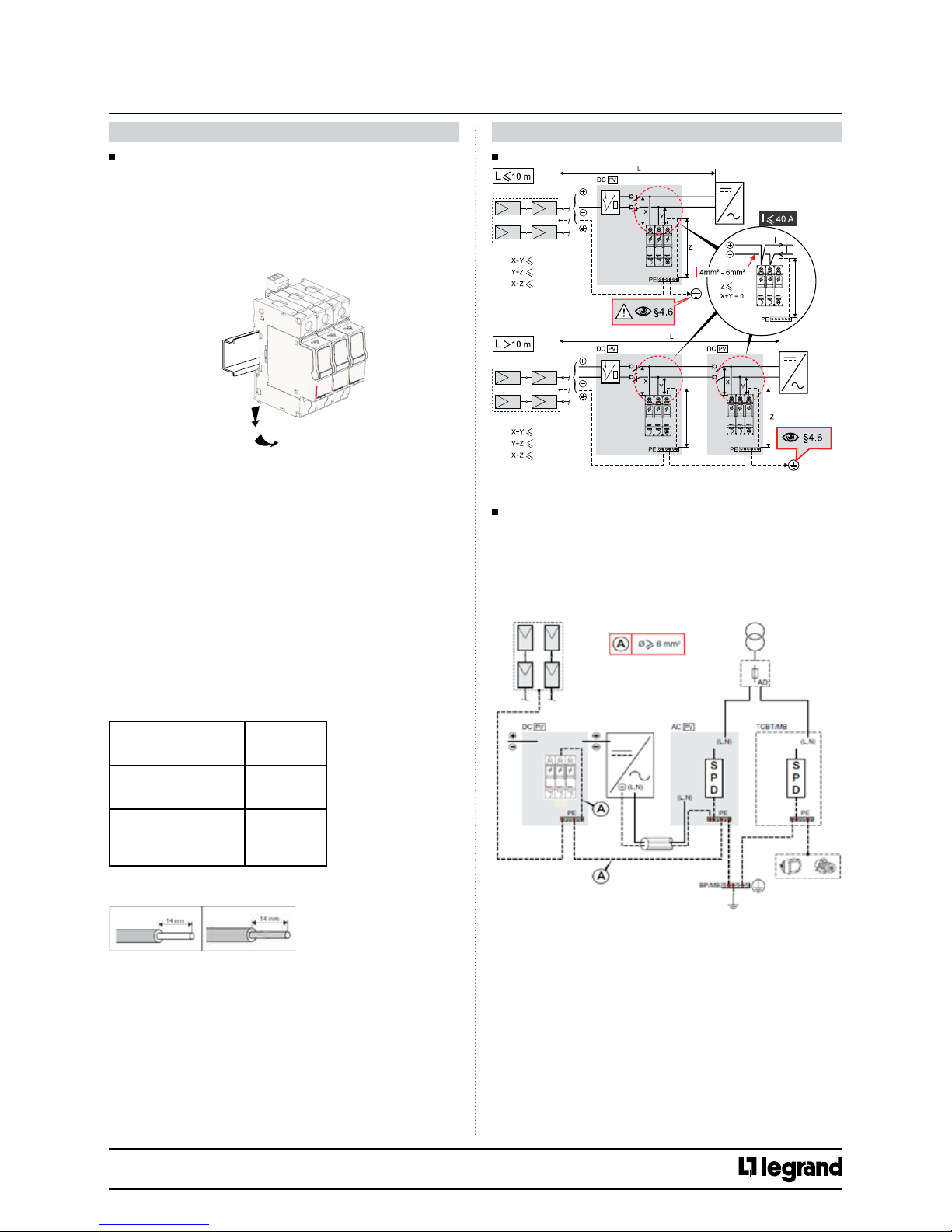
6.1 Protection of the DC part of the PV installation
To provide correct voltage surge protection of the DC part of the PV
installation, a PV SPD is recommended:
- On each inverter input (1) (in DC enclosures in accordance with guide
UTE C 15-712-1, SPD compulsory according to the type and location of
the installation to be protected, see UTE C 15-712-1)
- Close to the panels (in group junction boxes according to guide UTE C
15-712-1) when they are more than 10 m away from the inverter or the
DC enclosure (2)
(1) For multi-input or multi-MPPT inverters, it is advisable to use an SPD on
each input
(2) PV generators with a Uocmax voltage of less than 600 V:
According to guide UTE C 15-712-1, this protection is only necessary if
Legrand 600 V SPDs are installed close to the inverters. This protection is
nonetheless recommended for widespread PV installations with very long
lines.
6.2 Protection of the AC part of the PV installation
Likewise, for correct protection of the AC part of the PV installation,
it is advisable to group the inverters together in the same equipment
room as the main panel (main LV distribution board) connecting the PV
installation to the LV grid. Thus a single AC SPD (1) is all that is needed
to protect the main LV distribution board (SPD compulsory according
to the type and location of the installation to be protected, see UTE C
15-712-1).
If the inverters are not installed in the equipment room in which the
main LV distribution board is located (or are installed outdoors) an
AC SPD is also necessary close to each inverter.
Recommended types of AC SPD:
PV installation
power
Main LV board
protection
Installations
with lightning
conductors (3)
Main LV board
protection
Installations
without a lightning
conductor
Protection close
to inverters (2)
P < 36 kWc Type 1
(Iimp 12.5 kA)
SPD
protected
SPD
protected
P < 100 kWc Type 1
(Iimp 25 kA)
Type 2
(Imax 70 kA)
Type 2
(Imax 15 kA)
P > 100 kWc Type 1
(Iimp 25 kA)
Type 1
(Iimp 25 kA)
Type 2
(Imax 40 kA)
(1) An additional AC SPD is also necessary close to each inverter that is more
than 10 m away from the main LV distribution board. This SPD must be the
same type as those used close to the inverters (see above table).
(2) AC SPDs needed close to each inverter that is
- more than 10 m away from the main LV distribution board
- installed outdoors or outside the equipment room in which the main LV
distribution board is installed
(3) When a PV installation is protected by lightning conductors, it is
advisable to create an isolated lightning protection system (isolated LPS)
as described in standard NF EN 62305, maintaining adequate separation
distances between the metal structures of the panels and the LPS (lightning
conductors and downcomers).
6. LEGRAND RECOMMENDATIONS (continued)
6.3 Protection of the AC part of the existing installation
(consumption part)
To ensure correct voltage surge protection of the whole installation
(PV installation and installation on the consumption side), it is advisable
to protect the AC installation on the consumption side so as to avoid
any possible risk resulting from voltage surges on the PV installation or
voltage surges from the grid.
Since both electrical installations usually have a common earthing
system, SPDs are recommended on both installations to avoid any
possible problem of equipotentiality or feedback from earth.
The SPDs must be the same type as the AC SPDs recommended for
AC protection of the PV installation (see section 6.2). SPDs for the
secondary enclosures must be the same type as those recommended
for protection close to the inverters (table above in section 6.2).
See also the technical data sheets for T1 and T2 SPDs for 230/400 V~
systems.
6.4 Guide UTE C 15-712-1
According to this guide, the use of PV SPDs for protection on the DC
side is compulsory:
- if lightning conductors are present
- depending on the lightning risk analysis* (according to the distance
between panels and inverter and the local lightning strike density)
(see article 13)
The use of AC SPDs is compulsory on the AC side:
- if lightning conductors are present
- if the local lightning strike density is greater than 2.5 (see NF C 15-100
article 443)
Note: The use of SPDs is usually also compulsory if a lightning risk
analysis has been carried out according to standard NF EN 62305
(IEC 62305). In this case, refer to section 6.2 and the previous table,
considering an installation equipped with lightning conductors and
incorporating all the necessary protection close to the equipment.
*Given the expense of panels and inverters, we strongly recommend that
SPDs are always installed.
7. CONFORMITY
Complies with standard NF EN 50539-11 and drafts PR NF EN 61643-31
and future standard IEC 61643-31.
Used to comply with the installation requirements and
recommendations in guides UTE C 15-712-1, TS 50539-12 and also
standards IEC 60364-7-712 and IEC 61643-32.
Conforms to Directive: 2014/35/EU
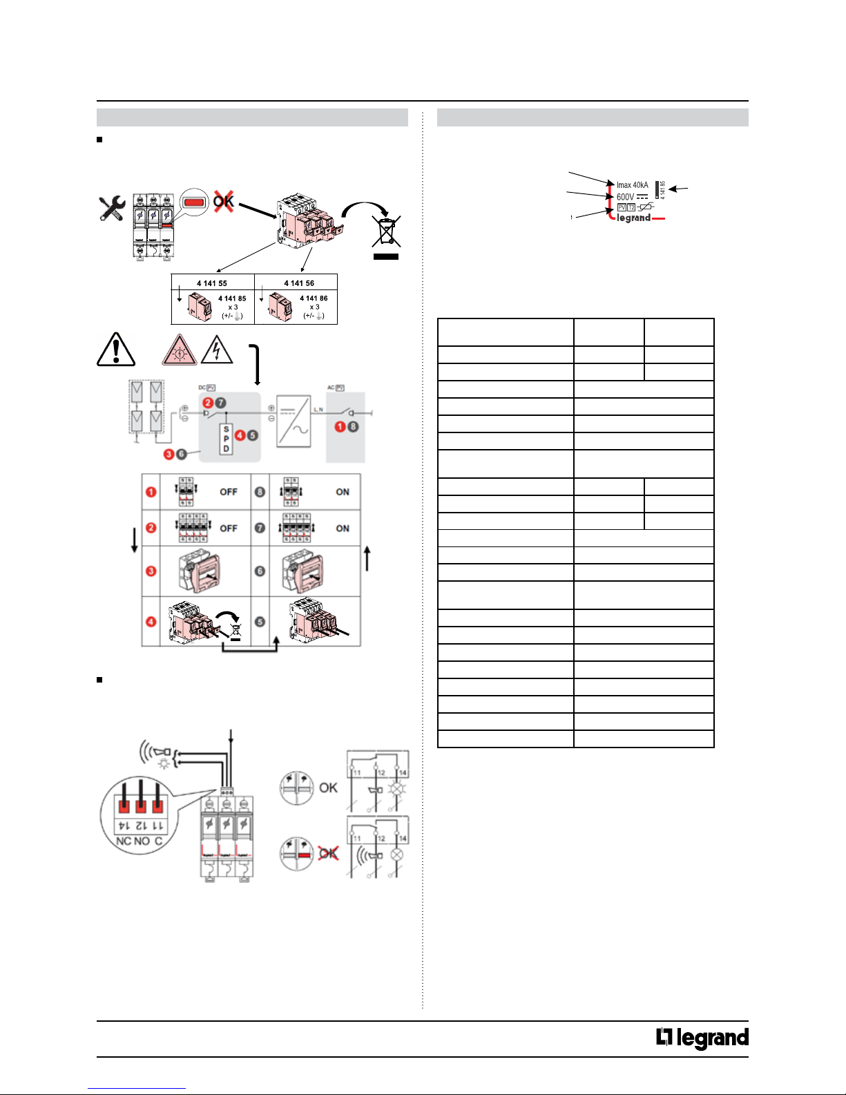
8. ACCESSORY
Replacement plug-in modules:
Plug-in module
Cat. No. Voltage Associated base
4 141 85 600 VDC 4 141 55
4 141 86 1000 VDC 4 141 56
With LED indicator:
- Green: SPD operational
- Red: plug-in module needs to be replaced
Replacing plug-in modules: see section 4.7

This manual suits for next models

3

Other LEGRAND Surge Protector manuals

LEGRAND LEXIC 030 00 User manual

LEGRAND

LEGRAND LEXIC 030 00 User manual

LEGRAND SANUS SA-OWSP60 User manual

LEGRAND

LEGRAND SANUS SA-OWSP60 User manual

LEGRAND Wiremold Perma Power M6BZ-15 User manual

LEGRAND

LEGRAND Wiremold Perma Power M6BZ-15 User manual

LEGRAND 0 503 98 User manual

LEGRAND

LEGRAND 0 503 98 User manual

LEGRAND 4 141 50 User manual

LEGRAND

LEGRAND 4 141 50 User manual

LEGRAND Celiane 671 93 Instruction Manual

LEGRAND

LEGRAND Celiane 671 93 Instruction Manual

LEGRAND 0 505 10 User manual

LEGRAND

LEGRAND 0 505 10 User manual

LEGRAND RJ 45 Cat 5e User manual

LEGRAND

LEGRAND RJ 45 Cat 5e User manual

LEGRAND SANUS SA-OWSP42 User manual

LEGRAND

LEGRAND SANUS SA-OWSP42 User manual

Popular Surge Protector manuals by other brands

ELAC ProteK PB-62S Setup guide

ELAC

ELAC ProteK PB-62S Setup guide

Exsys EX-47290 quick start guide

Exsys

Exsys EX-47290 quick start guide

OEZ SVC-350-3-MZ Instructions for use

OEZ

OEZ SVC-350-3-MZ Instructions for use

Bretford CFPS Specifications

Bretford

Bretford CFPS Specifications

Emos P54252 manual

Emos

Emos P54252 manual

Mersen Surge-Trap STZ series installation instructions

Mersen

Mersen Surge-Trap STZ series installation instructions

SC&T SP001VP user manual

SC&T

SC&T SP001VP user manual

Hamlet Zelig Stop user guide

Hamlet

Hamlet Zelig Stop user guide

APCO Aviation P5B-FR quick start guide

APCO Aviation

APCO Aviation P5B-FR quick start guide

Rocket Fish RF-HTS130 Guide d'installation rapide

Rocket Fish

Rocket Fish RF-HTS130 Guide d'installation rapide

Rocket Fish RF-HTS3117 Quick setup guide

Rocket Fish

Rocket Fish RF-HTS3117 Quick setup guide

Tripp Lite TLM626 Specifications

Tripp Lite

Tripp Lite TLM626 Specifications

Rocket Fish RF-HTS100 Guía De Instalación Rápida

Rocket Fish

Rocket Fish RF-HTS100 Guía De Instalación Rápida

Rocket Fish RF-HTS100 Guide d'installation rapide

Rocket Fish

Rocket Fish RF-HTS100 Guide d'installation rapide

Tripp Lite HT706TV owner's manual

Tripp Lite

Tripp Lite HT706TV owner's manual

watt box WB-600-FP owner's manual

watt box

watt box WB-600-FP owner's manual

Tripp Lite LC 1200 owner's manual

Tripp Lite

Tripp Lite LC 1200 owner's manual

Tripp Lite TLP1008TEL manual

Tripp Lite

Tripp Lite TLP1008TEL manual

manuals.online logo
manuals.online logoBrands
  • About & Mission
  • Contact us
  • Privacy Policy
  • Terms and Conditions

Copyright 2025 Manuals.Online. All Rights Reserved.