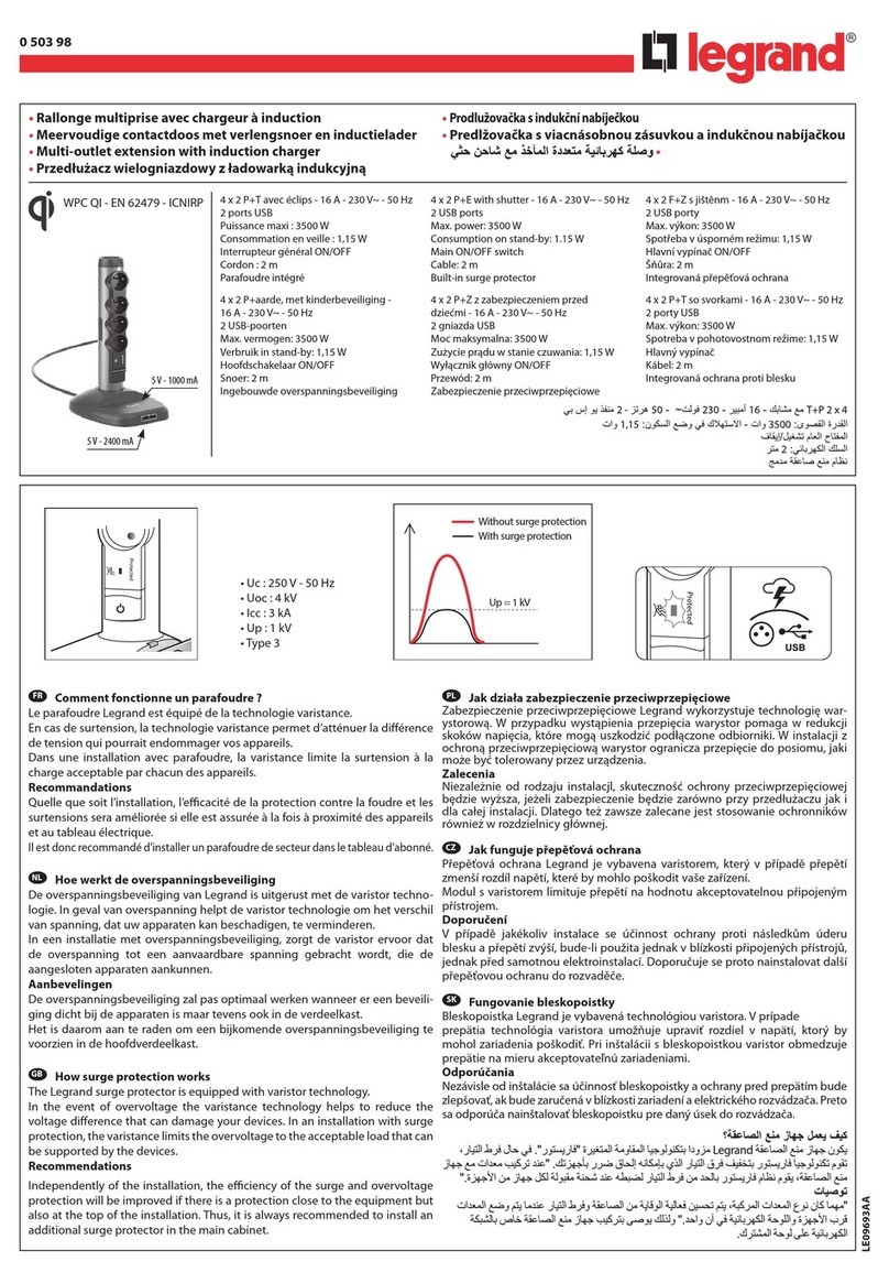
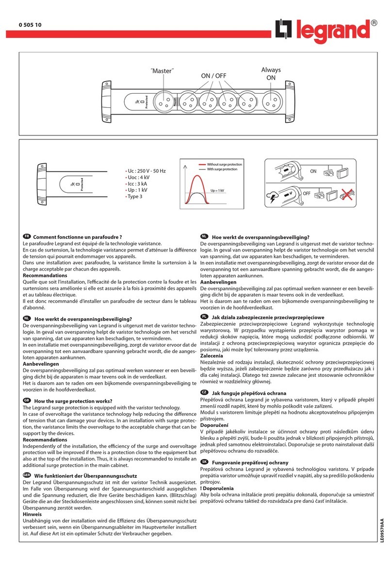
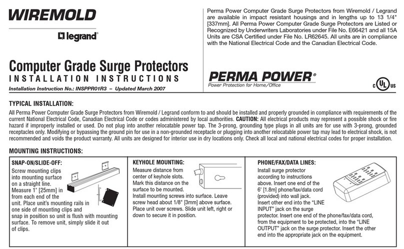
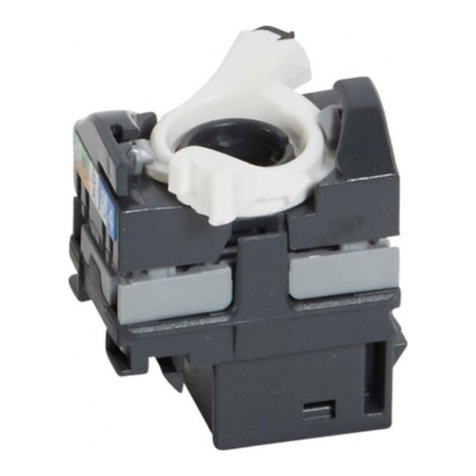
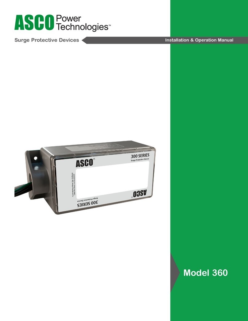
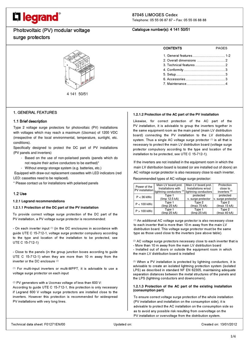
LEGRAND Celiane 671 93 Instruction Manual

622
Celiane™
gniazda wtyczkowe podwójne, wyjścia kablowe
Pak. Nr ref.
Gniazdo wtyczkowe podwójne 16 A – 250 V~
10 0671 37 Gniazdo 2 x 2P+Z
Do montażu w puszce pojedynczej przy użyciu
pazurków lub wkrętów.
Zaciski śrubowe. Dostarczane z uchwytem
montażowym i pazurkami. Do wyposażenia
w plakietki nr ref. 0686 47 (biała), 0687 57 (piaskowa),
0689 37 (grafitowa), 0689 47 (tytanowa).
Gniazda wtyczkowe wielokrotne 16 A – 250 V~
Z zaciskami automatycznymi sprężynowymi
iprzesłonami styków.
10 0671 24 Podwójne 2 x 2P+Z
Do montażu w uchwycie nr ref. 0802 52
z ramką podwójną.
10 0671 26 Potrójne 3 x 2P+Z
Do montażu w uchwycie
nr ref. 080253 z ramką potrójną.
10 0671 28 Poczwórne 4 x 2P+Z
Do montażu w uchwycie
nrref.0802 53 ze specjalną
ramką 6/8-modułową.
Wyjścia kablowe
Dostarczane z uchwytem kabla
10 0671 81 Wyjście kablowe
10 0671 83 Wyjście kablowe z 4 zaciskami
sprężynowymi przelotowymi (1,5 mm2)
do łatwego podłączenia urządzeń.
0671 37 Tytan 0671 24 Nikiel aksamitny
Celiane™
zabezpieczenia, ograniczniki przepięć, zaślepki
Pak. Nr ref. Ochronnik przeciwprzepięciowy
Zabezpieczenie instalowane w pobliżu komputerów
lub urządzeń elektronicznych w instalacji chronionej
już przez ogranicznik przepięć w rozdzielnicy głównej.
Może ograniczać przepięcie w obwodach gniazd
pojedynczych lub zespolonych – maksymalnie 5
gniazd pojedynczych lub 10 gniazd podwójnych.
Zapewnia ciągłość zasilania w przypadku wystąpienia
przepięcia (atmosferycznego lub sieciowego).
Zgodny z normą EN 61 643-11.
Znamionowy prąd wyładowczy (In): 1,5 kA.
Maksymalny prąd wyładowczy (Imax): 6 kA.
Poziom ochrony: (Up): L-N: 1 kV.
Napięcie w obwodzie otwartym (Uoc): 3 kV.
Uc L-N: 250 V~.
Ochrona sygnalizowana przez diodę LED:
– zielona: ochronnik przepięciowy sprawny;
– czerwona: należy wymienić wkładkę ochronnika.
10671 93 16 A – 250 V~
10676 93 Wkładka ochronnika
Zaślepki
10
10
10
0681 43
0684 43
0679 43
Biały
Tytanowy
Grafitowy
0671 93 Szkło czarne0671 28 Aluminium
Nowe produkty oznaczone są czerwonym numerem referencyjnym

CelianeTM
671 93 - 676 93
671 93 676 93
N
NL
L
SPD
aParafoudre modulaire
Surge Protective Device
•Modulaire bliksemafleider
•Surge protective device
•Modularer Blitzschutz
•Pararrayos modular
PE
30 mA
• Raccordement •Aansluiting •Connection •Anschluss •Conexión
• Principe d’installation •Installatieprincipe •Installation method •Installationsschema•Principio de instalación
Respecter strictement les conditions d’installation et utilisation.
Avant toute intervention, couper le courant.
Neem de installatie - en gebruiksvoorwaarden nauwgezet in acht.
Onderbreek voor eni
g
e in
g
reep de stroom.
You must comply with the installation and use conditions.
Cut off the current before carr
y
in
g
out an
y
work.
Einbau- und Betriebsbedingungen genau befolgen.
Vor Arbeiten am Gerät Stromversor
g
un
g
unterbrechen.
Respetar estrictamente las condiciones de instalación y de utilización
.
Antes de cualquier intervención, cortar la corriente.
N0064JM1/01
230 VA
(TT, TNS)
Uc (L/N - L/PE) 255 VA
Icc max. 4,5 kA
IL16 A
•Non livré
•Nitch mitgeliefert
•Not supplied
•No entregado
•Niet gelerved

• Fonctionnement
•Werking
•Operation
•Betriebsanzeige
•Funcionamiento
• Voyant vert
Protection opérationnelle
• Groen lampje
Operationele bescherming
• Green indicator lamp
Operational protection
• Grüne LED
Blitzschutz aktiv
• Piloto verde
Protección operacional
• Recommandation •Aanbeveling •Recommendation •Empfehlung •Recomendación
• Vérifier régulièrement que la LED verte est allumée.
Cassette de remplacement : 0676 93
- Débrocher la cassette du parafoudre avant de vérifier la résistance dÕisolement
de l’installation.
• Controleer regelmatig of de groene LED brandt.
Reservecassette : 0676 93
- Maak de cassette van de bliksemafleider los alvorens de isolatieweerstandvan
de installatie te controleren.
• Regularlycheck that the green LED is on.
Replacement cassette : 0676 93
- Pull the cassette out from the SPD before checking the isolation resistance of
the installation.
• Regelmäßig nachprüfen obdie grüne LED leuchtet.
Austauschkassette: Best.-Nr. 0676 93-
- Die Kassette des Blitzschutzes vor dem Überprüfen der Installation auf
Isolationswiderstandabklemmen.
• Comprobar regularmente que el LED verde esté encendido.
Cassette de reemplazo : 0676 93
- Desenchufar el cassette del pararrayos antes de comprobar la resistencia de
aislamiento de la instalación.
• Voyant rouge
La protection a été effectuée
Prise sous tension mais non protégée
Changer la cassette
• Rood lampje
De bescherming is effectief
Stopcontact onder spanning
Vervang de cassette
• Red indicator lamp
The protection has been performed
Socket poweredup
Change the cassette
• Rote LED
Blitzschutz wurde ausgelöst
Steckdose unter Spannung
Kassette auswechseln
• Piloto rojo
La protección se ha efectuado
Toma en tensión
Cambiar el cassette
Veiligheidsvoorschriften
Dit product moet bij voorkeur door een vakbekwame elektricien geïnstalleerdworden. Bij een
onjuiste installatie en een onjuist gebruik bestaat het risico van elektrische schokken of brand.
Lees alvorens de installatie uit te voeren de handleiding door en houd rekening met de specifieke
montageplaats van het product.
Het apparaat niet openen. Alle Legrandmogen uitsluitendgeopenden gerepareerdworden door
personeel dat door Legrandis opgeleiden bevoegdverklaard. In geval van ongeoorloofdope-
nen of repareren kan geen enkele aansprakelijkheidaanvaardworden, vervalt het recht op ver-
vanging en zijn de garanties niet meer geldig. Gebruik uitsluitendoriginele accessoires
.
Sicherheitshinweise
Dieses Produkt darf nur durch eine Elektro-Fachkraft eingebaut werden. Bei falschem Einbau
bzw. Umgang besteht Risiko von elektrischem Schlag oder Brand.
Vor der Installation die Bedienungsanleitung lesen, den produktspezifischen Montageort
beachten.Das Gerät nicht öffnen. Alle Produkte von Legranddürfen ausschließlich von durch
Legrandgeschultes undanerkanntes Personal geöffnet undrepariert werden. Durch
unbefugte Öffnung oder Reparatur erlöschen alle Haftungs-, Ersatz- und
Gewährleistungsansprüche. Nur Originalzubehör benutzen.
Consignes de sécurité
Ce produit doit être installé de préférence par un électricien qualifié. Une installation et une utilisa-
tion incorrectes peuvent entraîner des risques de choc électrique oud’incendie.
Avant d’effectuer l’installation, lire la notice, tenir compte du lieude montage spécifique auproduit.
Ne pas ouvrir l’appareil. Tous les produits Legranddoivent exclusivement être ouverts et réparés
par du personnel formé et habilité par LEGRAND. Toute ouverture ouréparation non autorisée
annule l’intégralité des responsabilités, droits à remplacement et garanties.
Utiliser exclusivement les accessoires d’origine.
Safety instructions
This product shouldbe installedpreferablyby a qualifiedelectrician. Incorrect installation anduse
can entail risk of electric shock or fire.
Before carrying out the installation, readthe instructions andtake account of the product's specific
mounting location.
Do not open up the device. All Legrandproducts must be exclusivelyopenedandrepairedby per-
sonnel trainedandapprovedby LEGRAND. Anyunauthorisedopening or repair completelycancels
all liabilities andthe rights to replacement andguarantees.
Onlyuse genuine accessories.
Medidas de seguridad
Este producto debe ser instalado preferentemente por un instaladore electricista cualificado. La ins-
talación yutilización incorrectas pueden generar riesgos de descargas eléctricaso de incendio.
Antes de efectuar la instalación, leer el manualy, tener en cuenta el lugar de montaje específico del
producto.
No abrir el aparato. Todos los productos Legranddeben ser abiertos yreparados exclusivamente
por personal formado yautorizado por Legrand.Cualquier apertura o reparación no autorizada
anula la integridadde las responsabilidades, derechos decambio ygarantías.
Utilizar exclusivamente accesorios originales.
FR LU
GB I E
ES
DE
NL BE

87045 LIMOGES Cedex
Telephone: 33 0 5 55 06 87 87 - Fax: 33 0 5 55 06 88 88
Cat. No(s).: 671 93 - 676 93
CélianeTM
Voltage surge protector
Technical data sheet: F00536EN/00 Updated: Created: 03/03/2010
1/2
1. GENERAL CHARACTERISTICS
Protection between phase nad neutral of socket outlets connected
downstream against overloads generated by the electrical network
upstream of the surge protective device by creating a discharge current
on the network and/or earthing link.
To be used in combination with a voltage surge protector installed in
the panel.
2. RANGE
3. FITTING
Unclip the draw-out module to access the terminal screws:
4. OVERALL DIMENSIONS
5. CONNECTION
Terminal type: screw connection
Capacity: 2 x 2.5 mm2
Type of screwdriver: flat-blade 4 mm
Designation Cat. No. Nbr.
of gang Connection Weight
(g)
Surge voltage
protector 671 93 1 With screws 91
Spare module 676 93 1 With screws 60
45
45
32.5 11.6
SPD
Surge Protective Device
PE
30 mA
N
NL
L

CélianeTM
Voltage surge protector
Cat. No(s).: 671 93 - 676 93
Technical data sheet: F00536EN/00 Updated: Created: 03/03/2010
2/2
6. OPERATION
6.1 Surge protection function
• Surge protective devices are designed to limit transient overcoltages
of atmospheric and industrial origin.
• Thez have a certain capacity to absorb energy and age with each
operation; it is therefore normal for them to be out-ot-service after a
certain number of operations. The imminent out-of-service status is
signalled and the draw-out module should be replaced.
• Surge protective devices are designed to be installed at use points and
are to be used in combinaison with the installation’s original modular
protection.
• Thez are not designed to provide sole protection for an installation
in a building likely to be hit by direct lightning strikes (e. g. buildings
equipped with lightning arresters). This would immediately put the
device out-of-service by exceeding its maximum discharge capacity.
•
Overloads of atmospheric origin occur between the active conductors
and the earth. Thez are highly charged and uncontrolled.
• Overloads of industrial origin occur between the active conductors
(P+N) and are not so highly charged.
• Céliane surge protective devices are equipped with an operation indi-
cator light (to be checked on a regular basis):
- Mains supply present and green indicator light on: operational protec-
tion.
- Mains supply present and red indicator light on: change the module.
- Once the draw-out module is out-ot-service the installation is no longer
protected but remains powered (including the withdrawn module).
7. TECHNICAL DATA
7.1 Mechanical characteristics
IP 20 (without rocker)
7.2 Material characteristics
Base: Polycarbonate (RAL 7016)
Cover plate: Polycarbonate (RAL 9003)
7.3 Electrical characteristics
Self extinguishing: 650° C / 30 s
Max. steady state voltage: 250 VAC
Mains rated voltage: 230 VAC (+ 6 % - 10 %)
Frequency: 50/60 Hz
Current: 16 A
Type of fuse: 5 x 20 rapid type 6.3 A
Response time: L-N: 25 ns
Protection level: according to NF EN 61-643-11 L-N: 1 kV: 1.5 kA
Leakage current at 250 VAC: < 1 mA
Rated discharge current: 1.5 kA
Maximum current: 6 kA
For joined sockets L < 1
8. CLEANING
Without cleaning.
To standard
NF EN 61-643-11
}
This manual suits for next models
1
Table of contents
Other LEGRAND Surge Protector manuals

LEGRAND
LEGRAND SANUS SA-OWSP42 User manual

LEGRAND
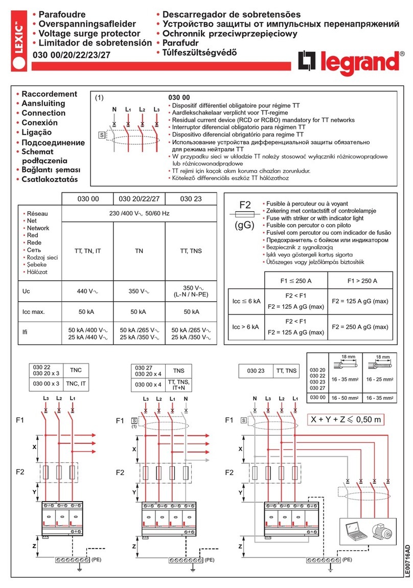
LEGRAND LEXIC 030 00 User manual

LEGRAND
LEGRAND 0 503 98 User manual

LEGRAND
LEGRAND 4 141 50 User manual

LEGRAND
LEGRAND 0 505 10 User manual

LEGRAND
LEGRAND RJ 45 Cat 5e User manual

LEGRAND
LEGRAND SANUS SA-OWSP60 User manual

LEGRAND
LEGRAND Wiremold Perma Power M6BZ-15 User manual

LEGRAND
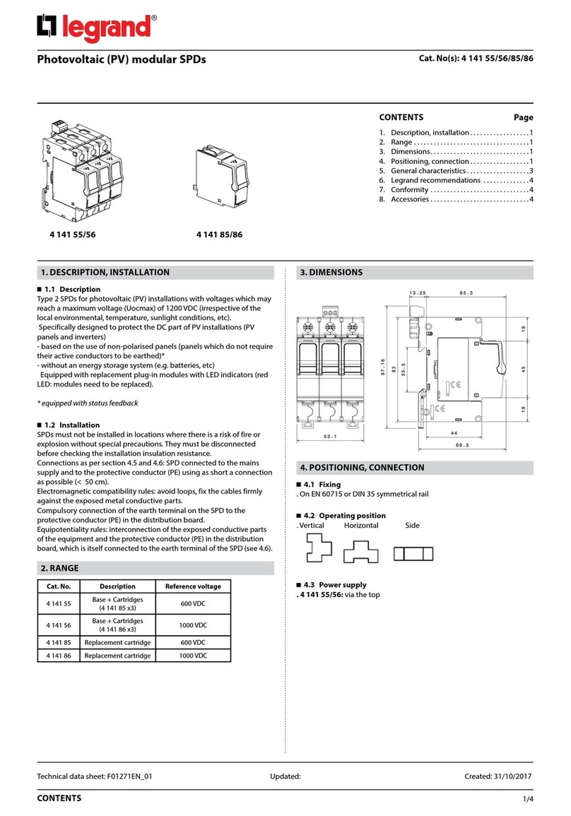
LEGRAND 4 141 55 Instruction Manual