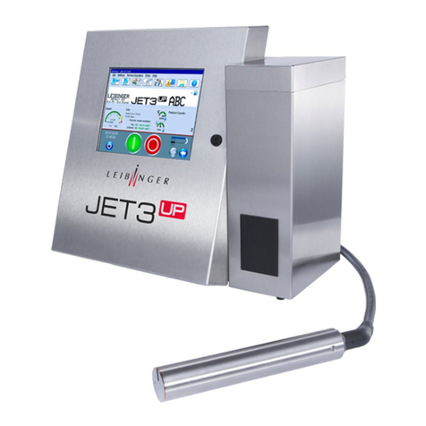
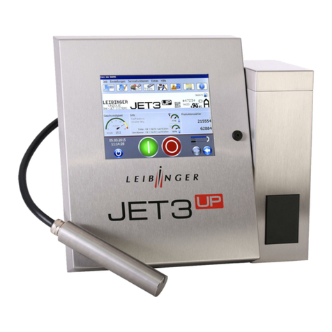
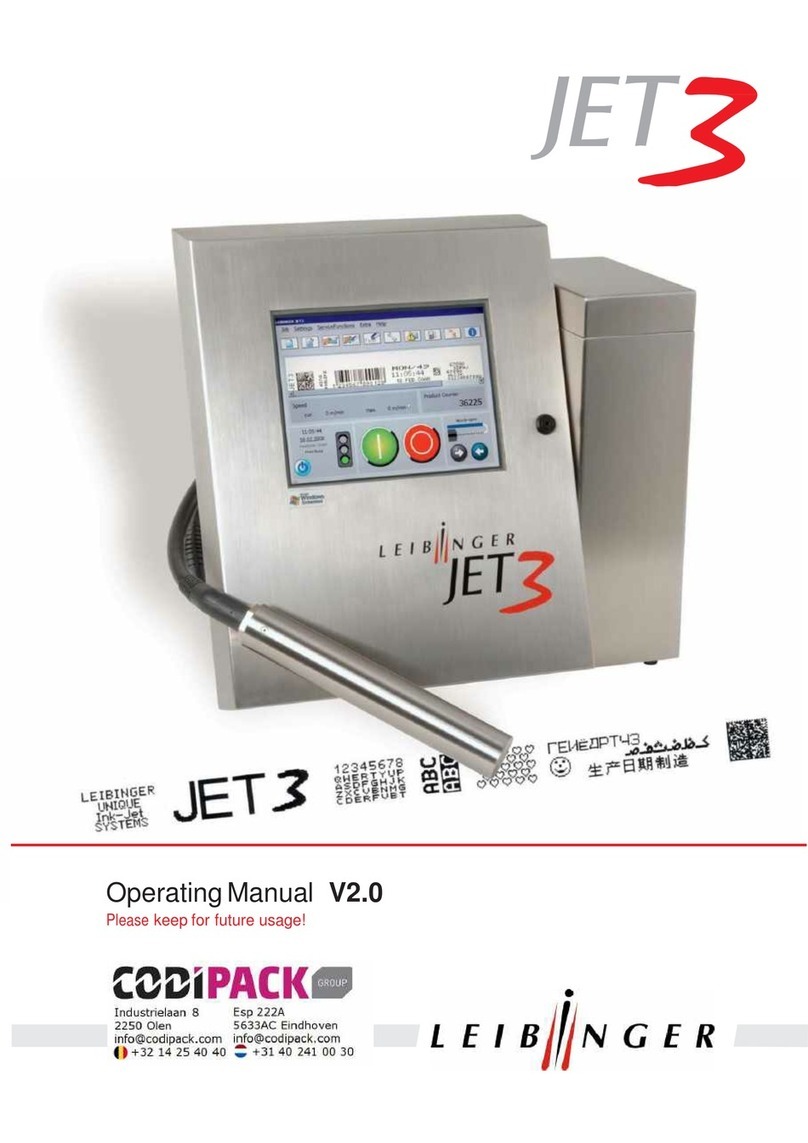
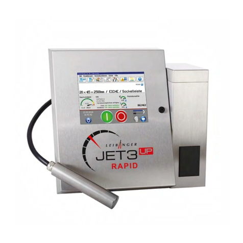
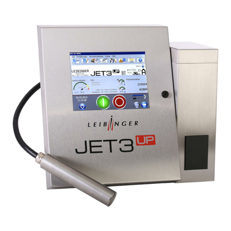
Leibinger JET Rapid User manual

JET Rapid
JET Rapid Wire
JET Rapid Wire PI
Operating Manual V1.02
Please
keep for future reference!


Seite 1
Release R.1.02 JET3up RAPID

Page 2
High Speed Line Release R.1.02
Table of content
1General overview ......................................................................... 3
1.1 Publisher ....................................................................................................................... 3
1.2 Introduction.................................................................................................................... 5
1.3 Document information ................................................................................................... 7
1.4 Warranty........................................................................................................................ 7
2Safety ......................................................................... 8
2.1 Scope of risks................................................................................................................ 8
2.2 Operating staff............................................................................................................... 9
2.3 Dangers due to electrical energy................................................................................... 9
2.4 Conformity ................................................................................................................... 10
3Technical Data of the High Speed Line ....................................................................... 11
3.1 Connection values and ambient conditions:................................................................ 11
3.2 Cabinet: ....................................................................................................................... 11
3.3 Print head ventilation / JET RAPID Wire (PI) and Speed Plus .................................... 12
3.4 Technical data of the High Speed Line ....................................................................... 14
3.5 Overview about the printheads.................................................................................... 17
4Available inks (All types of the High Speed series)........................................................... 21
4.1 Ink selection of the High Speed Line........................................................................... 21
4.2 Cleaning requirements ................................................................................................ 22
4.3 Hydraulic settings ........................................................................................................ 23
5Operation and Software ....................................................................... 24
5.1 Print- and printstyle parameters .................................................................................. 24
5.2 Print modes of the High Speed Line............................................................................ 24
6Adjustment of the printhead ....................................................................... 27
6.1 Printhead positioning and printout quality ................................................................... 28
6.2 Examples of printouts.................................................................................................. 33
7Errormessages and failures (complete High Speed Line)................................................. 35
8Cleaning and maintenance (complete High Speed Line).................................................. 36
9Apendix ....................................................................... 41
9.1 Technical illustrations .................................................................................................. 41
Page 3
Release R.1.02 High Speed Line
1 General overview
1.1 Publisher
For questions regarding the operation and running of the Leibinger High Speed Line
printers as well as in service case please contact the listed dealer address.
Dealer address
Paul Leibinger GmbH & Co. KG
Marking&Coding Systems
Daimlerstraße 14
D-78532 Tuttlingen
Federal Republic of Germany
Phone +49 74 61/92 86-0
Fax +49 74 61/92 86-1 99
Service hotline phone +49 74 61/92 86-8 63
Service hotline fax 0 74 61/92 86-8 69
American Branch Office
Paul Leibinger
Numbering Machine LTD
2702-B Buell Drive
East Troy, WI 53120 USA
Tel. +01 262.642-4030
Fax. +01 262.642.4033

Page 4
High Speed Line Release R.1.02
We reserve all rights, in particular the right to translate, distribute and reproduce. No part of
this manual must be reproduced or distributed and stored through the use of electronic data
processing systems or made accessible to third parties in any form (redrawn, photocopied,
microfilmed or through any other process) without the written consent of the publisher.
We reserve the right to make alterations to the scope of delivery at any time in the form of
technology, hardware, software as well as the corresponding materials (and manual extracts)
as a result of innovative further development of our devices.
Texts, illustrations and technical drawings have been compiled with the greatest of care.
Nevertheless errors cannot be excluded. Consequently no warranty can be assumed for the
correctness of the content of this manual and no claims can be asserted against Paul
Leibinger GmbH & Co. KG.
We shall be grateful for information regarding possible printing errors as well as for
suggestions for the further optimization of the device manual.
Authoritative for the scope of delivery is not the manual but rather the written order
confirmation.
The using of this manual assumes the knowledge of the respective industrial standards and
methods!
© Copyright 2019 Paul Leibinger GmbH & Co.KG

Page 5
Release R.1.02 High Speed Line
1.2 Introduction
We are pleased that you have decided in favour of a LEIBINGER device of the High Speed
Line and welcome you as one of our customers.
Now you own an inkjet printer that has been developed and constructed on the basis of
many years of experience and using the latest Leibinger technology. This results in a high
degree of quality and the renowned Leibinger reliability.
The new high-speed printer series is designed for all print jobs for which the current
version of the JET3up is not fast enough.
IMPORTANT
The following manual is a supplement of the JET3up manual.
It contains the specific informations of the High Speed Line series with its
4variants:
-JET Rapid
-JET Rapid Option Speed Plus
-JET Rapid Wire
-JET Rapid Wire (PI)
Please note:
It is absolutely necessary before starting to read accurate not only
this supplement manual but the main manual. Only the main manual
contains all necessary descriptions to get sure that either by an
failure electrical connection or a failure using an injury of the device
and / or an exposure of the operator or third persons happens.
Important Information
There are several significant differences between the JET3up and the
printers of the High Speed Line series.
The differences affect parts of the printer as well as service procedures.
It is highly recommended thoroughly checking the
manuals and the accessories catalogue for the
differences between the JET3up and the
High Speed Line series.
The following list gives an overview about the parts that are different for
the High Speed Line series in comparison to the JET3up:
Controller board
Parts of the printhead (please see details in accessories catalog)
High pressure ink valve (VV)
Regarding service and adjustment procedures the main differences are:
Hydraulic settings
Ink jet adjustments

Page 6
High Speed Line Release R.1.02
INFORMATION
Please pay particular attention to the safety instructions of the groups
Safety instructions and accident prevention when handling
consumables (ink and solvent).
Our devices are subjected to a quality control in our plant prior to delivery. If despite this
the device or parts of it should be damaged or their function disturbed please advise us of
this as fast as possible.
It is only through the use of inks and solvents from Paul Leibinger GmbH & Co. KG that
optimum operating characteristics can be achieved.
Should other inks and solvents be used all warranty claims will expire.
PRODUCT LIABILITY
No alterations whatsoever must be carried out on the entire Rapid device. No
liability will be accepted for damage or dangers resulting from inadmissible
alterations.
WARNING
Danger of explosion!
The device should be only operated outside of explosive areas!
The installation has to be carried out according to the installation
instructions of the manufacturer!

Page 7
Release R.1.02 High Speed Line
1.3 Document information
The instruction Release R.1.02 of 05.11.2019 is valid for the High Speed Line printer
with the given below serial number.
Stick in serial number
1.4 Warranty
The warranty conditions for the High Speed Line can be seen from the order confirmation.
The warranty presupposes that the device or the installation is operated correctly in
accordance with the available warranty conditions and any possible additional manuals
and descriptions prepared by us.
At this point we wish to make explicit reference to the fact that it is only when using solvent
and ink from Paul Leibinger GmbH & Co. KG that the optimum operating characteristics
can be achieved.
In the event of use of other inks and solvents all warranty entitlements shall cease
to apply.

Page 8
High Speed Line Release R.1.02
2 Safety
2.1 Scope of risks
The high performance industrial printer of the High Speed Line series has been built in
accordance with state-of-the-art standards and recognized safety requirements and has
been equipped with protective devices.
The InkJet-printer works with flammable liquids which are ink and solvent.
At incorrect usage or misuse may result in danger of health of the operator or further
people, as well as property damages.
All persons, which are entrusted with the initial operation, commissioning, operating,
service and maintenance must be specifically trained and qualified about the handling with
ink and solvent.
Before the first usage of the printer in particular the operating manual as well as the safety
data sheets of the ink and solvent have to be read and noted.
Operational and safety checks of the installation were carried out before it left the factory.
In case of improper handling or misuse, however, there are dangers for:
the health of the operating staff
the high performance printer and other real assets of the plant operator
the efficient operation of the high performance printer
All persons entrusted with the putting into service, the operation, the maintenance and the
overhauling of the high performance printer must
have the necessary qualification and
strictly comply with this operating manual.
YOUR safety matters!

Page 9
Release R.1.02 High Speed Line
2.2 Operating staff
Only trained personnel must operate the device. The personnel must have the
corresponding mechanical and electrical training to operate the inkjet printer
professionally. The operator is responsible for third parties in the working area of the
inkjet printer.
The owner-operator must make this operating manual accessible to the printer operator
and has to ensure that the operator has read and understood it.
Personnel in training can work on or with the inkjet printer only when supervised by an
experienced operator.
2.3 Dangers due to electrical energy
ELECTRICAL WORK
The electrical and electronic components of the high performance printer
are under voltage. The device must only be opened by trained personnel
or by Leibinger service technicians.
Prior to the opening of the device, the device must be switched off and the
mains plug removed.

Page 10
High Speed Line Release R.1.02
2.4 Conformity

Page 11
Release R.1.02 High Speed Line
3 Technical Data of the High Speed Line
3.1 Connection values and ambient conditions:
Input voltage / frequency
100-240 V, 50-60 Hz
Power consumption
Ø20W
Temperature range
+5°C bis +45°C
Relative humidity
Max. 90% rel. humidity (not condensating)
3.2 Cabinet:
Material
Stainless steel
Dimensions (w/d/h)
486mm/286mm/446mm
Weight
20,5 KG
Protection class
IP 54

Page 12
High Speed Line Release R.1.02
3.3 Print head ventilation / JET RAPID Wire (PI) and Speed Plus
The JET Rapid Wire (PI) and Speed Plus printers are equipped with a print head ventilation.
The print head ventilation ensures longer cleaning intervals and reduces the risk of
condensation within the print head.
3.3.1 Basics about the functionality of the printhead ventilation
The print head of the JET Rapid Wire (PI) and Speed Plus printer has to be mounted at a
distance between nearly zero und 5 mm to the substrate. This close installation provides the
shortest trajectories for ink droplets. This is the basic requirement for a fast and precise print
out. However, it also bears the risk of contaminating the print head by bursting ink droplets.
With the head ventilation there is a constant air stream at the outlet of the print head that
works like a protective shield against the remains of ink droplets that burst on the surface of
the substrate.
Example: print head ventilation of the RAPID Wire (PI) with stepped head cover
The print head of the JET Rapid Wire (PI)
during the printing process. The ink jet is
illustrated as a series of red droplets.
With the JET Rapid Wire (PI) the distance
between the substrate, normally a cable,
and the print head is nearly zero.
The illustration shows an enlargement of
the print head. The red ink droplets burst
on the surface of the substrate, causing
smaller droplets that are bouncing back in
the direction of the outlet of the print head.
The compressed air of the head ventilation
is illustrated as blue droplets. With the
slight over pressure in the print head, the
compressed air prevents the intrusion of ink
droplets into the print head.

Page 13
Release R.1.02 High Speed Line
3.3.2 Technical description head ventilation
The JET Rapid Wire (PI) and the JET Rapid Speed Plus printers are equipped with a
connector for compressed air. The connector is located on the back panel of the hydraulic
cabinet.
Technical data
Parameter
Value
Maximum input pressure:
10 bar (145.035 psi)
Factory preset for the pressure control:
1,4 bar (20.305 psi)
Recommended flow:
-2l/min JET Rapid Wire (PI)
-2 l/min Speed Plus
Warning
Operation is only permissible with clean, dry, oil-free and filtered compressed
air (Size of filter 8 μm).
Using compressed air that does not meet these requirements may cause
serious damages to the print head.
Attention
Make sure that there is a permanent compressed air supply!
The printer does not monitor the permanent compressed air supply!
There will be no warning in case the permanent compressed air
supply fails!
Connector for
compressed air

Page 14
High Speed Line Release R.1.02
3.4 Technical data of the High Speed Line
3.4.1 JET Rapid / Option Speed Plus
JET Rapid
Option Speed Plus
Print head
SK6
SK6 HS
Print head
dimensions
Umbilical
Standard: 3m
Standard: 3m
Maximum
printing speed
Up to 30% faster than the JET3up
800 m/min
Characters per
inch [cpi]
10 cpi at 413 m/min
Print mode:
7x5 dots
8 cpi at 800 m/min
Print mode:
5x5 speed
Available inks
Please see chapter:
4.1 Ink selection of the High Speed Line
Please see chapter:
4.1 Ink selection of the High Speed Line
Oscillator
frequency
128 kHz
128 kHz
Nozzle size
55 µm
50 µm
Available print
modes
Same print modes as JET3up
Up to 32 dots
Line Mode
3x7 tower
3x7 tower small
5x5
5x5 small
5x5 speed
5x5 speed small
7x5
7x5 speed
Print lines
Multi line / up to 5 lines
Single line
Pressured air
required
No. Optional available.
Yes. 2 l/min
Applications
JET3up applications that require higher
production speeds especially if there is a 2-
or 3-line print out required. E.g. filling
systems or bottling plants.
Single-line high speed printing with a
maximum print height of 2,5 mm.
E.g. serial numbers, expiry dates, lot
numbers
212 mm
43
mm
217 mm
43
mm

Page 15
Release R.1.02 High Speed Line
3.4.2 JET Rapid Wire
Wire print head with stepped head cover
Wire print head with beveled head cover
Print head
Wire
Wire
Print head
dimensions
Umbilical
Standard: 3m
Standard: 3m
Maximum
printing speed
1000 m/min
800 m/min
Characters per
inch [cpi]
6 cpi at 1000 m/min
Print mode:
5x5 dot speed
8 cpi at 800 m/min
Print mode:
5x5 speed
Ink- and
solvent
Please see chapter:
4.1 Ink selection of the High Speed Line
Please see chapter:
4.1 Ink selection of the High Speed Line
Oscillator
frequency
128 kHz
128 kHz
Nozzle size
50 µm
50 µm
Available print
modes
Line Mode
3x7 tower
3x7 tower small
5x5
5x5 small
5x5 speed
5x5 speed small
7x5
7x5 speed
Line Mode
3x7 tower
3x7 tower small
5x5
5x5 small
5x5 speed
5x5 speed small
7x5
7x5 speed
Print lines
Single line
Single line
Pressured air
required
Yes. 2 l/min
Yes. 2 l/min
Applications
Cable/wire/tubes with diameters up to 5 mm
Cable/wire/tubes with diameters larger
than 5 mm
High speed printing with a maximum
print height of 2,5 mm.
43
mm
217 mm
43
mm
217 mm

Page 16
High Speed Line Release R.1.02
3.4.3 JET Rapid Wire PI
Wire printhead with stepped head cover
Wire printhead with beveled head cover
Print head
Wire
Wire
Print head
dimensions
Umbilical
Standard: 3m
Standard: 3m
Maximum
printing speed
700 m/min
600 m/min
Characters per
inch [cpi]
7 cpi at 700 m/min
Print mode:
5x5 dot speed
8 cpi at 600 m/min
Print mode:
5x5 dot speed
Ink and solvent
Please see chapter:
4.1 Ink selection of the High Speed Line
Please see chapter:
4.1 Ink selection of the High Speed Line
Oscillator
frequency
96 kHz
96 kHz
Nozzle size
60 µm
60 µm
Available print
modes
Line Mode
3x7 tower
3x7 tower small
5x5
5x5 small
5x5 speed
5x5 speed small
7x5
7x5 speed
Line Mode
3x7 tower
3x7 tower small
5x5
5x5 small
5x5 speed
5x5 speed small
7x5
7x5 speed
Print lines
Single line
Single line
Pressured air
required
Yes. 2 l/min
Yes. 2 l/min
Applications
Printing with pigmented inks on
cables/wires/tubes with diameters up to 5
mm. Eg.: white ink on black cable
Printing with pigmented ink on
cables/wires/tubes with diameters larger
than 5 mm
High speed printing with a maximum
print height of 2,4 mm.
43
mm
217 mm
43
mm
217 mm

Page 17
Release R.1.02 High Speed Line
3.5 Overview about the printheads
3.5.1 JET Rapid
Head cover: Standard (SK6)
From the dimensions, the print head is equivalent to the SK6 print head of the JET3up.
The JET Rapid works with the same print modes as the JET3up. Due to the higher operating speeds,
the recommended distance between print head and substrate is 15 mm.
-Shorter distances bear the risk of contaminating the print head
-Larger distances may have a negative effect on the quality of the printouts.
217mm
Ø 43mm
Recommended:15 mm

Page 18
High Speed Line Release R.1.02
3.5.2 JET Rapid Option Speed Plus
The JET Rapid with the Option SPEED PLUS comes with the same print head technology as
the JET Rapid Wire but he is only available with the beveled head cover which provides single
line printouts up to a speed of 800 m/min
It was designed for high-speed applications and substrates that are not suitable for the
JET Rapid Wire with its stepped head cover.
Printhead mechanic
Head cover Option SPEED PLUS:
Angled surface
The slightly angled surface allows an optimized mounting of the print head.
217mm
Ø 43mm
Other manuals for JET Rapid
1
This manual suits for next models
3
Table of contents
Other Leibinger Printer manuals

Leibinger
Leibinger JET2 neo User manual

Leibinger
Leibinger RAPID Series Manual

Leibinger
Leibinger JET3 User manual

Leibinger
Leibinger JET2 neo User manual

Leibinger
Leibinger JET3 User manual

Leibinger
Leibinger JET3 User manual

Leibinger
Leibinger Jet 2 User manual

Leibinger
Leibinger JET3 up User manual

Leibinger
Leibinger JET3 up User manual