Leica Geosystems MC 200 Depthmaster User manual

MC 200 Depthmaster
User Manual
Version 1.1
English

IMC200
Introduction
Introduction
Purchase Congratulations on the purchase of a MC 200 Depthmaster.
This manual contains important safety directions as well as instructions for setting
up the product and operating it. Refer to "5 Safety Directions" for further information.
Read carefully through the User Manual before you switch on the product.
To ensure safety when using the system, please also observe the directions and
instructions contained in the User Manual and Safety Handbook issued by the:
• Machine manufacturer,
• Controller manufacturer and
• Sensor manufacturer.
Product
identification The type and the serial number of your product are indicated on the type plate.
Enter the model and serial number in your manual and always refer to this informa-
tion when you need to contact your agency or Leica Geosystems authorized service
workshop.
Type: _______________
Serial No.: _______________

Introduction MC200 II
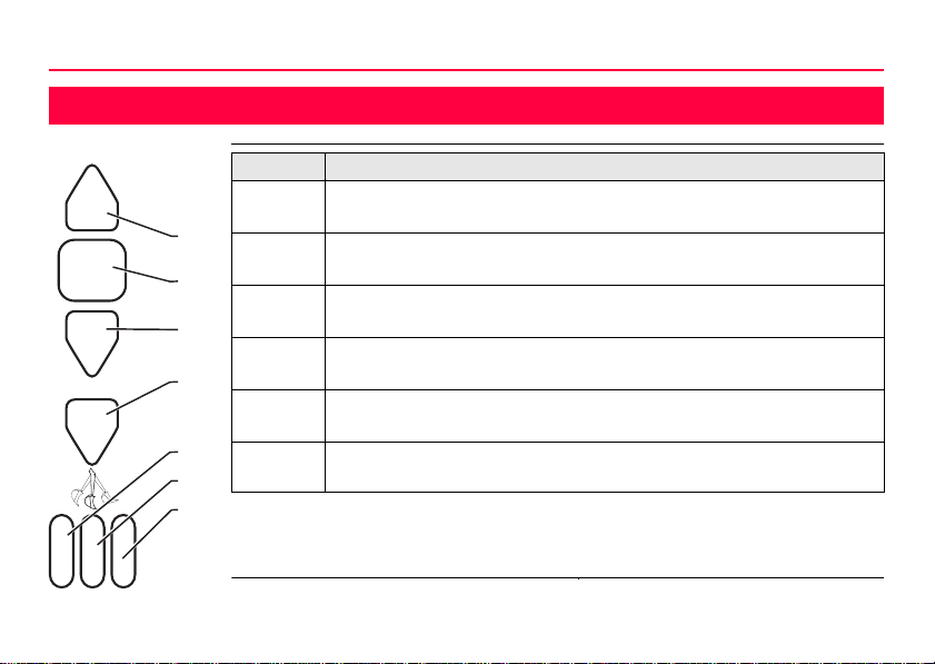
Symbols The symbols used in this manual have the following meanings:
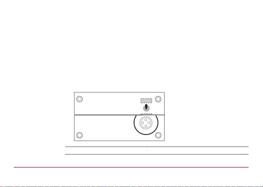
It is recommended to set-up the unit while reading through this manual.
Index The index is at the back of the manual.
Type Description
Danger Indicates an imminently hazardous situation which, if not
avoided, will result in death or serious injury.
Warning Indicates a potentially hazardous situation or an unintended
use which, if not avoided, could result in death or serious
injury.
Caution Indicates a potentially hazardous situation or an unintended
use which, if not avoided, may result in minor or moderate
injuryand/orappreciablematerial,financialandenvironmental
damage.
Important paragraphs which must be adhered to in practice as
they enable the product to be used in a technically correct and
efficient manner.

Description of the System MC200 1-1
1 Description of the System
Warning This product may be installed on building machinery only by an appropriately trained
and qualified specialist.
Warning Unauthorized modification of machines by mounting the product may alter the func-
tion and safety of the machine.
Precautions:
Follow the instructions of the machine manufacturer. If no appropriate instruction is
available, ask machine manufacturer for instructions before mounting the product.

1-2MC200
Description of the System
Features and main
components
*) Reception Area (Top View)
a) Power Button
Press the button on the side you will be viewing to activate the indicators for that
side, or press both at start-up to activate both sides.The Power Button only func-
tion when the battery pack powers the laser sensor. Otherwise, a control panel
switch or connecting to an external battery activates the laser sensor.
a
b
c
d
e
f
200° *)

Description of the System MC200 1-3
b) Hidden Switch
See "3.4 Optional Functions" on page 3-8.
c) Grade Position Indicators
Blink rapidly to indicate the position of the machine’s cutting edge relative to
grade (See below.)
d) Plumb Indicators
Blink rapidly to show the vertical position of the machine’s arm. (See below.)
e) Low Battery Indicators
Become lit when the battery pack has less than 6 hours of operating charge.
f) Cable Connector
Provides a connection to a control panel or to a 12 or 24 Volt DC battery. Use
sensorbatterycable toconnecttoabattery:theblackwire to negative; the white
wire to positive.
Shake-to-Wake:
After 5 minutes of no movement, the laser sensor goes into “stand-by” to
conserve power. Move the laser sensor to activate it (after 90 minutes of no
movement, it shuts completely off).

1-4MC200
Description of the System
g) Mounting Clamps
Allow you to easily attach the laser sensor to square and round mounting poles
without having to lift the laser sensor over the top of the pole. The laser sensor
includes shock isolators to absorb and dampen vibrations from the machine.
Magnetic Mount:
Allows the sensor to be attached to the arm of the machine.
Remove by pulling sharply from a lower corner of the magnet.
g
h
i

Description of the System MC200 1-5
h) Battery Pack
The rechargeable batteries provide power to the laser sensor for over 48 hours
on a single charge.
Recharge the battery pack by connecting a 778855 Charger, 100-240 VAC to
the charger connector.
Plug the DC power cable into the battery pack before plugging it into the mains
socket.
i) Narrow/Wide Switch
Remove the battery pack before activating the wide/narrow switch. The wide
channel is for wide band operation and the narrow channel is for narrow band
operation.

2-1MC200
Buttons
2Buttons
*) Memory Feature
When the laser sensor goes from within the rotating laser signal to above or
below it, the last indicator to detect the laser light blinks slowly.
1
2
3
4
5
6
7
Button Machine Control Operation
1Off-Grade,
Low*)-0.5 to -3.0 in. (-12 to -75 mm)
1+2 Near On-Grade,
Low -0.16 to -0.5 in. (-4 to -12 mm)
2On-Grade
±0.16 in. (±4 mm)
2+3 Near On-Grade,
High +0.16 to +0.5 in. (+4 to +12 mm)
3Off-Grade,
High*) +0.5 to +5.3 in. (+12 to +135 mm)
4, 5, 6, 7 There is no indication in Machine Control Mode. Connect a control
panel to enable Machine Control Mode.

Buttons MC200 2-2
*) Memory Feature
When the laser sensor goes from within the rotating laser signal to above or
below it, the last indicator to detect the laser light blinks slowly.
1
2
3
4
5
6
7
Button Excavator/Backhoe Operation
1Below Grade*)
-0.5 to -3.0 in. (-12 to -75 mm)
1+2 Below Grade (Narrow only)
-0.16 to -0.5 in. (-4 to -12 mm)
2On-Grade
Wide: ±0.5 in. (±12 mm)
Nar: ±0.16 in. (±4 mm)
2+3 Above Grade (Narrow only)
+0.16 to +0.5 in. (+4 to +12 mm)
3Above Grade
+0.5 to +1.7 in. (+12 to +43 mm)
4Above Grade*)
+1.7 to +5.3 in. (+43 to +135 mm)

Operation MC200 3-2
3.1 Battery
First-time use/charging
• The battery must be charged prior to using it for the first time because it is deliv-
ered with an energy content as low as possible.
• For new batteries or batteries that have been stored for a long time (> three
months), it is effectual to make 3-5 charge/discharge cycles.
• The permissible temperature range for charging is between 0°C to +35°C/+32°F
to +95°F. For optimal charging we recommend charging the batteries at a low
ambient temperature of +10°C to +20°C/+50°F to +68°F if possible.
• It is normal for the battery to become warm during charging. Using the chargers
recommended by Leica Geosystems, it is not possible to charge the battery if
the temperature is too high.
Operation/Discharging
• The batteries can be operated from -20°C to +55°C/-4°F to +131°F.
• Low operating temperatures reduce the capacity that can be drawn; very high
operating temperatures reduce the service life of the battery.

3-3MC200
Operation
3.2 Excavator/Backhoe Operation
a) Rotating Laser
b) Arm
c) Laser Sensor
d) Plane of Laser Light
abcd

Operation MC200 3-4
Procedure 1. Set up and level the Rotating Laser in a convenient location.
Make sure there will be a clear path between the rotating laser and laser sensor
at all times and that the laser signal will be within the 200° range of the laser
sensor.
2. Activate the laser sensor.
• Ifin“stand-by,”movethearmtoshake the lasersensorandstartit.Otherwise,
press the Power Button for the side(s) you will be viewing.
• If connected to the machine’s battery, it is on.
• If connected to a Control Panel, put the Control Panel’s Power Switch to
ON.
3. Begin digging and stop when the excavation is at the required depth.
Position the bucket and set it down at the finished elevation.
The bucket can be in any position, but it must be in the same position each time
you make a grade check.
4. Plumb the laser sensor.
Adjust the machine’s arm so the center Plumb Indicator is blinking.
5. Loosen the laser sensor’s Mounting Clamps and slide it up or down until
the “On-Grade” Grade Position Indicator is blinking.
When using the Laser sensor with magnetic mounts, place the laser sensor in
the bracket and set it at the correct height on the arm of the machine before

3-5MC200
Operation
attachingit.When using mounting clamps, tightenthe lasersensoratthecorrect
height.
6. Continue digging until a grade check is normally required and take a grade
check.
• Move the bucket to the same position as it was in Step 3 and lower it almost
to the cut.
• Plumb the laser sensor by moving the machine’s arm in or out until a center
Plumb Indicator is blinking.
• Set the bucket on the cut and read the elevation next to the blinking Grade
Position Indicator.

Operation MC200 3-6
3.3 Machine Control Operation
a) Rotating Laser
b) Hub Stake
c) Blue Top
d) Laser Sensor
e) Plane of Laser Light
abcde

3-7MC200
Operation
Procedure 1. Set up and level the Rotating Laser in a convenient location.
Make sure there is a clear path between the Rotating Laser and the MC 200
Depthmaster laser sensor.
2. Move the machine to the area to be graded and set the blade to a position
that is at finished grade, such as a Hub Stake or a “Blue Top.”
3. Set the Control Panel’s Auto/Manual Switch to "MANUAL" and set the
Power Switch to "ON".
4. Loosen the laser sensor’s Mounting Clamps and slide it up or down until
the “On-Grade” Grade Position Indicator is blinking
(It may be necessary to raise or lower the Rotating Laser). Tighten the Mounting
Clamps.
5. Operate the machine:
• Manual Mode. Begin moving the machine forward while observing the Grade
Position Indicators on the laser sensor or Control Panel.
Use the machine’s controls to keep the “On-Grade” Grade Position Indicator
blinking.

Operation MC200 3-8
3.4 Optional Functions
Switching to
Machine Control
Mode
The MC 200 Depthmaster can be made to operate as an excavator sensor or as a
machine control sensor. To switch between these modes - turn on the sensor, then
press the marked switch left of the Leica Logo.
In machine control mode, only the top three lights will function and the sensor will be
in narrow band.
Disabling Sleep
Mode The MC 200 Depthmaster will go into a “sleep mode” if no movement is seen in the
plumb indicator lights after five minutes. In certain applications (ie: dozers,
trenchers) it is desirable to disable this function.

3-9MC200
Operation
To disable the
sleep mode - Turn
off the sensor.
Press and hold the marked switch left of the Leica Logo, then turn on the sensor.
The sensor will go through it’s normal power-up sequence, then the two outer plumb
lights will flash to indicate the sleep mode has been disabled. Now let go of the
"hidden switch" and sleep-mode is disabled, the laser sensor is set to permanent
operations. The sleep mode must be disabled each time the sensor is turned on.
Table of contents