Leica SF 60 User manual

LEICA SF 60
INSTRUCTION MANUAL

EN
2
1
1a
1b
1c
2
3
4
5
6
7
89
10
8a
6a
6b
11
11a
11b
11c
11e
11d
1
12
13
14

EN
3
PART DESIGNATIONS
1Reflector head, with
adiffuser
bbounce card
cwide-angle diffuser
2Video light
3Sensor for cordless off-camera operation (behind infrared-per-
meable panel)
4AF assist light
5Input jack for connecting external battery pack (behind cover)
6Mounting foot with
aunlock button
blocking pin
7Power switch
8Mode dial and
aindex
9Ready LED / test flash button
10 LCD panel
11 Combination dial / rocker switch with settings for
achannel selection
baudible signal
cdevice pairing
dzoom mode / focal length
ebutton lock
12 Battery compartment cover
13 Clip-on softbox
14 Off-camera stand with ¼“ thread

EN
4
FOREWORD
Dear Customer,
Thank you for purchasing the Leica SF60 system flash unit, and
congratulations on choosing the best system flash solution for your
Leica camera. We wish you every enjoyment and success with your
new flash unit.
To get the most out of your Leica SF 60, please read this manual
before use.
Note:
You will find the manufacturing date of your Leica SF 60 on the
labels provided in the Warranty Card and/or on the packaging. The
date format is L Y M DD XXXXXXX:
L= Leica
Y= Year (1-0 (=2011-2020))
M= Month (1-9 = Jan.-Sep., A = Oct., B = Nov., C = Dec.)
DD = Day (0-31)
XXXXXXX = Firmware version
SIGNIFICANCE OF THE ADVISORY CATEGORIES
Note:
Additional information
Important:
Failure to observe this information can result in damage to the
camera, accessories, or the photos
Attention:
Failure to observe this information can result in personal injury

EN
5
TABLE OF CONTENTS
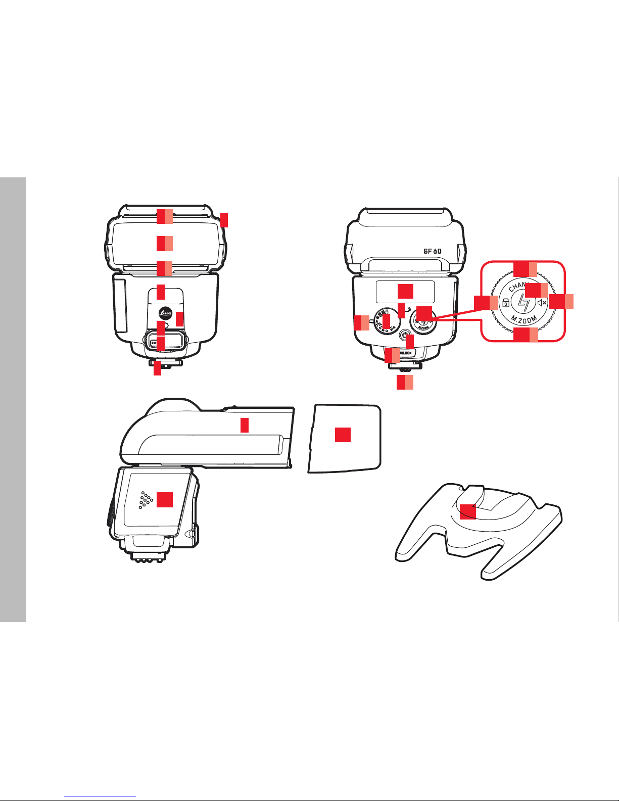
Designation of parts.....................................................................3
Foreword .....................................................................................4
Safety precautions .......................................................................6
Disposal of electrical and electronic equipment............................7
Compatible cameras ....................................................................8
Functions dependent on the camera model ..................................9
Preparation
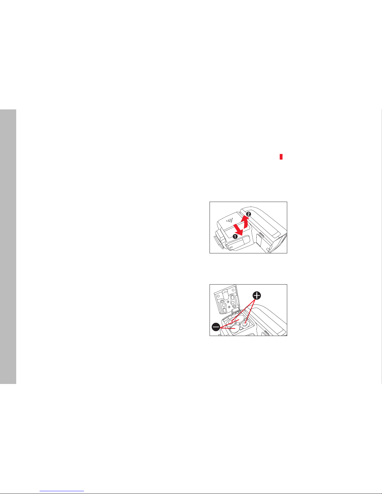
Power supply .............................................................................10
Changing the power source........................................................10
Battery disposal .........................................................................11
Mounting/unmounting the flash unit ..........................................12
Operation
Switching on and off ..................................................................13
Displays when the flash unit is switched on ................................13
Auto power off ...........................................................................13
Zoom reflector ...........................................................................14
Manual adjustment ....................................................................12
Wide-angle diffuser ....................................................................15
Flash modes ..............................................................................16
Fully automatic – A....................................................................16
Fully automatic – TTL..............................................................16
Setting flash exposure compensation ....................................17
Video light ..........................................................................18
Setting the light intensity ......................................................18
Manual flash mode – M...........................................................18
Partial light output settings ...................................................18
Cordless off-camera flash ........................................................19
Remote firing - SD/SF ..........................................................20
Remote control - ABC ......................................................20
Flash groups ......................................................................21
Channel selection...............................................................21
Audible signal.....................................................................22
Other settings/functions
Bounce flash..............................................................................23
Bounce flash with bounce card...................................................23
Clip-on softbox ..........................................................................24
Button lock ................................................................................24
Aspect ratio ...............................................................................24
Synchronization .........................................................................24
AF assist light ............................................................................25
External battery pack as power supply........................................25
Appendix
Maintenance and care................................................................26
Conditioning the capacitor of the flash unit.................................26
Troubleshooting .........................................................................26
Spare parts................................................................................27
Technical data............................................................................28
Leica service addresses .............................................................29
Guide number table...................................................................???

EN
6
SAFETY PRECAUTIONS
Attention:
Intended use
• This flash unit is designed and certified for lighting subjects for
photography purposes only. This device must not be used for
any other purpose.
• It must only be used with the accessories described in this
manual, or with accessories otherwise approved for use with it
by Leica Camera AG.
• The flash unit must never be fired in proximity to flammable
gases or liquids (benzene, solvents, etc.). Failure to observe this
can result in an EXPLOSION or FIRE!
• Avoid flash photography too close to the subject's eyes. The
extreme light output can cause retinal damage in humans and
animals, resulting in permanently impaired vision or even
blindness.
• Never use flash photography in the direction of oncoming traffic
of any kind, as drivers can be momentarily distracted, which can
cause accidents. Before taking shots of moving traffic, switch
the flash off or otherwise make sure that the flash will not be
triggered.
• Do not touch the diffuser after repeated flash firing, as it can
become very hot. Failure to observe this can result in burns!
• Never touch the contacts in the mounting foot of the flash unit.
• If the case of the device has been damaged and internal
components are visible, take care not to touch them – HIGH
VOLTAGE HAZARD!
• This also applies if there is a risk that water or other liquids
could have penetrated the device case, or any kind of metallic or
flammable object.
• In these cases, remove the batteries. Take great care when
doing so.
• Even after battery removal, the high-voltage circuitry can still
hold a sufficient charge to cause electric shock, burns or other
injuries.
• The device must therefore continue to be kept safe from
moisture (e.g. rain or splash water) and must not be handled
with moist hands. Do not attempt to disassemble, repair, or
modify the device! The device interior does not hold any
components that could be repaired by a layman.
• Please only use the batteries specified and approved in this
manual.
• Do not short-circuit batteries or expose them to excessive heat
(e.g. direct sunshine or fire).
• Depleted batteries must never be thrown into a fire!
• Do not attempt to recharge single-use dry cell batteries (primary
cells).

EN
7
Important:
• Protect your flash unit against excessive heat and humidity. Do
not store the flash unit in the glove compartment of your vehicle.
• Rapid changes in ambient temperature can result in condensa-
tion. Allow the flash unit time to acclimatize before using!
• Make sure that no opaque objects are positioned directly in
front of the diffuser or directly on it when the flash is triggered.
The diffuser must be clean. Failure to observe this can result in
burn damage to the objects or the diffuser due to the extremely
high energy output of the flash.
• The flash unit must only be used together with a camera-inte-
grated flash if this can be fully opened out or extended.
• Do not use batteries that are damaged in any way!
• Depleted batteries can leak battery acid, which could damage
the contacts. Always remove batteries from the device when not
in use.
DISPOSAL OF ELECTRICAL AND
ELECTRONIC EQUIPMENT
(Applies within the EU and for other European
countries with active waste separation policies.)
This device contains electrical and/or electronic components and
must therefore not be disposed of with normal household waste!
Make sure you bring this device to an approved electronic waste
collection point for recycling. The service is free of charge.
If the device contains batteries, whether rechargeable or not, these
must be removed first and disposed of separately in line with the
applicable regulations. Please contact your local authority, waste
disposal service, or the retailer from whom you purchased the
device for more information on correct waste disposal.
Note:
Correct exposure values were assessed as part of EMC testing
for CE marking.
Do not touch the SCA contacts!
In exceptional circumstances, touching the SCA contacts can
result in damage to the device.

EN
8
COMPATIBLE CAMERAS
The LEICA SF60 was designed for Leica cameras with autonomous
flash exposure control by way of TTL (Through-The-Lens) metering,
such as the Leica digital cameras of the S, SL, M, CL, and Q series.
The Leica SF60 can also be used with any other Leica camera
model, but only in manual mode.
However, using the LeicaSF60 with camera models of other
manufacturers can only be recommended with reservations.
Similarly positioned contacts in the accessory shoes of other
camera makes can use different electrical values, resulting in
incompatible signals that can adversely affect either or both of the
devices. Leica Camera AG therefore accepts no liability for any
damage that might occur in these cases beyond that which might
occur to the flash unit itself without outside influence.
Notes:
• The descriptions in this manual are generally limited to the use
of the Leica SF60 in conjunction with Leica camera models
from the current product range.
• This manual only describes the functions and settings of the
Leica SF60 flash unit itself. With very few exceptions, this also
applies to displays and indicators.
For this reason, it is important that you read the information on
flash photography in the manual of the camera model you are
using, paying particular attention to the flash features supported
by your camera, the camera settings you might need to make,
and the camera's flash photography displays and indicators.

EN
9
FUNCTIONS DEPENDENT ON THE CAMERA MODEL
The flash functions listed below are available (depending on the
equipment of the camera model used).
– Flash ready indication in camera's viewfinder / LCD panel
– Automatic flash sync speed control
– TTL flash mode
– Automatic fill-in flash mode
– Manual flash exposure compensation
– Normal or end-of-exposure synchronization (camera setting)
– Automatic high speed synchronization, if supported by camera
model
– Automatic zoom reflector control
– Pre-flash function to reduce red eye effect (camera setting)
– Cordless off-camera flash operation (remote settings and firing
control)
– Constant video light
– Automatic power off functions
Note:
If the camera model used does not supply the required data, or if
the lens used does not have the required data contacts for the lens
mount, functional restrictions can be expected.

EN
10
PREPARATION
POWER SUPPLY
The flash unit can be operated with the following power sources:
– 4 alkaline batteries, 1.5V, IEC type LR6 (AA/mignon size)
This type of battery is maintenance-free and suitable for
moderate power requirements.
– 4 nickel-metal hydride (NiMH) rechargeable batteries, 1.2V, IEC
type HR6 (AA/mignon size)
This type of rechargeable battery has a significantly higher
capacity than a nickel-cadmium (NiCd) rechargeable battery and
is more environmentally friendly, as it contains no cadmium.
More information on the capacity of the individual battery types
can be found on page 28.
Attention/important:
• Only use the power sources listed above. Failure to observe this
could damage the flash unit. This particularly applies to certain
types of lithium battery (1.5V, IEC type FR6, AA/mignon size).
These can heat up excessively during use and can cause burns,
despite the automatic overheating protection of the device!
• Always remove the batteries if you don't intend to use the flash
unit for an extended period of time.
CHANGING THE POWER SOURCE
When the recycling time between flashes begins to take more than
30s, this indicates that the batteries are depleted and should be
replaced. (Recycling time = time after flash is fired at full output
level (e.g. M) until the Ready LED 9lights up green again).
Procedure
1. Switch the flash unit off (see also the next section)
2. Slide forward the battery compartment cover and release it.
It will automatically spring open.
3. Remove the spent batteries and insert the new ones as shown
in the illustration
Make sure you insert each battery in the correct orientation!

EN
11
Attention:
Incorrectly inserted batteries can destroy the flash unit! Improper
battery use poses an EXPLOSION HAZARD!
4. To close the battery compartment, press down on the rear of
the cover and slide it back into place.
Notes:
• Always replace all of the batteries at the same time.
• All four batteries should be of high quality and must be the same
type.
BATTERY DISPOSAL
Never dispose of depleted batteries in household waste! Do your
part for the environment and take your depleted batteries to a
collection point.
Only dispose of batteries once they are completely spent. A battery
counts as spent when the device it powers no longer functions
correctly after extended battery use.
Cover the battery poles with adhesive tape to prevent a short
circuit.
Germany: As a consumer, you are required by law to return used
batteries. You can return batteries free of charge wherever they are
sold. Additionally, your town or local authority offers free public
collection points.
The following abbreviations can be found on the label of batteries
containing hazardous materials:
Pb = battery contains lead
Cd / Cad = battery contains cadmium
Hg = battery contains mercury
Li = battery contains lithium

EN
12
MOUNTING/UNMOUNTING THE FLASH UNIT
The description that follows also applies to mounting the flash unit
on the off-camera stand, except that you do not need to switch off
the camera in this case.
Mounting
2
1
1. Make sure the camera and the flash unit are switched off
2. Push the mounting foot of the flash unit into the camera’s
accessory shoe
The locking pin (6b) must audibly click into place.
On cameras with an accessory shoe that lacks the necessary hole
for the locking pin, the spring-loaded pin fully retracts into the
mounting foot of the flash unit and will not damage the surface of
the accessory shoe.
Removal
2
1
1. Make sure the camera and the flash unit are switched off (see
next page)
2. Press the unlock button (6a) and slide the flash unit out of the
accessory shoe of the camera

EN
13
OPERATION
SWITCHING ON AND OFF
Switching on
Press the button 7
Displays when the flash unit is switched on
• The Ready LED 9initially lights up red, and turns green as soon
as the flash is ready (after a few seconds, provided the battery
has sufficient charge).
• The symbols for the set flash mode appear on the LCD panel 10.
• In cameras that support this feature, the flash ready symbol will
appear in the camera's viewfinder and/or LCD panel.
Note:
You can press the Ready LED for a test flash.
Switching off
Press the button
Auto power off
To save battery power, the illumination of the LCD panel will dim a
few seconds after the last user action. In flash modes A, TTL, and
M(see pages 16/16/18), the flash unit will switch itself to standby
mode to conserve battery power about 2 minutes after the last
flash firing or the last user action. This is indicated by the Ready
LED, which will flash green.
In flash modes SD/SF (see page 20) orABC (see page 20), this
does not happen until after about 5 minutes.
The flash unit will power down completely if it is not used for more
than 60minutes, i.e. if no button is pressed, no dial is moved, and
no flash is fired.
Waking up the flash unit from standby:
Tap the shutter release button of the camera or press the
combination dial 11 in any direction
Notes:
• To protect the electronics from overheating, the flash unit will
automatically switch to a kind of cooldown mode for several min-
utes when necessary, for example, after a long series of
high-output flashes in rapid succession (between 20 and 30).
This state is indicated by the Ready LED 9, which flashes at an
interval of 1.5s. The device cannot be woken up until it has
finished cooling down. This automatic overheating protection is
also triggered if the batteries get too hot.
• If you don't intend to use the flash unit for an extended period of
time, we recommend switching it off and removing the batteries.

EN
14
ZOOM REFLECTOR
The flash unit is equipped with a zoom reflector that can adjust the
flash coverage to the focal length of the lens in use, from 24 to
200mm. This is done fully automatically for flash mode A(no
manual option available), only manually for flash mode SD/SF (no
automatic option available), or as selected (automatic and manual
options available) for flash modes TTL and M. The automatic focal
length adjustment also works with zoom lenses, such as the Leica
Vario lenses.
Manual adjustment
1. Press the combination dial 11 at the M.zoom option at the
bottom for about 1s
• The current setting is shown on the LCD panel 10.
2. Turn the combination dial to the setting you require. You can
select the "automatic" setting A, or a specific focal length (9
options from 24mm to 200mm)
3. Again press the combination dial at the bottom for about 1s to
exit the function
Hint:
If you are using a zoom lens and know that you won't always be
needing the full range of the flash, it can be helpful to set the flash
unit manually to the shortest focal length of the lens. In this way,
regardless of the focal length you select on the lens, your complete
field of view will always be adequately illuminated without you
having to adjust the flash settings all the time.
Example:
You decide to work with a zoom lens with a focal length range of
24 to 90mm. In this case, set the position of the zoom reflector to
24mm.
Notes:
• The automatic focal length adjustment of the zoom reflector only
works with camera models that transfer focal length information
to the flash unit. If this is not the case, you will need to adjust
the focal length setting manually.
The manual of your camera model will tell you what information
it will transfer to a connected flash unit of this type.
• The zoom reflector is not automatically adjusted in the following
cases:
– The reflector head is turned to the left or right
– The wide-angle diffuser has been pulled out
– The clip-on softbox is attached
• The last manual focal length setting you made will remain stored
even after the flash unit has been switched off.
• All the focal length settings on the flash unit that are described
in this manual refer to 35mm film format (24 x 36mm), or "full
frame" image sensor format. When using cameras with smaller
or larger image sensor or film formats, you will need to
determine the correct focal length settings on the basis of the
relevant conversion factor, in order to be able to take full
advantage of the flash range.
Example:
The Leica TL has an APS-C image sensor format (smaller than a
full frame sensor) so it has a conversion factor of 1.5. This
means that the image effect of its Summilux-TL 35 f/1.4 ASPH
lens is equivalent to that of a 50mm lens on a camera with a full
frame sensor. With a camera using the Summilux-TL 35 f/1.4
ASPH lens, you will therefore need to select the 50mm setting
for the zoom reflector.
The conversion factor for your camera can be found in the
relevant manual.

EN
15
WIDE-ANGLE DIFFUSER
The integrated wide-angle diffuser (1c) enables you to use
wide-angle lenses with focal lengths as short as 16mm.
Use
1. Pull the wide-angle diffuser out of the reflector head as far as it
will go 1and release it.
• It will automatically spring up into position.
2. To remove the wide-angle diffuser, fold it downward until it is
horizontal and push it back in all the way.
Notes:
• When the wide-angle diffuser is in use, the zoom reflector is set
to the shortest focal length setting (24mm), but the LCD panel
will display 16mm, corresponding to the actual focal length for
which the flash is now optimized. The focal length of the lens
you actually use has no influence on this. When the wide-angle
diffuser is removed and properly pushed back into the reflector
head, the flash unit will return to the previous setting.
• Using the wide-angle diffuser and the clip-on softbox (13, see
pages 2/3, 23 and 24) simultaneously is not recommended.
Notes on the range
• When shooting in close proximity to the subject, long lens
models and/or lens hoods can obscure the flash, resulting in
shadows in the lower part of your picture.
• Flash photography can also result in overexposure if you are too
close to the subject. In such cases, using the integrated bounce
card (s. S. 23) for an indirect flash, or using the clip-on softbox
included in the delivery package can help.
• For information on the maximum flash ranges, please refer to
the guide number table (see appendix) to avoid underexposure.

EN
16
FLASH MODES
The following flash modes are available:
Video light (see page 18)
SF Remote firing without pre-flash (see page 17)
SD Remote firing with pre-flash (see page 17)
MManual flash mode (see page 18)
AFully automatic flash mode
TTL Fully automatic flash mode with optional flash
exposure compensation
ABC Remote control (see page 19 et seq.)
Selection
Turn the Mode dial 8until the flash mode you wish to use is aligned
with the index 8a.
• The appropriate symbols will be displayed on the LCD panel 10.
FULLY AUTOMATIC FLASH MODE - A
This flash mode is the easiest way to achieve excellent flash
photography results. Flash exposure metering is performed by your
camera for this purpose. It measures the light reflected by the
subject through the lens (TTL).
Depending on your camera model, the flash unit will help this
metering by producing an almost unnoticeable pre-flash just before
the actual exposure.
This flash mode supports all the exposure modes offered by your
camera model: automatic program (P), shutter speed priority
(S/T), aperture priority (A) and manual setting (M).
FULLY AUTOMATIC FLASH MODE - TTL
Like A, but allows you to compensate the flash exposure of your
subject by setting an exposure value (EV) between -2 and +2, in
increments of one third of an EV.
Reason:
Automatic flash exposure control systems are adjusted to an
average light reflection factor by the subject of 25%. In some
cases, this can lead to underexposure or overexposure of the
subject, for example,
– if the main subject is either very dark or very bright or strongly
reflective
– if the main subject (average brightness) is very small and/or in
front of a bright or strongly reflective background (e.g.
backlighting), or in front of a very dark background (e.g. night
time).
• The LCD panel will show a light balance scale with EV digits
underneath to indicate that flash exposure compensation is
possible.

EN
17
Setting flash exposure compensation
Turn the combination dial 11 until the EV you wish to set by way of
compensation appears in the LCD panel
Set the EV back to 0.0 if you want to return to normal operation
without flash exposure compensation
Hint:
– Dark subject before bright background:
positive exposure value (EV)
– Bright subject before dark background:
negative exposure value (EV)
Notes:
• The above description only applies if your camera does not
already have an exposure compensation feature itself. If it does,
you must use the exposure compensation feature of your
camera instead of the flash exposure compensation feature of
the flash unit. In this case, please refer to the instruction manual
of your camera.
• Flash exposure compensation by changing the lens aperture size
on the camera is not possible, since the automatic exposure
program of the camera will automatically cancel out the
intended effect by ensuring the flash unit produces a corre-
spondingly higher or lower flash output.
• The possible exposure values have the following effects:
Positive EV = reduces the flash range
Negative EV = increases the flash range
Please also refer to the guide number table in the appendix.

EN
18
VIDEO LIGHT -
More and more cameras nowadays have video recording functions.
For this reason, this flash unit offers a video light mode 2as well as
the various flash modes.
• The LCD panel will show a light output scale with a digit value
underneath to indicate that the light intensity can be adjusted (in
9 increments).
Setting the light intensity
Turn the combination dial 11 until the level of illumination is as
required
• The light output level is displayed in the LCD panel.
MANUAL FLASH MODE – M
In manual flash mode, the flash unit will always use the maximum
flash output level unless separately adjusted. The flash intensity
can be compensated for by changing the lens aperture on the
camera according to the guide number and/or by manually
choosing a suitable partial light output setting. The partial light
output settings range from maximum level to 1/256 (corresponding
to 8 f-stops).
• The LCD panel will show a light output scale with a digit value
underneath to indicate that the output level can be adjusted.
Partial light output settings
Turn the combination dial 11 until the output level you wish to set
appears in the LCD panel

EN
19
CORDLESS OFF-CAMERA FLASH
The Leica SF60 can be used off-camera as well as in the camera's
accessory shoe, without requiring a connecting cord. This also
allows it to be used in complex illumination setups with any number
of additional flash units.
Leica SF60 flash units can be set up for off-camera operation in
one of two ways:
– With remote firing, in flash modes SD or SF (only manual flash
settings possible).
– With full remote control using the Leica SFC1 optional
accessory in the camera's accessory shoe, in flash mode ABC
(either manual flash settings or fully automatic TTL flash
mode possible).
Notes:
• The Leica SF60 can also be used off-camera in a group with
other flash units. Whether or not a flash unit is compatible with
the Leica SF60 for this purpose and what settings are required
can be found in the relevant instruction manual of the flash unit
concerned.
• When using off-camera flash units, a number of test pictures will
often be necessary with different flash unit setups, including
individual flash unit settings and reflector head positions, in
order to arrive at a satisfactory lighting solution.
However, if the ambient light is very bright, it may prove to be
impossible to achieve the desired lighting effect.
• The maximum distance between an off-camera Leica SF60 and
the camera for remote firing or remote control depends on the
flash mode used:
– SD and SF: Depends on the light intensity of the main flash
unit and can only be found by trial and error
–ABC : maximum 100m
Setting up and positioning the Leica SF60 for off-camera
operation
1. Make sure the flash unit is safely set up where you want it,
using the off-camera stand included in the delivery package for
optimum stability. This can be mounted on a tripod if required.
2. Position the reflector head 1as required
Note:
These steps must be followed separately for each off-camera flash
unit, regardless of how many are used.
Important:
• Do not fix the Leica SF60 to metal mounts or stands with
metallic surfaces. These could cause a short-circuit and damage
the flash unit.
• If you use the off-camera stand included in the delivery package
and wish to tilt the reflector head of the Leica SF60 upwards,
turn it 180° before doing so. This will give the flash unit a better
balance on the off-camera stand and greater stability.

EN
20
Remote firing - SD/SF
In these two flash modes, the Leica SF60 can be fired by the flash
of a so-called "master" flash unit, i.e., another Leica SF60 that is
mounted on the camera or otherwise physically connected to it.
These two flash modes SD and SF differ from one another only in
the way they synchronize the off-camera Leica SF60 with the
master flash unit, which depends on whether the latter uses a
pre-flash (SD mode must be set) or not (SF mode must be set).
This ensures that the off-camera Leica SF60 is only fired in
synchronization with the main flash of the master flash unit.
As regards flash exposure control, both flash modes correspond to
the Mflash mode. For more information, see page 18.
Use
1. Select the required focal length setting of the zoom reflector
(not A, see page 14)
2. Then turn the mode dial 8until the flash mode SD is aligned
with the index 8a.
3. Fire a test flash on the master flash unit, to see whether it uses
pre-flash or not
4. If the off-camera Leica SF60 fails to fire in synchronization,
set the flash mode to SF instead.
Notes:
• All the off-camera Leica SF60 flash units must be set to the
same flash mode.
• The AF pre-flash function of the camera must be switched off.
Remote control - ABC
This flash mode requires a Leica SFC1 controller (optional
accessory) in the camera's accessory shoe, for controlling and
firing any number of off-camera Leica SF60 flash units over a
range of up to 100m1. You can either address all of the off-camera
flash units at the same time, with identical settings, or divide them
into up to three separate groups, with individual flash settings per
group.
The following settings are possible:
– Manual or automatic focal length adjustment of the zoom
reflector (see page 14), with different settings per group
– Flash exposure compensation in TTL mode or manual partial
light output settings in Mmode (see pages 17/18), with
different settings per group
– Manual flash exposure control in Mmode or automatic flash
exposure control in TTL mode (see pages 18/16), with
synchronized settings for all groups
Note:
The controller uses a number of RF frequencies or "channels" in
the 2.4GHz band. This means that several controllers can work
simultaneously, using different 2.4GHz channels, providing a fast
(lag-free) and safe (error-free) communication between the
devices.
1Range at optimum conditions. Electric cables, metal objects, walls, other
2.4GHz controllers in the vicinity and other sources of interference can shorten
the maximum possible range.
Other manuals for SF 60
2
Table of contents
Other Leica Camera Flash manuals