LEITZ Diamaster WhisperCut User manual

104/2012 ID.524571 V2.0
DeutschEnglish
日本語中文 ItalianoFrançaiseEspañolPortuguêsРусский
Betriebsanleitung - Diamaster WhisperCut
User manual - Diamaster WhisperCut
anuale d´uso - Diamaster WhisperCut
ode d’emploi - Diamaster WhisperCut
Instrucciones de servicio - Diamaster WhisperCut
Instruções de utilização - Diamaster WhisperCut
Руководство по эксплуатации - Diamaster WhisperCut
使用手册-金刚石静音修边铣刀取扱説明書−ダイヤマスターウィスパーカット

2 04/2012 ID.524571 V2.0
DeutschEnglish
日本語中文 ItalianoFrançaiseEspañolPortuguêsРусский
1 Allge einer Teil
Das Werkzeug entspricht den Anforderungen gemäß EN 847-1.
Vor Inbetriebnahme des Werkzeuges ist die Betriebsanleitung zu beachten!
1.1 Kennzeichnung
1. Hersteller
2. Ident-Nr.
3. aximale Abmessung (Dmax x SBmax x BO)
4. aximale Betriebsdrehzahl (n max)
5. Vorschubart
6. Werkzeugbezeichnung
7. Schneidstoff
8. Weitere Kennzeichnung des Herstellers
Bei Verwendung mehrerer Werkzeuge auf einer
Welle bzw. einem Fräsdorn, gilt der kleinste Wert
“n max.” als Betriebsdrehzahl.
1.2 Schneidstoffe und Bestellangaben
1.2.1 Schneidstoffe
1.2.2
SP = Werkzeugstahl, legiert HL = Werkzeugstahl, hochlegiert
HS = Schnellarbeitsstahl, hochlegiert ST = Stellit
HW = Hartmetall, unbeschichtet HC = Hartmetall, beschichtet
DP = Polykristalliner Diamant D = onokristalliner Diamant
Bestellangaben
Artikelbezeichnung
Ident-Nummer
Abmessungen
Schneidenzahl
Vorschubart
Drehzahl
1.3 Besti ungsge äßer Gebrauch
1.3.1 Drehzahl n / n ax.
Der auf dem Werkzeug angegebene Drehzahlbereich “n“ muss eingehalten werden bzw.
die angegebene Höchstdrehzahl “n max.“darf nicht überschritten werden!
1.3.2 Verwendungsart und Arbeitsweise
Die Vorgaben des aschinenherstellers bezüglich der Eignung des Werkzeuges sind zu
beachten.

304/2012 ID.524571 V2.0
DeutschEnglish
日本語中文 ItalianoFrançaiseEspañolPortuguêsРусский
Das hier beschriebene Werkzeug darf nur entsprechend der Kennzeichnung der
Vorschubart verwendet werden.
MEC (Mechanischer Vorschub)
it „ EC“ gekennzeichnete Werkzeuge dürfen nur auf aschinen mit mechanischem
Vorschub verwendet werden!
1.3.3 Bearbeitungsart
1.3.4 Zu bearbeitende Werkstoffe
Holz, Holzwerkstoffe sowie Werkstoffe mit vergleichbaren Zerspanungseigenschaften,
gemäß Katalogangaben.
Spezielle Anwendungszwecke nach Freigabe durch den Hersteller.
1.4 Sicherer U gang
1.4.1 Verwendung
Das Werkzeug darf nur wie in Abschnitt „Bestimmungsgemäßer Gebrauch“ beschrieben,
eingesetzt werden!
Es sind die jeweils gültigen nationalen Unfallverhütungs- und Arbeitsschutzvorschriften
einzuhalten - insbesondere die sicherheitstechnischen Anforderungen nach EN 847.
1.4.2 Transport
Schutzhandschuhe tragen!
Verletzungsgefahr durch scharfe Schneiden!
Transport nur in geeigneter Verpackung!
Beim Ein-/ Auspacken ist äußerste Sorgfalt anzuwenden!
Beschädigungsgefahr!

4 04/2012 ID.524571 V2.0
DeutschEnglish
日本語中文 ItalianoFrançaiseEspañolPortuguêsРусский
1.4.3 Montage auf der Maschine
Das Werkzeug ist gemäß den Vorgaben des aschinenherstellers auf der aschine zu
befestigen, zu sichern und in Betrieb zu nehmen.
Das Anlaufen der Werkzeugmaschine während des Werkzeugwechsels ist
auszuschließen (siehe Betriebsanleitung der aschine).
Schutzhandschuhe tragen!
Verletzungsgefahr durch scharfe Schneiden!
Vor Inbetriebnahme des Werkzeuges Schneidteile, Spannschrauben und Spannelemente
auf richtigen und festen Sitz überprüfen.
Verletzungsgefahr durch wegfliegende Teile!
Die vom aschinenhersteller vorgegebenen Höchstwerte für die Werkzeugmasse, -
durchmesser und Auskraglänge müssen eingehalten werden.
aschineneinstellungen, insbesondere Drehzahl und Drehrichtung, kontrollieren!
Gefahr des Lösens des Werkzeuges!
Unsachge äßes Abbre sen des Werkzeuges, z.B. durch seitliches Andrücken, ist
nicht zulässig.
Bei der ontage muss sichergestellt werden, dass das Werkzeug sowie alle Schneiden-
und Einbauteile auf den dafür vorgesehenen Spannflächen gespannt sind.
Bei aufeinander gesetzten Werkzeugen überprüfen, dass sich die Schneiden nicht
gegenseitig berühren.
Alle Spannflächen müssen frei von Verschmutzungen, Fett, Öl oder Wasser sein.
Die Schneiden dürfen nicht mit Befestigungsmitteln oder aschinenteilen in Berührung
kommen.
Spannschrauben und -muttern mit dem zugehörigen ontagewerkzeug bzw. mit dem
vorgegebenen Drehmoment anziehen.
Das Verlängern von Spann-Schlüsseln oder die Verwendung von
Schlagwerkzeugen ist verboten!
1.4.4 Vorsichts aßnah en

504/2012 ID.524571 V2.0
DeutschEnglish
日本語中文 ItalianoFrançaiseEspañolPortuguêsРусский
Schneidteile, Spannelemente, Schrauben und Werkzeug-Grundkörper regelmäßig auf
mögliche Beschädigungen überprüfen – insbesondere nach einer Kollision des
Werkzeuges mit aschinenteilen z.B. aschinentisch, Werkstückspannelementen,
Absaughauben.
Beschädigte oder verschlissene Schneidteile, Spannelemente oder Schrauben müssen
sofort satzweise gegen Originalteile ausgetauscht werden.
Beschädigte Werkzeuge sind von einem Fachmann zu überprüfen.
Verletzungsgefahr durch wegfliegende Teile!
Werkzeuge mit gerissenen Grundkörpern oder deformierten Schneidenaufnahmen
müssen ausgemustert werden. Das Reparieren solcher Werkzeuge ist nicht erlaubt!
Gefahr des Werkzeugbruchs.
Ein defor iertes Werkzeug darf nicht eingesetzt werden.
1.5 Reinigung und Pflege
1 Spanfläche
2 Freifläche
Aus Gründen der Arbeitssicherheit sind die Schneidplatten / Schneiden instand zu setzen
(siehe Abschnitt „Schärfen, Instandsetzen, Ändern“), spätestens wenn:
- die Verschleißmarkenbreite VB an den Schneiden größer 0,2 mm beträgt - besonders
die Hauptverschleißzonen beachten.
- Schneidenausbrüche erkennbar sind.
- die Stromaufnahme der aschine merklich ansteigt.
Schutzhandschuhe tragen!
Verletzungsgefahr durch scharfe Schneiden!

6 04/2012 ID.524571 V2.0
DeutschEnglish
日本語中文 ItalianoFrançaiseEspañolPortuguêsРусский
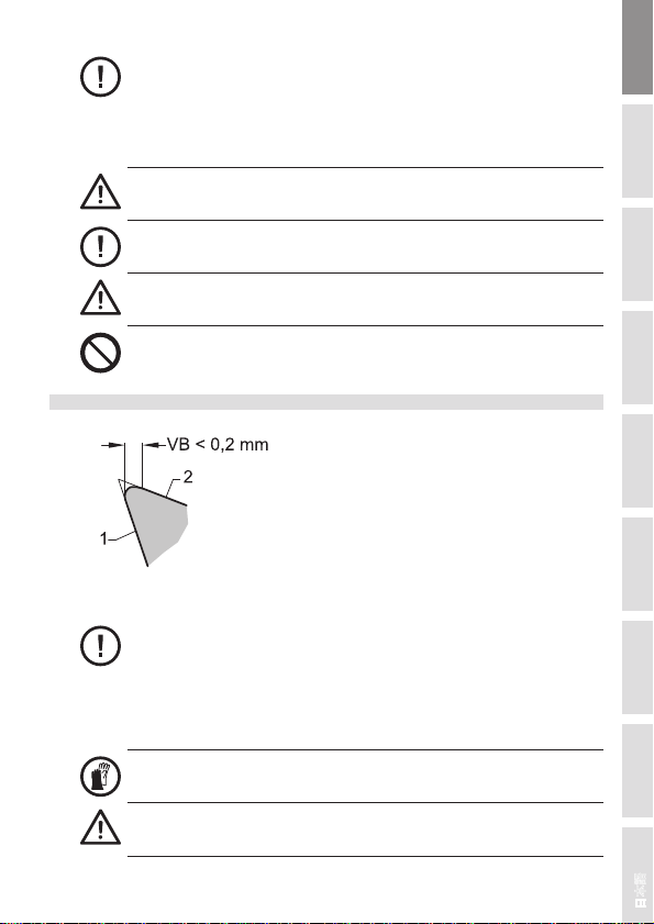
Die regelmäßige Reinigung der Schneiden von Harz und Leim (Aufbauschneiden) erhöht
die Standzeit und die Betriebssicherheit.
Beim Reinigen Hand- und Augenschutz tragen.
Reinigungs ittel können Haut, Augen angreifen und das Werkzeug oder
Spannzeug beschädigen.
Nur Reinigungsmittel verwenden, die das aterial nicht angreifen, z.B. Sur-Tec 194 für
Stahl bzw. Sur-Tec 143 für Aluminium und Stahl.
Reinigungs- und Pflegemittel können beim Werkzeughersteller bezogen werden.
Hinweise des Reinigungsmittelherstellers sind zu beachten.
Holzbearbeitungswerkzeuge und Spannzeuge sind zum Vermeiden von Korrosion vor
Feuchtigkeit zu schützen.
Geeignete Pflegemittel: Universalöle, z.B. WD 40 oder Ballistol
1.6 Instandsetzen, Ändern, Schärfen
1.6.1 Allge eine Forderungen
Instandsetzungsarbeiten und Änderungen dürfen nur vom Hersteller oder von
autorisierten Fachwerkstätten durchgeführt werden.
Gefahr des Werkzeugbruchs.
Es dürfen nur Ersatzteile verwendet werden, die mit den Vorgaben für Originalersatzteile
des Werkzeugherstellers übereinstimmen.
Toleranzen, die ein einwandfreies Spannen sicherstellen, müssen eingehalten werden.
Das Schärfen, Instandsetzen oder Ändern von Werkzeugen darf nur von Fachleuten mit
entsprechender Erfahrung gemäß den Anweisungen des Herstellers durchgeführt
werden.
Die Fachleute müssen vertraut sein mit:
- dem Stand der Technik bezüglich der Konstruktion und Gestaltung
- den nationalen Vorschriften sowie mit
- den einschlägigen Sicherheitsbestimmungen und -normen
- und über die normalen ittel und die Fähigkeiten für diese Arbeiten verfügen.
Nach jedem Schärfen, Instandsetzen oder Ändern muss sichergestellt sein, dass das
Werkzeug die Anforderungen der Europäischen Norm EN 847-1 erfüllt.
Bei Auswirkung der Änderung/ Neubestückung auf die Angaben der
Werkzeugkennzeichnung sind diese zu aktualisieren. Der Name / Logo des der Änderung/
Neubestückung durchführenden Unternehmens ist hinzuzufügen.
1.6.2 Schärfanleitung
Die Schärfanweisung beim Werkzeughersteller anfordern.

DeutschEnglish
日本語中文 ItalianoFrançaiseEspañolPortuguêsРусский
704/2012 ID.524571 V2.0
1 General infor ation
The tool corresponds to the requirements according to EN 847-1.Follow the instruction
manual before using the tool!
1.1 Marking
1. anufacturer
2. ID-No.
3. ax. dimensions (Dmax. x SBmax. x BO)
4. aximum operating RP ’s (n max.)
5. Type of feed
6. Tool description
7. Cutting material
8. Other manufacturer markings
For the application of several tools on a long
planerhead or on a cutter arbour, the smallest
value “n max.” is valid as RP .
1.2 Cutting aterials and ordering details
1.2.1 Cutting Materials
1.2.2
SP = Alloyed tool steel HL = High alloyed tool steel
HS = High speed steel ST = Cast cobalt-based alloys, e.g. stellite
HW = Carbide, uncoated HC = Carbide, coated
DP = Polycrystalline diamond D = onocrystalline diamond
Ordering details
Product name
ID-No.
Dimensions
Number of cutting edges
Type of feed
RP
1.3 Intended use
1.3.1 RPM n / n ax.
The RP range marked “n“ on the tool has to be kept, resp. the specified max. RP “n
max.“ is not allowed to be exceeded!
1.3.2 Usage category and working ethod
Please pay attention to the specifications of the machine manufacturer concerning the
applicability of the tool.
The specified tool is only allowed to be used for the type of feed marked on the tool.

DeutschEnglish
日本語中文 ItalianoFrançaiseEspañolPortuguêsРусский
8 04/2012 ID.524571 V2.0
MEC ( echanical feed)
Tools marked with “ EC“ shall only be used on machines with mechanical feed!
1.3.3 Working ethod
1.3.4 Material to be achined
Wood, wood-based material, as well as material with comparable cutting properties as per
catalogue details. Special applications only after release by the manufacturer.
1.4 Safe handling
1.4.1 Application
The tool is only allowed to be used as described in the section “Intended use”.
The valid national rules for accident prevention and safety at work regulations have to be
observed - especially the safety requirements according to EN 847.
1.4.2 Transport
Wear safety gloves!
Danger of injury by sharp cutting edges!
Transport only with suitable packaging.
Be very careful when packing / unpacking!
Danger of da age!
1.4.3 Mounting on the achine

DeutschEnglish
日本語中文 ItalianoFrançaiseEspañolPortuguêsРусский
904/2012 ID.524571 V2.0
The tool has to be mounted, locked and started up on the machine as per the instructions
of the machine manufacturer.
Starting the machine during the tool change is not allowed (see handling instructions of
the machine).
Wear safety gloves!
Danger of injury by sharp cutting edges!
Before using the tool check the cutting parts, clamping screws and clamping elements for
correct and tight seating.
Danger of injuring fro parts flying off.
The limits for the tool weight, -diameter and projection length recommended by the
machine manufacturer have to been observed.
Check the machine data, especially RP and direction of rotation!
Danger of loosening of the tool.
Unproper stopping of the tool, e.g. by lateral pressing, is not allowed.
During mounting take care, that tool and all cutting and spare parts are mounted on
correct clamping devices.
When using stacked tooling ensure that the cutting parts are not in contact with each
other.
All clamping surfaces have to be free of dirt, grease, oil or water.
Cutting parts shall not come in contact with clamping elements or machine parts.
Tighten clamping screws and nuts by using appropriate mounting tool and the
recommended torque.
The extension of wrenches or the use of ha er blows is not per itted!
1.4.4 Precautions
Check the cutting edges, clamping elements, screws and tool bodies regularly for
potential damages – especially after collision of the tool with parts of the machine e.g.
machine table, work piece clamping elements, dust hood.
Damaged or worn cutting parts, clamping elements or screws have to be set-wise
immediately replaced with original replacement parts.

DeutschEnglish
日本語中文 ItalianoFrançaiseEspañolPortuguêsРусский
10 04/2012 ID.524571 V2.0
Damaged tools have to be checked by an expert.
Danger of injuring fro parts flying off.
Tools with cracked bodies or deformed seating of the cutting parts have to be taken out of
service. Repairing such tools is not allowed!
Danger of tool breakage.
Do not use a defor ed tool.
1.5 Cleaning and Maintenance
1 chip area
2 Clearance face
For reasons of working safety, the cutting tip / cutting edges (see section “Servicing,
modifying, sharpening”) at the latest have to be serviced when:
- the wear mark width VB on the cutting edges amounts to more than 0,2 mm – pay
special attention to the main wear zones.
- break outs of the cutting edge are visible.
- the power consumption of the machine increases noticably.
Wear safety gloves!
Danger of injury by sharp cutting edges!
The cutting edges have to be regularly cleaned from resin and glue (built-up edges) – this
increases the performance time and the operational safety.
Protect hands and eyes while cleaning.

DeutschEnglish
日本語中文 ItalianoFrançaiseEspañolPortuguêsРусский
1104/2012 ID.524571 V2.0
Detergents can irritate skin and eyes and da age the tool or cla ping device.
Only use detergents, which do not corrode the material, e.g.Sur-Tec 194 for steel resp.
Sur-Tec 143 for aluminium and steel.
The appropriate detergents and care products can be obtained from the tool manufacturer
Follow the instructions of the detergent manufacturer.
Woodworking tools and clamping devices are to be protected against humidity in order to
avoid corrosion.Adequate detergents and care products: multi-purpose oil, e.g. WD 40 or
Ballistol
1.6 Servicing, odifying, sharpening
1.6.1 General instructions
Service and modifications are only allowed to be done by the manufacturer or by
authorized professional workshops.
Danger of tool breakage.
Only those replacement parts are allowed to be used, which match the requirements of
the original replacement parts of the tool manufacturer.
Tolerances, that guarantee a precise clamping, have to be kept.
Sharpening, repairing or modifying of tools is only allowed to be done by experienced
specialists as per the instructions of the manufacturer.
Specialists must have knowledge and experience of:
- up-to-date engineering standards in the design and construction of woodworking tools
- national rules and regulations
- relevant safety regulations and standards
- and have the necessary machinery and the required skills to undertake the task
After any sharpening, repairing or modifying, it shall be guaranteed, that the tool meets the
requirements of the European Standard EN 847-1.
Tool labellings, which have been affected by modification / re-tipping, have to be updated.
Name/ logo of the modifying / re-tipping company have to be added.
1.6.2 Sharpening instruction
Ask the tool manufacturer for the sharpening instruction.

DeutschEnglish
日本語中文 ItalianoFrançaiseEspañolPortuguêsРусский
12 04/2012 ID.524571 V2.0
1 Parte co une
L’utensile corrisponde alle richieste della normativa europea EN 847-1.Prima di utilizzare
l’utensile, leggere attentamente il manuale d’uso!
1.1 Marcatura
1. Produttore
2. codice
3. Dimensioni massime (Dmax. x SBmax. x BO)
4. Numero di giri massimo al minuto (n max.)
5. Tipo di avanzamento
6. denominazione utensile
7. ateriali da taglio
8. marcatura aggiuntiva del produttore
Utilizzando diversi utensili su un unico albero o su
un mandrino di fresatura, la velocità operativa è
uguale al valore minimo “n max”.
1.2 Materiali da taglio ed infor azioni riguardanti l’ordine
1.2.1 Materiali da taglio
1.2.2
SP = acciaio per utensile legato HL = aacciaio per utensili altamente
legato
HS = acciaio super rapido ST = stellite - legehe a base di cobalto
HW = metallo duro non rivestito HC = metallo duro rivestito
DP = diamante policristallino D = diamante monocristallino
Infor azioni riguardanti l’ordine
Denominazione del prodotto
codice
Dimensioni
Numero dei taglienti
Tipo di avanzamento
Numeri di giri al minuto
1.3 Modo d’uso
1.3.1 nu ero di giri n / n assi o
Il numero di giri marcato sull’utensile con “n” è tassativamente da rispettare. Il numero di
giri indicato con “n max” non dev’essere superato!
1.3.2 Tipo di applicazione e odo di lavorazione
Prestare attenzione alle specifiche del produttore macchina per quanto riguarda
l’applicabiltà dell’utensile.

DeutschEnglish
日本語中文 ItalianoFrançaiseEspañolPortuguêsРусский
1304/2012 ID.524571 V2.0
L’utensile descritto può essere impiegato solo con il tipo di avanzamento indicato
sull’utensile.
MEC ( avanza ento eccanico)
Gli utensili contrassegnati con “ EC” possono essere usati solo su macchinecon
avanzamento meccanico!
1.3.3 Modo di lavorazione
1.3.4 Materiali che possono essere trattati
Legno, materiale a base di legno, materiale con simili caratteristiche di truciolatura come
indicato nel catalogo.Applicazioni speciali solo dopo l’autorizzazione del produttore.
1.4 L’uso sicuro
1.4.1 Applicazione
L’utensile può essere usato solo come descritto nel capitolo “ odo d’uso”!
Sono da osservare i regolamenti sulla sicurezza sul lavoro e le normative
antinfortunistiche in vigore nel rispettivo paese - specialmente i requisiti di sicurezza
secondo la normativa europea EN 847.
1.4.2 Trasporto
Indossare obbligatoriamente guanti di sicurezza!
Pericolo di lesioni dovuto a taglienti affilati!
Trasporto deve avvenire esclusivamente con imballi idonei allo scopo!
Siate molto attenti quando imballate / disimballate!
Rischio di danni!

DeutschEnglish
日本語中文 ItalianoFrançaiseEspañolPortuguêsРусский
14 04/2012 ID.524571 V2.0
1.4.3 Montaggio sulla acchina
L’utensile deve essere montato, bloccato e utilizzato sulla macchina secondo le istruzioni
del costruttore macchina.
Non è permesso avviare la macchina durante il cambio d’utensile (vedi manuale d’uso).
Indossare obbligatoriamente guanti di sicurezza!
Pericolo di lesioni dovuto a taglienti affilati!
Prima di usare l’utensile controllate il corretto alloggiamento delle parti taglienti, delle viti e
degli elementi di bloccaggio.
Pericolo di lesioni a causa di pezzi proiettati via!
I limiti di peso, diametro e lunghezza dell’utensile raccomandati dal produttore macchina
sono da rispettare.
Controllare i dati forniti dal costruttore, specialmente il numero di giri ed il senso di
rotazione.
Pericolo di sblocco dell’utensile!
Un i proprio arresto dell’utensile non è per esso, p.es. causato da pressioni
laterali .
Controllare durante il montaggio che utensile, parti taglienti e componenti da assemblare
siano ben bloccati nei loro appositi appoggi.
Quando impilate gli utensili assicuratevi che le parti taglienti non entrino in contatto tra di
loro.
Tutte le superfici di bloccaggio devono essere prive di polvere, grasso, olio ed acqua.
Le parti taglienti non devono venire a contatto con gli elementi di bloccaggio o parti della
macchina.
Serrare le viti e i dadi di bloccaggio con apposite chiavi e attenersi alle indicazione in
riguardo all’accoppiamento di serraggio.
E’ vietato usare chiavi di serraggio prolungate o artelli!
1.4.4 Precauzioni

DeutschEnglish
日本語中文 ItalianoFrançaiseEspañolPortuguêsРусский
1504/2012 ID.524571 V2.0
Controllare regolarmente le parti taglienti, gli elementi di bloccaggio, le viti ed il corpo
dell’utensile per individuare eventuali difetti - specialmente dopo urti dell’utensile con parti
della macchina, p.es. tavolo, elementi di bloccaggio pezzo, cuffia di aspirazione
Parti taglienti, elementi di bloccaggio o viti consumati o danneggiati devono essere
sostituiti immediatamente con pezzi di ricambio originali.
Gli utensili danneggiati devono essere controllati da un esperto.
Pericolo di lesioni a causa di pezzi proiettati via!
Utensili con corpo incrinato o con deformazioni del piano di appoggio dei taglienti, devono
essere sostituiti. La riparazione di tali utensili non è permessa.
Pericolo di rottura di utensile.
Non usate un utensile defor ato.
1.5 Cura e anutenzione
1a spoglia superiore
2 spoglia inferiore
Per ragioni di sicurezza, le parti taglienti ( vedi capitolo “Servizio, modifica, affilatura”)
devono essere controllati/sostituiti:
- se l’usura segnata con VB sui taglienti è maggiore di 0,2 mm - osservare specialmente
le principali zone di usura.
- rotture di taglienti sono riscontrabili.
- l’assorbimento di corrente della macchina aumenta considerevolmente.
Indossare obbligatoriamente guanti di sicurezza!
Pericolo di lesioni dovuto a taglienti affilati!

DeutschEnglish
日本語中文 ItalianoFrançaiseEspañolPortuguêsРусский
16 04/2012 ID.524571 V2.0
Le parti taglienti devono essere regolarmente pulite da resina e colla, così si aumenta la
durata vita e la sicurezza dell’utensile.
Proteggete le mani e gli occhi mentre pulite.
I detergenti possono sia irritare la pelle e gli occhi che danneggiare l’utensile o il
siste a di bloccaggio.
Usare solo detergenti che non corrodono il materiale, p.es. Sur-Tec 194 per acciaio e Sur
Tec 143 per alluminio e acciaio.
Rivolgersi al costruttore di utensile per ottenere i prodotti idonei per la cura e la
manutenzione degli utensili.
Seguite le istruzioni del produttore del detergente.
Gli utensili e i sistemi di bloccaggio devono essere protetti contro l’umidità per evitare la
corrosione, utilizzando prodotti ed olii appropriati.
1.6 Servizio, odifica, affilatura
1.6.1 Istruzioni generali
anutenzione e modifiche devono essere effettuate soltanto o dal produttore o da
un’officina autorizzata.
Pericolo di rottura di utensile.
Possono essere utilizzati solo pezzi di ricambio originali.
È da attenersi alle tolleranze che garantiscono un preciso bloccaggio.
L’affilatura, la manutenzione e la modifica dell’utensile devono essere eseguite solo da
persone qualificate seguendo le istruzioni del produttore.
Lo specialista dev’essere:
- all’avanguardia in riguardo a costruzione e design
- competente nelle norme e regolamenti nazionali
- conoscere i regolamenti e le norme antinfortunistiche
- Inpiù deve disporre di una formazione e facoltà idonee ad eseguire questi lavori
Dopo ogni affilatura, manutenzione e modifica, bisogna assicurarsi che l’utensile abbia i
requisiti richiesti dalla normativa europea EN 847-1.
I dati del codice dell’utensile sono da aggiornare se in seguito ad una modifica/riaffilatura
non siano più coerenti.Deve essere aggiunto il nome e il logo della ditta che ha eseguito la
modifica / la riaffilatura.
1.6.2 Istruzioni di affilatura
Richiedere al produttore dell’utensile le istruzioni di affilatura.

DeutschEnglish
日本語中文 ItalianoFrançaiseEspañolPortuguêsРусский
1704/2012 ID.524571 V2.0
1 Partie co une
L’outil répond aux exigences de la norme EN 847-1. Avant mise en route, lire attentivement
la notice.
1.1 Désignation
1. Fabricant
2. Code
3. Dimension maximale (Dmax. x SBmax. x BO)
4. Vitesse de rotation maxi (n max.)
5. Type d’avance
6. Désignation d’outil
7. atériaux de coupe
8. Autre désignation du fabricant
Lors d’application de plusieurs outils sur un
même arbre, choisir la vitesse de rotation la
plus basse comme vitesse de rotation
effective d’utilisation.
1.2 Matériaux de coupe et spécifications de co ande
1.2.1 Matériau de coupe
1.2.2
SP = Acier allié HL = Acier à haute teneur en alliage
HS = Acier rapide allié ST = Stellite
HW = Carbure HC = Carbure, revêtu
DP = Diamant polycristallin D = Diamant monocristallin
Spécifications de co ande
Désignation de l’article
Code
Dimensions
Nombre de coupes
Type d’avance
Vitesse de rotation
1.3 Utilisation confor é ent à l’usage
1.3.1 Vitesse de rotation n / n ax.
Respecter la plage de vitesse de rotation “n”spécifiée sur l’outil et ne pas dépasser la
vitesse de rotation maximale “n max” indiquée !
1.3.2 Type d’utilisation et éthode de travail
Respecter les consignes du fabricant de machine concernant la capacité de l’outil.
L’outil décrit ici ne peut être utilisé que conformément au type d’avance.

DeutschEnglish
日本語中文 ItalianoFrançaiseEspañolPortuguêsРусский
18 04/2012 ID.524571 V2.0
MEC (avance écanique)
Les outils marqués “ EC” ne peuvent être utilisés que sur des machines à avance
mécanique!
1.3.3 Type d’usinage
1.3.4 Matériaux à usiner
Bois, dérivés du bois, de même que d’autres matériaux ayant des caractéristiques
d’usinage identiques, selon les données du catalogue. odes d’usinages particuliers
uniquement après acceptation du fabricant.
1.4 Manipulation en toute sécurité
1.4.1 Utilisation
N’utiliser l’outil que dans les conditions décrites dans le paragraphe “Utilisation en fonction
de l’usage”.
Respecter les consignes de prévention des accidents et de protection des travailleurs
propres à chaque pays - en particulier les consignes de sécurité de la norme EN 847.
1.4.2 Transport
Porter des gants de sécurité!
Risque de blessure sur les coupes tranchantes!
Transport uniquement dans l’emballage approprié!
Emballer et déballer avec le plus grand soin!
Risque de détérioration!
1.4.3 Montage sur la achine

DeutschEnglish
日本語中文 ItalianoFrançaiseEspañolPortuguêsРусский
1904/2012 ID.524571 V2.0
L’outil doit être monté, serré et mis en route suivant les prescriptions du fabricant machine.
Condamner la mise en route de la machine pendant le changement d’outil (voir notice de
la machine).
Porter des gants de sécurité!
Risque de blessure sur les coupes tranchantes!
Avant mise en service de l’outil, contrôler que les coupes, les vis de serrage et les
éléments de serrage soient en bonne position.
Risque de blessure par éjection de pièces!
Respecter les valeurs maximales indiquées par la fabricant machine relatives au poids, au
diamètre, au dépassement d’outil.
Contrôler les réglages machine, notamment la vitesse et le sens de rotation.
Risque de desserrage de l’outil!
Un freinage non approprié de l’outil, par ex. par un frotte ent latéral, est interdit.
Lors du montage, il faut s’assurer que l’outil ainsi que tous les couteaux et éléments de
montage soient serrés sur les surfaces d’appui prévues à cet effet.
Pour des outils empilés les uns sur les autres, contrôler que les coupes n’entrent pas en
collision.
Toutes les surfaces d’appui doivent être exemptes de salissures, d’huile, de graisse ou
d’eau.
Les coupes ne doivent pas entrer en contact avec des éléments de fixation et avec des
parties machine.
Serrer les vis ou les écrous de fixation avec l’outil de montage correspondant, ou avec le
couple de serrage approprié!
Serrer les vis ou les écrous de fixation avec l’outil de ontage correspondant, ou
avec le couple de serrage approprié! L’utilisation de rallonges ou d’outillage à
frapper est à proscrire!
1.4.4 Mesures de précaution
Contrôler régulièrement les éventuelles détériorations sur les coupes, les éléments de
serrage, les vis et le corps d’outil , en particulier après une collision de l’outil avec des
éléments machine comme par ex. la table, des éléments de serrage, aspiration.

DeutschEnglish
日本語中文 ItalianoFrançaiseEspañolPortuguêsРусский
20 04/2012 ID.524571 V2.0
Les parties coupantes, les éléments de serrage ou les vis endommagés ou usés doivent
être immédiatement - et par jeu complet - échangés contre des pièces d’origine.
Les outils endommagés doivent être contrôlés par un spécialiste.
Risque de blessure par éjection de pièces!
Réformer tout outil ayant un corps fissuré ou des sièges déformés. La réparation d’un tel
outil n’est pas autorisée!
Risque de rupture d’outil.
Ne pas utiliser un outil défor é.
1.5 Nettoyage et entretien
1 Face d’attaque
2 Face de dépouille
Pour des raisons de sécurité du travail, les plaquettes ou coupes sont à remettre en état
(voir paragraphe “Affûtage, entretien, changement”) au plus tard lorsque:
- la zone d’usure est supérieure à 0,2 mm - contrôler surtout la zone d’usure principale.
- l’apparition de brêches sur la coupe.
- la prise d’intensité augmente nettement.
Porter des gants de sécurité!
Risque de blessure sur les coupes tranchantes!
Le nettoyage régulier des coupes (enlèvement de résine et de colle) augmente la durée
de coupe et la sécurité au travail.
Lors du nettoyage, se protéger les yeus et les mains.
Table of contents
Languages:
Other LEITZ Industrial Equipment manuals
Popular Industrial Equipment manuals by other brands

MyBinding
MyBinding Paitec ES7000 instruction manual

Canon
Canon Die Bonder BESTEM-D01 manual

Graco
Graco PR-X Setup - Operation - Repair

HappyJapan
HappyJapan HCD3 Instruction book

Abbey Machinery
Abbey Machinery VF1500T Maintenance, Operating Instructions and Spare Parts Lists

Crane
Crane Barnes 3SE-DS Series Installation and operation manual

ABB
ABB HT608450 Operation manual

Dungs
Dungs GasMultiBloc MB-D B01 Operation and assembly instructions

Nilfisk-Advance
Nilfisk-Advance T75 Instructions for use

Honeywell
Honeywell HS-700 Description and installation manual

ITALVIBRAS GIORGIO SILINGARDI
ITALVIBRAS GIORGIO SILINGARDI MICRO M3/4 Technical handbook

ABB
ABB HT570736 Operation manual