LEITZ VariPlan Plus User manual

104/2012 ID.524660 V1.0
Deutsch
En lish
日日本本語語中文 Italiano
Français
Español
Portu uês
Русский
Betrie sanleitung - VariPlan Plus
User manual - VariPlan Plus
Li retto d’istruzione - VariPlan Plus
Manuel d’utilisation - VariPlan Plus
Instrucciones de servicio - VariPlan Plus
Instruções de utilização - VariPlan Plus
Руководство по эксплуатации - VariPlan Plus
使用手册-VariPlan Plus取扱説明書 - ヴァリプランプラス
2 04/2012 ID.524660 V1.0
Deutsch
En lish
日日本本語語中文 Italiano
Français
EspañolPortu uês
Русский
1 All emeiner Teil
Das Werkzeug entspricht den Anforderungen gemäß EN 847-1. Vor In etrie nahme des
Werkzeuges ist die Betrie sanleitung zu eachten!
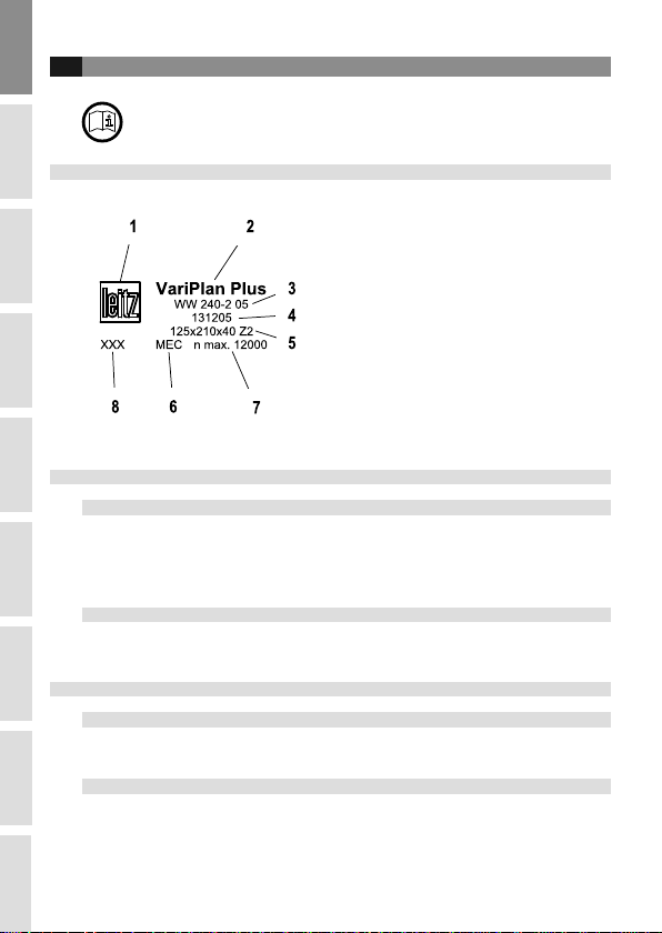
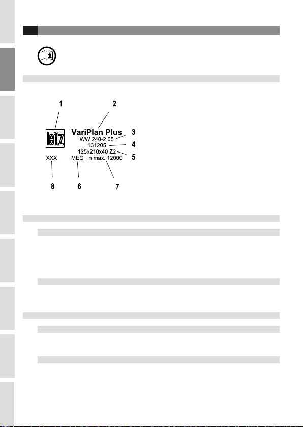
1.1 Kennzeichnun
1. Hersteller
2. Werkzeug ezeichnung
3. Artikel-Nr.
4. Ident-Nr.
5. Maximale A messung (Dmax x SBmax x BO)
6. Vorschu art
7. Maximale Betrie sdrehzahl (n max)
8. Weitere Kennzeichnung des Herstellers
Bei Verwendung mehrerer Werkzeuge auf einer
Welle zw. einem Fräsdorn, gilt der kleinste Wert
“n max.” als Betrie sdrehzahl.
1.2 Schneidstoffe und Bestellan aben
1.2.1 Schneidstoffe
1.2.2
SP = Werkzeugstahl, legiert HL = Werkzeugstahl, hochlegiert
HS = Schnellar eitsstahl, hochlegiert ST = Stellit
HW = Hartmetall, un eschichtet HC = Hartmetall, eschichtet
DP = Polykristalliner Diamant DM = Monokristalliner Diamant
MC = Mehr ereichsstahl, eschichtet
Bestellan aben
Artikel ezeichnung
Ident-Nummer
A messungen
Schneidenzahl
Vorschu art
Drehzahl
1.3 Bestimmun s emäßer Gebrauch
1.3.1 Drehzahl n / n max.
Der auf dem Werkzeug angege ene Drehzahl ereich “n“ muss eingehalten werden zw.
die angege ene Höchstdrehzahl “n max.“ darf nicht ü erschritten werden!
1.3.2 Verwendun sart und Arbeitsweise
Die Vorga en des Maschinenherstellers ezüglich der Eignung des Werkzeuges sind zu
eachten.
Das hier eschrie ene Werkzeug darf nur entsprechend der Kennzeichnung der
Vorschu art verwendet werden.

304/2012 ID.524660 V1.0
Deutsch
En lish
日日本本語語中文 Italiano
Français
Español
Portu uês
Русский
MEC (Mechanischer Vorschub)
Mit „MEC“ gekennzeichnete Werkzeuge dürfen nur auf Maschinen mit mechanischem
Vorschu verwendet werden!
MAN (Handvorschub)
Mit „MAN“ gekennzeichnete Werkzeuge dürfen auch auf Maschinen mit mechanischem
Vorschu verwendet werden!
Gleichlauf: Verboten we en Rückschla efahr!
1.3.3 Bearbeitun sart
1.3.4 Zu bearbeitende Werkstoffe
Holz, Holzwerkstoffe sowie Werkstoffe mit vergleich aren Zerspanungseigenschaften,
gemäß Kataloganga en.
Spezielle Anwendungszwecke nach Freiga e durch den Hersteller.
1.4 Sicherer Um an
1.4.1 Verwendun
Das Werkzeug darf nur wie in A schnitt „Bestimmungsgemäßer Ge rauch“ eschrie en,
eingesetzt werden!
Es sind die jeweils gültigen nationalen Unfallverhütungs- und Ar eitsschutzvorschriften
einzuhalten - ins esondere die sicherheitstechnischen Anforderungen nach EN 847-1.
1.4.2 Transport
Schutzhandschuhe tragen!

4 04/2012 ID.524660 V1.0
Deutsch
En lish
日日本本語語中文 Italiano
Français
EspañolPortu uês
Русский
Verletzun s efahr durch scharfe Schneiden!
Transport nur in geeigneter Verpackung!
Beim Ein-/ Auspacken ist äußerste Sorgfalt anzuwenden!
Beschädi un s efahr!
1.4.3 Zusammenbau des Werkzeu s
Schutzhandschuhe tragen!
Verletzun s efahr durch scharfe Schneiden!
Immer alle Teile montieren. Baugleiche Teile müssen gewichtsgleich sein, um Unwuchten
zu vermeiden.
Schneidteile, Schneidenaufnahmen und Spannelemente müssen frei von
Verschmutzungen, z.B. Harz, Fett, Öl oder Wasser, sein.
Schrau enköpfe müssen gereinigt werden, um einen korrekten und festen Sitz des
zugehörigen Montagewerkzeuges zu gewährleisten.
Verletzun s efahr durch we flie ende Teile!
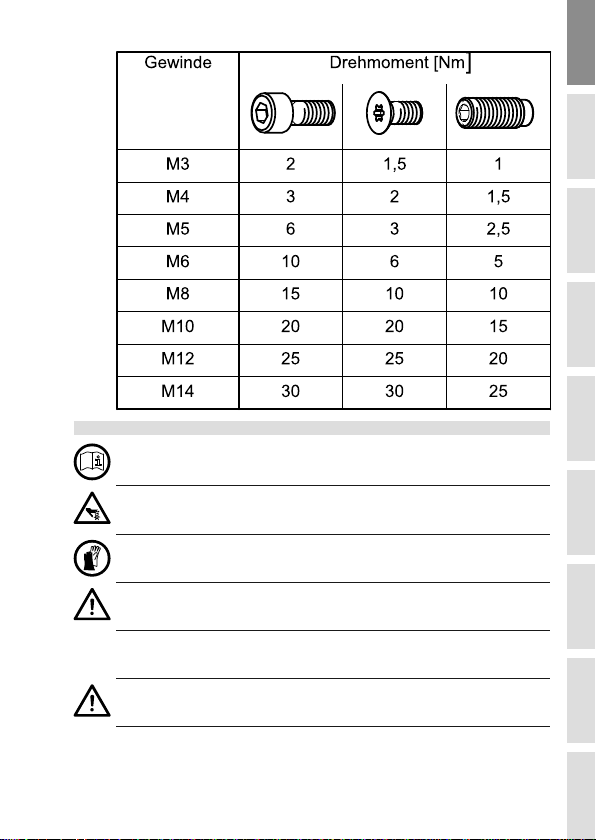
Spannschrau en und -muttern mit dem zugehörigen Montagewerkzeug zw. mit dem
vorgege enen Drehmoment anziehen.
Das Verlän ern von Spann-Schlüsseln oder die Verwendun von
Schla werkzeu en ist verboten!
Sofern nicht gesondert angege en, gelten folgende Drehmomente:
504/2012 ID.524660 V1.0
Deutsch
En lish
日日本本語語中文 Italiano
Français
Español
Portu uês
Русский
1.4.4 Monta e auf der Maschine
Das Werkzeug ist gemäß den Vorga en des Maschinenherstellers auf der Maschine zu
efestigen, zu sichern und in Betrie zu nehmen.
Das Anlaufen der Werkzeugmaschine während des Werkzeugwechsels ist
auszuschließen (siehe Betrie sanleitung der Maschine).
Schutzhandschuhe tragen!
Verletzun s efahr durch scharfe Schneiden!
Vor In etrie nahme des Werkzeuges Schneidteile, Spannschrau en und Spannelemente
auf richtigen und festen Sitz ü erprüfen.
Verletzun s efahr durch we flie ende Teile!
Die vom Maschinenhersteller vorgege enen Höchstwerte für die Werkzeugmasse, -
durchmesser und Auskraglänge müssen eingehalten werden.
6 04/2012 ID.524660 V1.0
Deutsch
En lish
日日本本語語中文 Italiano
Français
EspañolPortu uês
Русский
Maschineneinstellungen, ins esondere Drehzahl und Drehrichtung, kontrollieren!
Gefahr des Lösens des Werkzeu es!
Unsach emäßes Abbremsen des Werkzeu es, z.B. durch seitliches Andrücken, ist
nicht zulässi .
Bei der Montage muss sichergestellt werden, dass das Werkzeug sowie alle Schneiden-
und Ein auteile auf den dafür vorgesehenen Spannflächen gespannt sind.
Die Schneiden dürfen nicht mit Befestigungsmitteln oder Maschinenteilen in Berührung
kommen.
Bei aufeinander gesetzten Werkzeugen ü erprüfen, dass sich die Schneiden nicht
gegenseitig erühren.
Alle Spannflächen müssen frei von Verschmutzungen, Fett, Öl oder Wasser sein.
Spannschrau en und -muttern mit dem zugehörigen Montagewerkzeug zw. mit dem
vorgege enen Drehmoment anziehen.
Das Verlän ern von Spann-Schlüsseln oder die Verwendun von
Schla werkzeu en ist verboten!
1.4.5 Vorsichtsmaßnahmen
Schutzhandschuhe tragen!
Verletzun s efahr durch scharfe Schneiden!
Gehörschutz tragen!
Risiko der Erkrankun an Schwerhöri keit!
Schneidteile, Spannelemente, Schrau en und Werkzeug-Grundkörper regelmäßig auf
mögliche Beschädigungen ü erprüfen – ins esondere nach einer Kollision des
Werkzeuges mit Maschinenteilen z.B. Maschinentisch, Werkstückspannelementen,
A saughau en.
Beschädigte oder verschlissene Schneidteile, Spannelemente oder Schrau en müssen
sofort satzweise gegen Originalteile ausgetauscht werden.
Beschädigte Werkzeuge sind von einem Fachmann zu ü erprüfen.
Verletzun s efahr durch we flie ende Teile!
Werkzeuge mit gerissenen Grundkörpern oder deformierten Schneidenaufnahmen
müssen ausgemustert werden. Das Instandsetzen oder Reparieren dieser Werkzeuge ist
nicht erlau t!
704/2012 ID.524660 V1.0
Deutsch
En lish
日日本本語語中文 Italiano
Français
Español
Portu uês
Русский
Gefahr des Werkzeu bruchs.
Ein deformiertes Werkzeu darf nicht ein esetzt werden.
1.5 Reini un und Pfle e
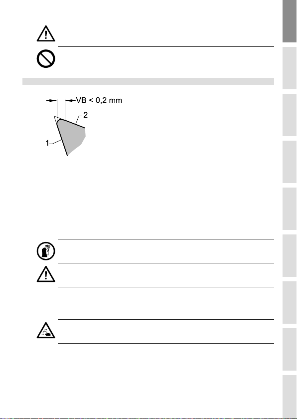
1 Spanfläche
2 Freifläche
Aus Gründen der Ar eitssicherheit sind die Schneidplatten / Schneiden instand zu setzen
(siehe A schnitt „Schärfen, Instandsetzen, Ändern“), spätestens wenn:
- die Verschleißmarken reite VB an den Schneiden größer 0,2 mm eträgt - esonders
die Hauptverschleißzonen eachten.
- Schneidenaus rüche erkenn ar sind.
- die Stromaufnahme der Maschine merklich ansteigt.
Schutzhandschuhe tragen!
Verletzun s efahr durch scharfe Schneiden!
Die regelmäßige Reinigung der Schneiden von Harz und Leim (Auf auschneiden) erhöht
die Standzeit und die Betrie ssicherheit.
Beim Reinigen Hand- und Augenschutz tragen.
Reini un smittel können Haut, Au en an reifen und das Werkzeu oder
Spannzeu beschädi en.
Nur Reinigungsmittel verwenden, die das Material nicht angreifen, z.B. Sur-Tec 194 für
Stahl zw. Sur-Tec 143 oder Avilu METACLEAN 788 für Aluminium und Stahl.
Reinigungs- und Pflegemittel können eim Werkzeughersteller ezogen werden.
Hinweise des Reinigungsmittelherstellers sind zu eachten.

8 04/2012 ID.524660 V1.0
Deutsch
En lish
日日本本語語中文 Italiano
Français
EspañolPortu uês
Русский
Holz ear eitungswerkzeuge und Spannzeuge sind zum Vermeiden von Korrosion vor
Feuchtigkeit zu schützen. Geeignete Pflegemittel: Universalöle, z.B. WD 40 oder Ballistol
1.6 Instandsetzen, Ändern, Schärfen
1.6.1 All emeine Forderun en
Instandsetzungsar eiten und Änderungen dürfen nur vom Hersteller oder von
autorisierten Fachwerkstätten durchgeführt werden.
Gefahr des Werkzeu bruchs.
Es dürfen nur Ersatzteile verwendet werden, die mit den Vorga en für Originalersatzteile
des Werkzeugherstellers ü ereinstimmen.
Toleranzen, die ein einwandfreies Spannen sicherstellen, müssen eingehalten werden.
Das Schärfen, Instandsetzen oder Ändern von Werkzeugen darf nur von Fachleuten mit
entsprechender Erfahrung gemäß den Anweisungen des Herstellers durchgeführt
werden.
Die Fachleute müssen vertraut sein mit:
- dem Stand der Technik ezüglich der Konstruktion und Gestaltung
- den nationalen Vorschriften sowie mit
- den einschlägigen Sicherheits estimmungen und -normen
- und ü er die normalen Mittel und die Fähigkeiten für diese Ar eiten verfügen.
Nach jedem Schärfen, Instandsetzen oder Ändern muss sichergestellt sein, dass das
Werkzeug die Anforderungen der Europäischen Norm EN 847-1 erfüllt, ins esondere
hinsichtlich:
904/2012 ID.524660 V1.0
Deutsch
En lish
日日本本語語中文 Italiano
Français
Español
Portu uês
Русский
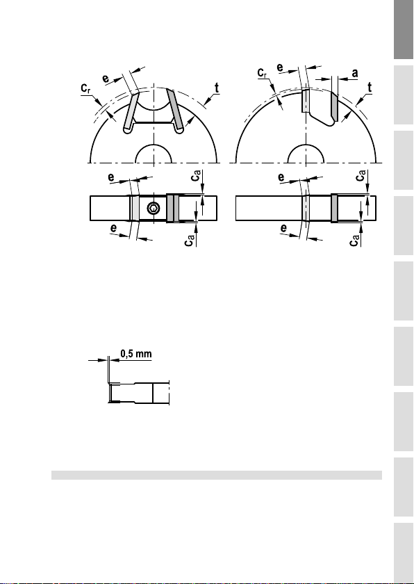
- Auswuchtgüte
- Schneidplattendicke a
- Schneidplatten-Ü erstand cr, ca, t
- Breite der A weisfläche e
Ü erstand der Vorschneider
Bei Auswirkung der Änderung / Neu estückung auf die Anga en der
Werkzeugkennzeichnung sind diese zu aktualisieren. Der Name / Logo des die Änderung /
Neu estückung durchführenden Unternehmens ist hinzuzufügen.
1.6.2 Schärfen
Die Schärfanweisung eim Werkzeughersteller anfordern.
Deutsch
En lish
日日本本語語中文 Italiano
Français
EspañolPortu uês
Русский
10 04/2012 ID.524660 V1.0
1 General information
The tool corresponds to the requirements according to EN 847-1. Follow the instruction
manual efore using the tool!
1.1 Markin
1. Manufacturer
2. Tool description
3. Article num er
4. ID-No.
5. Max. dimensions (Dmax. x SBmax. x BO)
6. Type of feed
7. Maximum operating RPM’s (n max.)
8. Other manufacturer markings
For the application of several tools on a long
planerhead or on a cutter ar our, the smallest
value “n max.” is valid as RPM.
1.2 Cuttin materials and orderin details
1.2.1 Cuttin Materials
1.2.2
SP = Alloyed tool steel HL = High alloyed tool steel
HS = High speed steel ST = Cast co alt- ased alloys, e.g. stellite
HW = Car ide, uncoated HC = Car ide, coated
DP = Polycrystalline diamond DM = Monocrystalline diamond
MC = Multi purpose steel, coated
Orderin details
Product name
ID-No.
Dimensions
Num er of cutting edges
Type of feed
RPM
1.3 Intended use
1.3.1 RPM n / n max.
The RPM range marked “n“ on the tool has to e kept, resp. the specified max. RPM “n
max.“ is not allowed to e exceeded!
1.3.2 Usa e cate ory and workin method
Please pay attention to the specifications of the machine manufacturer concerning the
applica ility of the tool.
The specified tool is only allowed to e used for the type of feed marked on the tool.
Table of contents
Languages:
Other LEITZ Industrial Equipment manuals


