Lekla PIVO User manual

SOLAR ENERGY STATION
INSTALLATION
MANUAL

Page 2 of 11
■Lifting and storage base
■Charge storage batteries
■Electrical and solar cabling
■Electrical and electronic connection
components
■Controller
■Pole
■Lamp and/or other accessories (e.g. camera)
■Solar panel support system
■Solar panel
INTRODUCTION
IMPORTANT !
The PIVO | LEKLA multi-purpose autonomous solar energy
station you have purchased has various components, some of
which are pre-assembled, while others require assembly directly
at the installation site.
Please carefully read this installation guide, it contains
important information and notes regarding the installa-
tion and start-up of your PIVO | LEKLA multi-purpose
autonomous solar energy station.
A certified technician (electrician, engineer) must install
this product in accordance with the applicable electrical
and building codes.
Do not modify the structure or any of the components of
this product.
Make sure you have the latest version of this installation
guide. If in doubt, visit our web site lekla.ca or contact
us at LEKLA 819-769-0350.

Page 3 of 11
DANGER !
Safety Warning
Although the electrical voltages present are low (less than 50 V), the electrical current gene-
rated by the batteries can be several hundred amperes.
Safety devices have been provided for this product. However, improper handling of this
product could cause injury or material damage to the various components).
Ensure that handling and installation of the PIVO | LEKLA Multi-Purpose Energy Station is
carried out by qualified technicians.

Page 4 of 11
ITEM NO DESCRIPTION POIDS UNITAIRE
kg / lb QUANTITÉ
1Lifting and storage base includes 4 to 6 12 V batteries,
controller and interconnection wiring to the pole 500 / 1100 1
2 Pole, includes the interconnection wiring between the base and various equipment 96 / 212 1
3 Other accessories (see purchase slip) 6,4 / 14 1
4 Other accessories (see purchase slip)
5 Solar panel support includes wiring to the pole 8 / 18 1
6 Solar panel, includes U-bolts and brackets 19 / 42 1
7 Lifting eye nuts 2
*Should a part be missing, please call 819-769-0350.
STEP 1
BEFORE INSTALLATION: IDENTIFICATION OF EACH GROUP OF ELEMENTS,
AS WELL AS THE PARTS THAT COMPOSE THEM
Verify and count each part included with your PIVO | LEKLA Multi-Purpose Energy Station according to the following check-list :
STEP 2
SOIL PREPARATION AND GROUNDING THE BASE OF THE PIVO | LEKLA MULTI-PURPOSE
AUTONOMOUS SOLAR ENERGY STATION (PART No. 1)
Figure 2
Hoisting points
____________
Figure 1: Top view of the lifting and storage base with lifting eye nuts
Figure 2: Lifting and storage base as a whole. System weight of 500 kg/1100 lbs
IMPORTANT! Proper base grounding of the PIVO | LEKLA Multi-Purpose Autonomous Energy Station is
essential to ensure that the energy station is safe. The installer (contractor) is responsible of determine a base
grounding and installation procedure that complies with current standards and to refer to a geotechnical study if
required.
To ensure safe hoisting of the lifting and storage
base, use at least 2 of the 4 3/4-10 UNC threaded
rods that serve as an anchor point to the pole. It is
recommended that two lifting eye nuts with 3/4-10
UNC threads and a suitable sling be placed on two
threaded rods.
Refer to Figure 1 for choice of hoisting points.
Figure 1

Page 5 of 11
SOIL PREPARATION PRIOR TO DIGGING
DIGGING OR EXCAVITING RECOMMENDATIONS FOR THE INSTALLATION
OF THE LIFTING AND STORAGE BASE
IMPORTANT:
To avoid breakage or malfunction, handle the lifting system with care as it contains the assembled batteries
and control box.
Prior to digging or excavating the ground for the PIVO | LEKLA Multi-Purpose Autonomous Energy Station, make sure
that its installation does not compromise or alter in any way the integrity of existing power lines or underground
equipment on site and that the work can be carried out in complete safety, without risk of electrocution, explosion,
leakage or collapse.
It is therefore your duty to inform yourself of the presence of underground pipes (sewer, water, gas, etc.), electricity,
telephone lines, tv cable by contacting the agencies concerned. If the work is carried out near a surface drain or
manhole, make sure to inform yourself with competent services that the installation of the PIVO | LEKLA will in no
way alter them.
Finally, if the work is carried out near overhead and/or underground power lines, make sure, before starting the work,
to secure the perimeter if necessary and provide a safe distance for your equipment to avoid any risk of electrocution.
NOTE :
Location of the base of the Autonomous Energy Station and identification of the type of soil are the responsi-
bility of the client and in no case the responsibility of LEKLA.
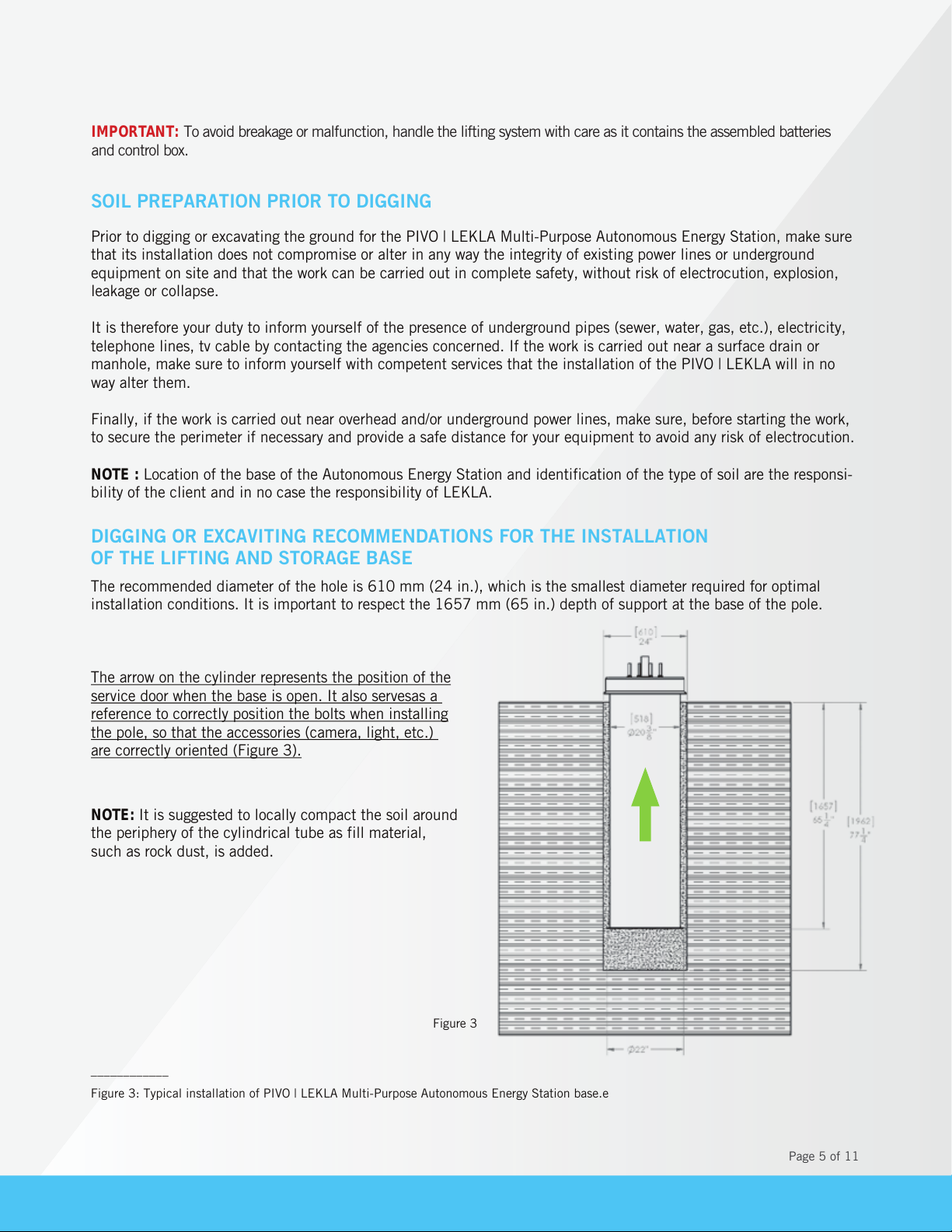
The recommended diameter of the hole is 610 mm (24 in.), which is the smallest diameter required for optimal
installation conditions. It is important to respect the 1657 mm (65 in.) depth of support at the base of the pole.
The arrow on the cylinder represents the position of the
service door when the base is open. It also servesas a
reference to correctly position the bolts when installing
the pole, so that the accessories (camera, light, etc.)
are correctly oriented (Figure 3).
NOTE:
It is suggested to locally compact the soil around
the periphery of the cylindrical tube as fill material,
such as rock dust, is added.
Figure 3
____________
Figure 3: Typical installation of PIVO | LEKLA Multi-Purpose Autonomous Energy Station base.e

Page 6 of 11
STEP 3
POLE PREPARATION
1.
2.
Figure 5
Place a beam at the base of the pole and attach two 3/4-10
X 4 in. long bolts to hold it in position and stabilize it on the
trestle (Figure 4). With the top end raised, it is easier to join
the components without risk of damaging them.
Unscrew the cover of the service door located at the bottom
of the pole with the locking key. It will serve as a connection
point for the wiring (Figure 5).
Figure 4

Page 7 of 11
3.
STEP 4
LUMINAIRE ATTACHMENT TO THE POLE
(Part No. 3 optional)
____________
Figure 7 : Positioning the luminaire on the end of the 60 mm (2-3/8 in.) diameter connecting tube
Fixing the luminaire is facilitated as the end of the tube
for its connection is within easy reach. Untie the cable
coming out of the arm for the luminaire and connect
the cable from the arm to the luminaire. Push the wire
back inside the arm making a loop (Figure 7.1) to
create a loose in the wires. This loop will make it easier
to disconnect the luminaire if necessary (Figure 7).
Figure 7
Example of a wire loop in the arm
Figure 6
Remove the protective membrane covering the support and the panel; pass all wiring through the top opening
of the pole. The solar panel wiring (black/white wire pair) should reach the service opening at the base of the
pole. Insert the solar panel support into the pole, being careful not to pinch the wires (Figure 6).

Page 8 of 11
STEP 5
SOLAR PANEL ELEVATION ANGLE ADJUSTMENT* (Part No.6)
STEP 6
AZIMUTH 180° ADJUSTEMENT, SOUTH-FACING (Part No.6)*
Angle with respect to an horizontal plan
xample of 180° between the arm and the face of the solar
panel (arm faces north and the solar panel faces south.)
Make sure that the panel is at an angle of 55 to 60° with respect to an horizontal plane as if the pole were
standing vertically and the wires were falling towards the base of the pole. Then tighten the U-bolts to lock it in
place. The angle suggested is suitable for most regions of Quebec, see the project data sheet or contact LEKLA for
more information on the location of the installation (Figure 8).
It is possible to use the website www.suncalc.org to simulate the sun’s position in relation to the location of your
solar installation and to see if there are any surrounding obstacles that could affect it, given the differences the
sun’s position at different times of the year.
According to the geographical location of the installation, the angle between the arm or the side of the opening
and the solar panel must be adjusted so that the solar panel faces south. Secure the hexagonal nuts to fix the
support to the pole and connect the wires between the support and the panel (Figures 9 and 10).
Figure 8
Figure 9
Figure 10
Direction of the arm
or of the opening side
South-facing
Angle of the arm in respect to the panel
N
S
O E
*N. B. If the installation is done from a bucket truck, it is possible to make these adjustments once
the pole is installed.

Page 9 of 11
STEP 7
PLACING THE POLE ON ITS BASE
Remove the two lifting eye nuts located on top of the lifting and storage base to allow positioning of the pole. Then
place four locknuts, four 3/4-10 UNC nuts on the threaded rods followed by four 3/4" flat washers (Figure 11 and
12).
Once the pole is assembled, take out the cables through the service door; the red/black wire pair from the batte-
ries, the white/black wire pair from the solar panel and the cable for each of the equipment (for the equipment,
refer to the list on the custom diagram of your PIVO | LEKLA). Then place a sling around the pole at the junction of
the pole or at the balance point, if there is no pole. Lift the pole with lifting equipment. Once the pole is lifted off
the ground and held in a nearly vertical position, remove the beam attached to the base of the pole.
Figure 12
Figure 11
____________
Figure 11 : Top view of the lifting and storage base with the addition of 4 clamping nuts 3/4-10 UNC on the threaded rods.
Figure 12 : Top view of the lifting and storage base with 3/4-10 UNC clamping nuts on the threaded rods and the assembled pole.
Level the pole by its base.

Page 10 of 11
STEP 8
INSTALLATION OF THE POLE AND BASE COVER
STEP 9
LIFTING THE BASE FOR START-UP
STEP 10
VOLTAGE CONTROL CHECK PRIOR TO START-UP
STEP 11
ANTENNA INSTALLATION FOR THE CONTROLLER (INTERNAL OR EXTERNAL) -
for the option equipped with a remote interactive controller
Bring the pole closer to the fixing bolts. Carefully unpack the wires from the lifting base and insert them into the
pole by leading them out through the service door.
Once all the wires have been inserted, carefully mount the pole vertically, making sure not to pinch the wires.
Fasten with four 3/4 in. flat washers followed by four 3/4-10 UNC nuts and four locknuts on the threaded rods.
Level the pole before firmly tightening to secure it in place. Position the base cover.
Connect the hydraulic hoses to the pump and carry out the lifting procedure making sure that the components
included in the base and/or the control box have not been damaged during transport or installation. Make sure that
the red/black, orange/black and yellow/black connector pairs are not connected to the controller in the control box.
Check for voltage on the white/black wire pairs coming from the solar panel using a multimeter. It should be more
than 30 V. On the red/black wire pair equipped with a fuse holder, install the 20 A fuse. Measure the battery
voltage with a multimeter. It should be around 25 V.
If the voltage readings meet the requirements, place the 5 A fuse(s) on the accessory cables and connect the two
red/black wire pairs, the two white/black wire pairs and the accessory connector(s) to each other according to their
identification label.
If the controller is supplied with an internal antenna (small black T about 4 in.), remove the backing paper from
the adhesive behind the antenna and attach the antenna as high as possible to the inside of the pole.
If the controller is supplied with an external antenna, the coaxial cable (black wire with gold connector) must be
fed through the PIVO freestanding base using an electrician fish tape and connected to the controller using the
cable clamp pre-installed on the control box.

Page 11 of 11
STEP 12
STARTING THE CHARGE CONTROLLER
STEP 13
END OF INSTALLATION AND START-UP
YOUR PIVO LEKLA MULTI-PURPOSE AUTONOMOUS ENERGY STATION IS NOW FUNCTIONAL.
Connect the cables to the controller in the following order:
The connectors of the red/black wire pair on the batteries, the orange/black wire pair on Load 1 and/or Load 2
according to the identification label and the yellow/black wire pair on Solar 1.
In the event of a disconnection, please proceed in the reverse order.
If everything is working correctly, the green battery LED indicator and the Solar 1 LED indicator will light up.
The diagram below displays and identifies all the LED indicators.
At this stage, the PIVO | LEKLA should be functional. It will be possible to remotely perform a variety of tests and
to generate management reports from the ILLUMIENCE web site of ClearBlue technologies.
In case of problems, contact the LEKLA service center at 819-769-0350

POLE LIFTING PROCEDURE
ANNEX 1
■
■
■
■
■
■
■
■
■
■
■
■
■
Page 1 of 2
Access to the battery storage system is discreet and secure.
Two hydraulic hoses located at the base of the pole are equipped with quick couplings and coupled to one
another.
Access the hoses by removing the cover of the service door located approximately 18 in. from the base of the
pole (Figure 1).
Grasp the end of the hoses with your hand, pull the two quick couplings out of the pole and uncouple them.
Depending on the choice you made when acquiring your PIVO | LEKLA Multi-Purpose Autonomous Energy
Station, connect the two quick couplers on the drum to the portable hydraulic unit.
Place the hydraulic valve in the mounted position and activate the hydraulic unit to allow the center tube to
be lifted into the base.
Once the mechanism is at its maximum height, deactivate the lift valve. The mechanism becomes stationary.
Extend the two orange safety stands so that they rest against the 660 mm (22 in.) cylinder wall (Figures 2
and 3).
When the pole is lifted 450 mm (17.7 in.) off the ground, the control box and the battery storage area can be
accessed.
In order to lower the pole using the portable unit, retract the safety stands and lower the pole to its base.
Once on the base, uncouple the hydraulic connections of the handheld unit from the lifting base and couple
the pair for each piece of equipment to avoid dust contamination.
Reinsert the hoses of the lifting system inside the pole and close the service door cover.
Take care to have a cloth or absorbent fabric to collect any oil drops that may have escaped when uncoupling
the quick couplings.

Page 2 of 2
Note that the safety stands are in the retracted position for both ascendant and descending
manoeuvres (Figure 2). View of the extended safety stands (Figure 3)
Figure 2 Figure 3
STEPS
Remove the cover from the service door at the base of the pole to gain access to the pole lifting hoses (Figure 1).
Figure 1

BATTERIES LIFTING MECHANISM
MOVING PROCEDURE
ANNEX 2
Page 1 of 3
The lifting mechanism for handling the batteries can be easily and manually operated.
This is how it works:
FOR THE LIFTING OPERATION
■
Disconnect the connectors from the controller as specified in the installation section. Remove the fasteners
above the control box carefully pull it out and supporting it with a sling or rope in order to clear the opening.
■
The lifting system is located to your right when you are positioned in front of the battery storage hatch
(Figure 1).
■
A 15/16 in. hex nut is located at the center of the protective cover on the right.
■
Use a 15/16 in. hex socket with 1/2 in. grip, a 5 in. extension, and a 14-16 in. long hinged handle.
■
Place the hex socket over the hex nut.
■
Turn the end of the hinged handle counter clockwise. The battery magazine lifts up to provide access to the
stacking cases and batteries.
POUR LA DESCENTE
■
Both hands are required for the lowering operation. The right hand rotates the hinged handle and the left
hand operates the release lever.
■
Hold the hinged handle firmly, rotate it slightly counterclockwise and press the release lever down to release
it from the gears. Rotate the articulated handle half a turn and release the lever. By releasing the lever, the
lifting system is secured.
■
Turn the hinged handle half a turn to facilitate the lowering operation.
■
Once the mechanism has been pressed against the base of the tube, remove the tools used for the lowering
operation.
■
Put the control box back in its place and reconnect it.
NOTE:
In the event of a sudden drop (descent) of the mechanism, immediately release the release lever to secure the
system. A compression spring located under the release lever will immobilize the system, as its end will instantly lock
into the gear to secure it.

TOOLS REQUIRED
Tools required for lifting and lowering the batteries.
Insert the 15/16 in. socket in the center of the box.
Figure 4
Figure 1
Page 2 of 3

STEP 1
Apply force to the end of the hinged
handle to raise the batteries.
STEP 3
Hold the release lever and the end of the
hinged handle while letting it rotate clockwise.
Figure 2
STEP 2
To release the safety handle, apply force to
the end of the articulated handle and to the
end of the release lever.
Figure 3
Figure 4
Hinged handle
Hinged handle
Release lever
Release lever
Hinged handle
Page 3 of 3

PROCÉDURE DE REMPLACEMENT
DES SANGLES DE LEVAGE
ANNEX 3
STEP 1
Note : Lock the tray before removing the straps.
Use the two 88 in. long flat lifting straps supplied by LEKLA.
STEP 2
Thread the lifting strap into the lock buckle.
____________
Figure 1 : View of the lift strap as well as the lock buckle
Figure 2 : First thread, the securing buckle is placed at a distance of approximately 8" from the end of the buckle.
Figure 2
Figure 1
Page 1 of 5

STEP 3
Place the lifting strap
STEP 4
Thread the end of the lifting strap through the opening in the lifting tray.
Figure 4
Figure 3
____________
Figure 3 : View of the lift strap with respect to the lifting tray, note the direction of the buckle
Figure 4 : Threading of the lift strap
Page 2 of 5

STEP 5
Thread the dead end through the lock buckle a second time.
STEP 6
Thread the dead end through the fastening loop a third time.
STEP 7
Proceed exactly the same way with the other lifting strap and the other lock buckle
on the opposite side of the lifting tray.
Figure 5
____________
Figure 5 : Second threading of the dead end through the lock buckle.
Figure 6 : Third threading of the dead end through the lock buckle to secure and prevent slipping.
Figure 6
Page 3 of 5

STEP 8
With both straps securely attached to the lifting tray, proceed to insert
the two lifting straps into the ratchet lift mechanism. Position the spool
as shown in the illustration before inserting the lifting straps
Figure 7
____________
Figure 7 : Strap at the entry of the ratchet lift mechanism. Right side of the spool of the ratchet lift system.
Figure 8 : Right side of the spool and strap before insertion.
Figure 9 : Sectional view of the strap passing through the lifting mechanism with the strap positioned between
the center shaft and the plate.
Figure 8
STEP 9
Insert the strap into the retaining pulley of the ratchet lift mechanism, securing it
between the shaft and the plate.
Figure 9
Page 4 of 5
Table of contents