Lemmer HVLP T Series User manual

1
WARNING..Read all instructions carefully before assembling components and operating sprayer. Incorrect procedure
could result in damage to the unit, severe personal injury and/or property damage. When spraying flammable materials,
turbine must be placed at least 20 feet from target in a well-ventilated area. Vapours can be ignited by static discharge or
electrical sparks and result in severe personal injury.
OWNER'S MANUAL
HVLP T-SERIES TURBINES
T-90Q turbine system
T-75Q turbine system
T-55Q turbine system
CALGARY • TORONTO • MONTRÉAL

2
WARNING
1) Do not spray paints or other inflammable fluids
indoors which have a flash point below 21 degree C, 70
degree F. Keep spray area well ventilated. Before
spraying, turn off all pilot lights and open flames.
2) Wear a respirator which is approved for the product
being sprayed.
3) Do not use halogenated hydrocarbon solvents in this
system; it contains aluminium parts and may explode.
Cleaning agents, coatings, paints, and adhesives may
contain halogenated hydrocarbon solvents. Don't take
chances, consult your material supplier to be sure. (ex:
methylene chloride and 1,1,1 - Trichlorethane)
4) Caution: When a flammable liquid is sprayed there may
be danger of fire or explosion especially in a closed
area.
5) Caution: Arcing parts. Keep the turbine at least 20 feet
away from explosive vapours.
6) Caution: Static electricity can be developed by
spraying. Ground unit and object to be sprayed. On
electric units, unit power cord must be connected to a
grounded outlet. Use only three wire extension cords.
Static explosion can occur with ungrounded unit.
7) Always follow safety precautions and warnings printed
on paint container.
ATTENTION
1) Ne jamais pulvériser à l’interieur un produit inflammable qui a un point
éclair inférieur à 21 degrés C,70 degrés F. L’endroit où vous peinturez doit
toujours être bien aéré. Avant de pulvériser s’assurer qu’il n’y a aucune
flamme ou pilot (veilleuse) de fournaise en marche dans l’appartement.
2) Servez-vous d’un masque respiratoire qui est certifié pour le produit que
vous pulvérisez.
3) Ne pas utiliser de solvants contenant des hydrocarbures halogénés
avec ce matériel. Il contient des particules d'aluminium et peut exploser. Les
agents de nettoyage, enduits, peintures et, adhésifs, peuvent contenir des
solvants contenant des hydrocarbures halogénés. Soyez prudents;
consultez votre fournisseur pour les informations nécessaires. (ex:
méthylène chloride and 1,1,1 - Trichloréthane)
4) Attention: La pulvérisaton d'un liquide inflammable peut entraîner un
risque d'incendie ou d'explosion, surtout dans les espaces fermés.
5) Attention: Étincelles électriques. Ne pas placer la turbine à moins de 6
mètres des vapeurs explosives.
6) Attention: La pression du produit que l’on pulvérise peut produire une
charge électrostatique. Mettre le matériel et l'objet à pulvériser à la terre.
Sur les modèles électriques, le cordon électrique doit être attaché à une
prise de courrant reliée à terre. Le cordon de rallonge doit être à 3 fils. Des
décharges d'électricité statique peuvent se produire si le matériel n'est pas
mis à la terre.
7) Toujours prendre les précautions nécessaires et observer toutes les
consignes de sécurité figurant sur le pot de peinture.
WARNING
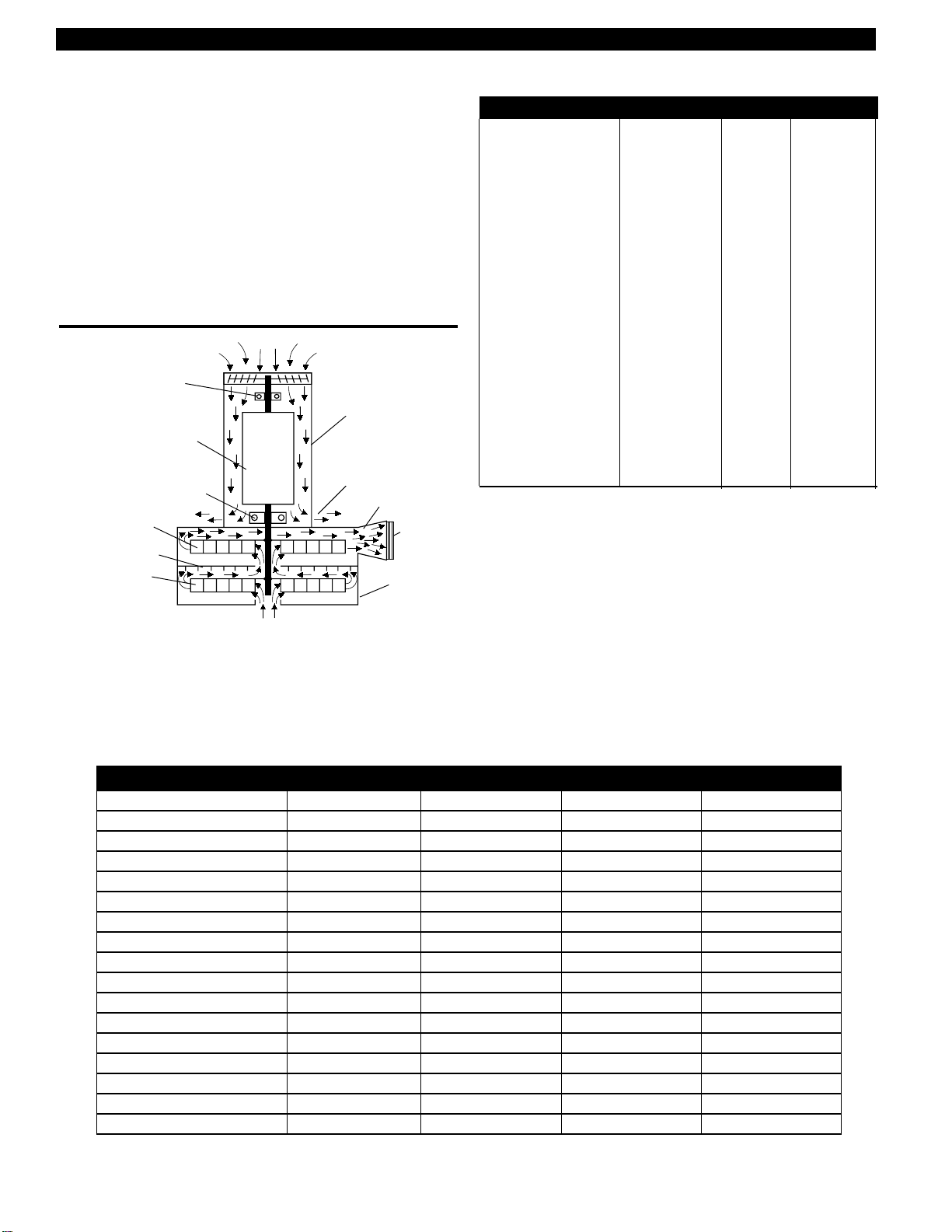
Lemmer Air Turbines use a universal motor. This type of motor must not be used in an area contaminated by volatile or
flammable materials since sparking can be expected in the normal operation of the motor and may ignite the contami-
nants causing a DANGEROUS EXPLOSION.
When a flammable liquid is sprayed, the turbine must be placed at least 20 feet away from areas where hazardous
concentrations of flammable vapors are likely to occur.
Use additional air hose if necessary to insure that the turbine is operated in a CLEAN, DRY, WELL VENTILATED
AREA.
NEVER PLACE THE TURBINE INSIDE THE SPRAY BOOTH!!
TABLE OF CONTENTS
SAFETY PRECAUTIONS .............................................................................2
SPECIAL SAFETY PRECAUTIONS ............................................................3
INTRODUCTION...........................................................................................4
PRODUCT SPECIFICATIONS......................................................................4
COATING APPLICATIONS ...........................................................................4
LEMMER TURBINE TECHNICAL FEATURES .............................................4
PREPARE FOR OPERATION
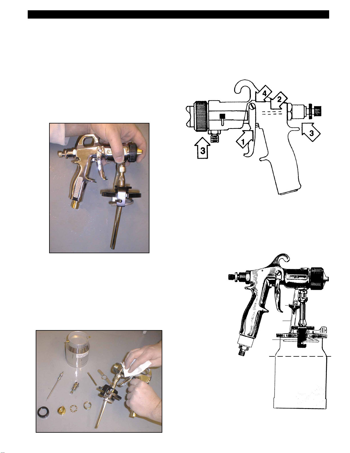
SPRAY GUN CONTROLS...............................................................5
POWER SUPPLY, MOTOR CARE...................................................6
FILTER MAINTENANCE .................................................................6
PAINT STRAINING AND THINNING ...............................................6
SELECTING THE PROPER FLUID SET ......................................................7
VARIABLE SPEED CONTROL ON T-75Q & T-90Q ......................................7
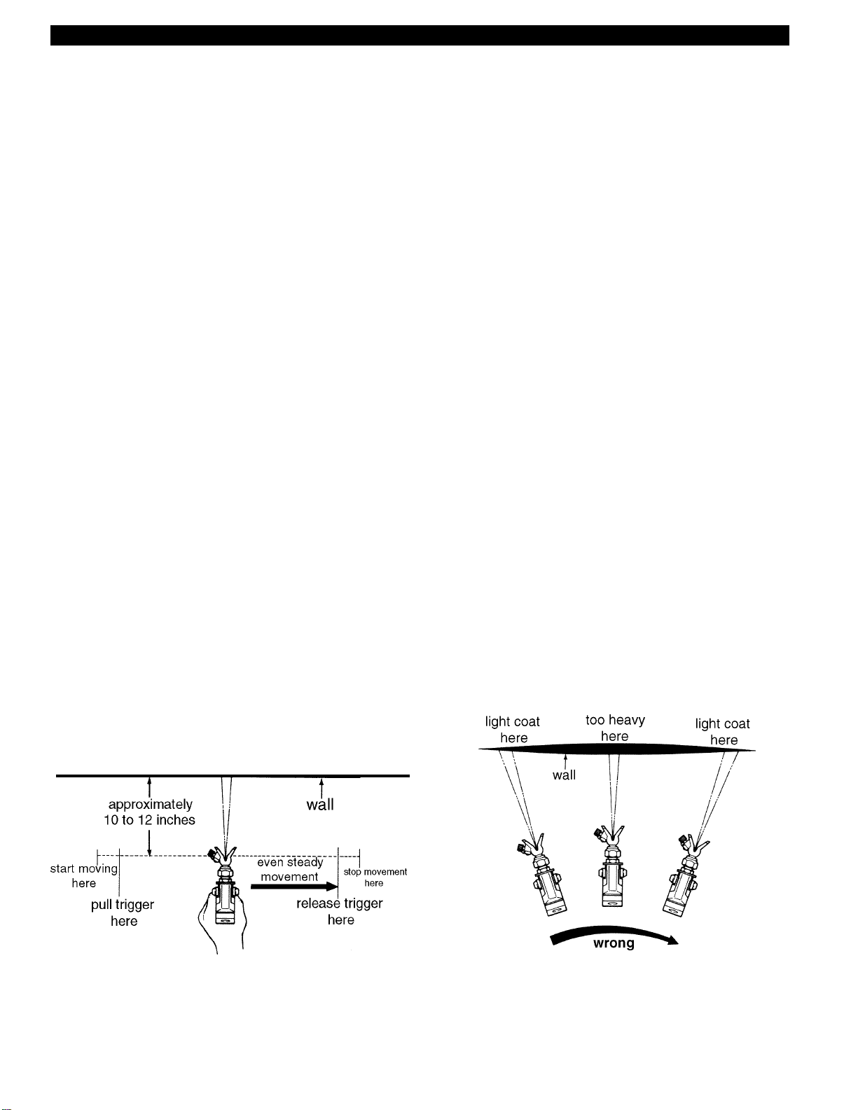
TIPS & TECHNIQUES FOR TURBINE SPRAYING ......................................8
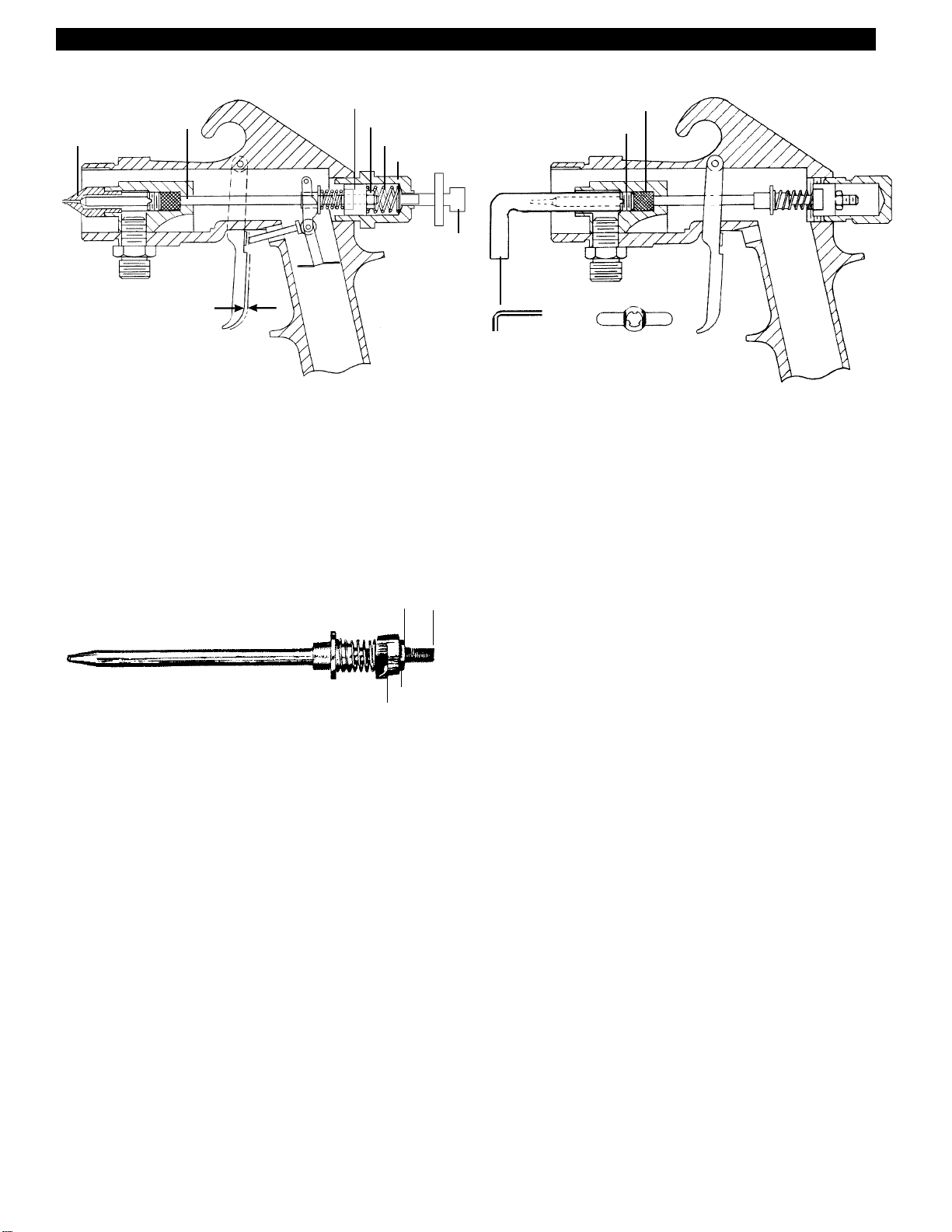
CLEANING, MAINTENANCE & SERVICE........................................... 9 & 10
SPRAYING WITH A PRESSURE FEED SYSTEM .....................................11
OTHER LEMMER PRODUCTS &TURBINE ACCESSORIES .......... 12 & 13
TROUBLESHOOTING ....................................................................... 14 & 15
HOSE CONNECTION DIAGRAM & AIR ACCESSORIES..........................16
PRESSURE POT PARTS LIST ...................................................................17
SERIES 700 HVLP GUN PARTS LIST & DIAGRAM ......................... 18 & 19
A728 HVLP GUN PARTS LIST & DIAGRAM ..............................................20
T-55Q/T-75Q PARTS LIST & DIAGRAM......................................................21
T-90Q PARTS LIST & DIAGRAM ................................................................22
MINI COMPRESSOR & TURBINE CART PARTS LIST & DIAGRAM.........23
DISTRIBUTION CENTRES ACROSS CANADA.........................................24
LEMMER PAINT SPRAYING EQUIPMENT LIMITED WARRANTY ...........24
SAFETY PRECAUTIONS

3
SPECIAL SAFETY PRECAUTIONS
CONNECTING PORTABLE TURBINES TO POWER SOURCE
WARNING
THIS EQUIPMENT MUST BE PROPERLY GROUNDED WHILE IN USE, TO PROTECT THE OPERATOR FROM
ELECTRICAL SHOCK. In the event of a malfunction, or breakdown, grounding provides a path of least resist-
ance for electric current to reduce the risk of electric shock. This unit is equipped with an electric cord having an
equipment-grounding conductor and grounding plug. The plug must be plugged into a matching outlet that is properly
installed and grounded in accordance with all local codes and ordinances.
DO NOT MODIFY THE PLUG PROVIDED - IF IT WILL NOT FIT THE OUTLET, HAVE THE PROPER
OUTLET INSTALLED BY A QUALIFIED ELECTRICIAN.
WARNING
The following safety hazards may occur during the normal use of this equipment. Follow these precautions.
Danger Area Hazard Precaution
Fire Hazard Solvents and coatings can be Spray area must be well ventilated
highly flammable, especially and appropriate safety precautions
- Spray Area - when sprayed must be followed especially as
provided by paint/material manufacturer.
Toxic vapors and spray mist hazard Certain materials may be harmful or Follow all requirements of the
fatal if inhaled, absorbed through Material Safety Data sheet supplied
the skin, or cause irreversible eye by your coating material manufacturer.
- Spray Area - damage Special attention to the type of body,
eye, and respiratory safety equipment
required for the material being sprayed .
Explosion Hazard Halogenated hydrocarbon solvents, Check with your local supplier or
i.e. methylene chloride, and 1-1-1 tri- Lemmer for the availability of stainless
chlorethane are not chemically steel nozzle holder order # L080-664
- Incompatible materials - compatible with aluminum or gal- and stainless steel 1 qt. cup.
vanized coated parts in your Lemmer
Spray System.
Inadvertant discharge of material Lemmer Turbine Spray Gun Cups are Be sure air is turned off, or air line
from spray gun cup. operated under continuous pressure. is removed before attempting to
remove spray gun cup.
Cord Motor Amperage Rating
Length 0-5 67891011121314151617181920
25 ft 18 18 18 18 18 18 16 16 16 14 14 14 14 14 12 12
50 ft 18 18 18 18 18 18 16 16 16 14 14 14 14 14 12 12
75 ft 18 18 18 18 18 18 16 16 16 14 14 14 14 14 12 12
100 ft 18 18 18 16 16 16 16 16 14 14 14 14 14 14 12 12
125 ft 18 18 16 16 16 14 14 14 14 14 14 12 12 12 12 12
150 ft 18 16 16 16 14 14 14 14 14 12 12 12 12 12 12 12

4
INTRODUCTION
CONGRATULATIONS
on choosing a new Lemmer
Portable Spray System! Your Lemmer Spray System is
exceptionally rugged in construction and designed to
operate with the best possible delivery efficiency. Like
any fine precision tool, its most efficient operation de-
pends on a thorough knowledge of its operation capabili-
ties and maintenance. With proper material preparation
and maintenance, your Lemmer will produce beautiful,
uniform finishing results for years to come.
Lemmer Turbine Operating Principle (2 stage)
Turbine.
Air outlet
fitting (to
gun).
Main motor bearing.
Turbine air in.
2nd stage rotor.
1st stage stator.
1st stage rotor.
Cooling air in.
Upper motor bearing.
Rotor.
Motor.
Cooling air out.
Air collector.
PRODUCT SPECIFICATIONS
COATING APPLICATIONS
COATING EXCELLENT GOOD NOT REC.
Multi-colour X
Stain X
Sealers (concrete) X
Asphalt Coating X
Primer X
Elastomerics X
Varnish X
Lacquer X
Sealers (wood) X
Acrylic X
Textured X
Block Filler X
Ext. Latex X*
Ext. Oil Base X*
Latex (Int.) X*
Enamel (alkyd) X*
*Some thinning may be required. Follow manufacturer’s
recommendations.
LEMMER TURBINE TECHNICAL FEATURES:
• Turbine life is almost solely dependant on air quality.
Any dust in the intake air will wear the turbine. The
Lemmer T-series all use a unique large area fine filter for
trouble-free service!
• The Lemmer T-55 turbine is a 2 stage, small diameter,
low rpm, and low operating temperature. The T-75 turbine
is a 3 stage, small diameter, higher rpm with variable
motor speed. The T-90Q is a 4 stage turbine with several
fixed speeds and patent pending motor control
technology to minimize heat and noise.
Specification T-55Q T-75Q T-90Q Turbine Cart
Amps @ 120 V 8 10.5 12 1.0
Circuit breaker std. std. std. (thermal-internal)
Number of air outlets 1111
PSI - sealed 4 6 8 60
PSI - spraying 2 3 6 30
Turbine blades (stages) 2 3 4 -
Turbine diameter 5.7 5.7 5.7 -
Heavy duty filtration std. std. std. -
Standard turbine hose 25' x 3/4" 25' x 3/4" 25' x 3/4" -
Maximum turbine hose 25' 50' 75' -
Material hose - - - max 50 ft
Cabinet Small - carry Small - carry Small - carry -
1 quart HVLP gun std. std. std. -
Air compressor - - - H.D. MC-80
Shipping size (inch) 15x15x16.5 15x15x16.5 15x15x16.5 26.5x29x33
Turbine weight (lbs) 19 21 21 33
Shipping weight (lbs) 29 34 34 41

5
SPRAY GUN CONTROLS
Figure 1a - Gun controls, A700 series.
Figure 1b. - Gun controls, A728 non-bleeder
Material Volume Control Knob
Controls how far the trigger can be pulled back. Turn out
for more material flow, turn in for less.
Air flow control valve.
Air Control Valve (on end of Turbine hose)
Controls both atomizing air and pressure in the one quart
cup. Control overspray mist by using only as much air as
is necessary for the material being sprayed. The lighter
the material, the less air needed. For T75Q and T-90Q
machines, select a motor speed first, then use the air flow
control valve to “fine tune” the spray if needed.
PREPARE FOR OPERATION
Figure 3. - Spray pattern control (turn air cap).
Spray pattern shape is determined by the 3 different
positions of the aircap on A700 guns. The aircap can be
rotated to make the pattern vertical, horizontal or in-
between on the A-728.
NOTE: The aircap adjusting ring on A-700 does NOT
have to be loosened to change patterns unless the air
cap is set to its widest pattern. Slight loosening may be
required to turn aircap on A-728.
Adjusting Spray Fan Width, A-700 Series.
Figure 4. - Spray fan width control (turn ring).
Spray fan size is determined by turning the control ring in
(for wide) or out (for narrow) for A700 series guns.
Adjusting Spray Fan Width, A-728
Use the fan control knob at rear of gun to adjust spray
pattern width. Turn the knob clockwise to decrease the
fan size, counter clockwise to increase it.
Note-all models: Smoother finishes can be obtained by
using a narrow pattern. More material output can be
gained by using a wide pattern.
Full flow
(clockwise)
wider spray fan
& more material.
normal sprayfan.
(start here)
narrow spray fan
& less material.
turn ring until air
cap is flush with
fluid nozzle end.
turn ring in.
turn ring out.
(if turned too
far gun will
stop spraying).
Round jet Horizontal Fan Vertical Fan
Fan width
control knob
Material
volume
control
knob.
Spray
pattern
control
air cap.
to air control
valve on end
of air hose.
To air control
valve on end
of air hose.
Fan width
control ring.
Spray
pattern
control
air cap.
Material
volume
control
knob.

6
PREPARE FOR OPERATION
PAINT STRAINING AND THINNING
The surface to be sprayed should be completely clean
and dry to achieve proper adhesion.
Always strain all material to be sprayed. This includes
color, reducer and hardners if used.
Figure 8. - Automotive paint reduction.
Paint Reduction - Automotive Type Finishes. Reduce
and catalyze all paint to manufacturer’s specifications.
Remember: To compensate for the faster drying time of
turbine systems, use a reducer one step slower than for
conventionalair spray to enhance flow-out.
Figure 9. - Industrial paint reduction.
Paint Reduction- Industrial or domestic coatings (if
no reductions are given.) Thoroughly mix material to be
sprayed, and gradually mix in the proper reducer until
proper spraying consistency is reached. To test: withdraw
stir stick from the thinned paint. As soon as the paint
stream running off the stir stick breaks into droplets, the
first few drops should be about one second apart.
Figure 10. - Test Spray Pattern.
Test Spray Pattern.
Spray material on a test surface to check for proper
material flow, coverage and atomization .
1. Open air valve to full flow.
2. Adjust aircap from neutral position to required pattern
size.
3. Adjust material control knob for proper flow.
Thin Materials: Decrease air flow through gun to mini-
mize mist.
Heavy Materials: If flow rate is too slow, additional
thinning will be needed or a larger fluid nozzle will be
required, see Page 8.
POWER SUPPLY, MOTOR CARE
All Lemmer Portable Turbine Systems are lifetime lubri-
cated. The only maintenance required is scheduled filter
cleaning and replacement.
FILTER MAINTENANCE
The filter must be clean at all times. This is very important
to the life of your turbine. We recommend that the filter be
checked weekly.
—Clean main filter by one of these methods—
Warning: Never put damp filters in the turbine!
Figure 5. - Cleaning filter by tapping.
Tap gently on flat surface dirty side down.
Figure 6. - Cleaning filter with air.
Direct compressed air (100 P.S.I. max.) thru panel oppo-
site the direction of arrows.
Figure 7. - Cleaning filter with water.
1. Soak 15 min, in water and a mild detergent.
2. Rinse until clean.
3. Air dry - do not use compressed air.

7
SELECTING THE PROPER FLUID SET
The Lemmer series 700 spray gun comes with the 1.4 mm nozzle set which is desired for most industrial finish applica-
tions. However, other combinations may be required for very fine finish work, or when spraying heavier materials.
Fluid set selection
Nozzle sets range in size to provide different fluid flow rates. For low flow rates or light viscosity fluid, select the smaller
nozzle sizes. For high flow rates or high viscosity fluid, select the larger nozzle sizes. For the best atomization, use the
fluid nozzle that will give the required flow with the needle fully triggered.
Measuring paint viscosity
1. Thin paint according to paint can instructions. Be certain to use a thinner which is compatible with paint used. If
no thinning instructions are given, a general rule of thumb is 5 to 15% thinners. (fine finish up to 35%)
2. Stir paint completely and strain.
3. Use the viscosity cup to measure paint as follows:
a) Submerge the Lemmer Viscosity cup in the paint.
b) Lift the cup out of the paint and begin timing.
c) Stop timing when the steady paint stream is first broken.
d) The time recorded is the paint’s viscosity.
4. Now read the nozzle chart and choose the nozzle which lists the viscosity range (under "type of material") your
material falls into.
Note: This nozzle chart has been made as accurately as possible. Not all paints will exactly comply due to paint
ingredient variations. However, it is an excellent starting point for learning the basics spray painting.
NOZZLE SIZING - HVLP 700 (VENTURI & TURBINE)
There are 4 basic sizes of fluid nozzles available:
Material being sprayed .......................................................... nozzle size ......................... air cap.... viscosity
Fine finish work with stains, lacquers, urethanes, enamels, .... 1.0 mm diameter (.051") .... "S 1" ....... 16 - 22 sec. (thin)
automotive base/clear coats.
Normal output with lacquer & enamels, urethanes, varnish,.... 1.4 mm diameter (.059") ...."S 1" ....... 19 - 32 sec. (medium)
zinc chromate, automotive primers.(also thinned latex & oil base).
Heavy output with lacquer & enamels, butyrate & nitrate dope 2.0 mm diameter (.079") .... "S 20" ..... 26 - 38 sec. (medium)
and epoxies. Latex and oil wall paints.
Wax base stripper, sound deadeners, multi-colors, ................. 2.8 mm diameter (.110") ...."20"......... 38 + sec. (heavy)
latex paint.
NOZZLE SIZING - A-728 HVLP NON-BLEEDER
There are 5 sizes of fluid nozzles available:
Material being sprayed .......................................................... nozzle size ......................... air cap.... viscosity
Fine finish work with stains, lacquers,...................................... 1.0 mm diameter (.039") .... "1.0"........ 16 - 22 sec. (thin)
enamels, automotive base/clear coats.
Medium speed with with lacquer & enamels, ........................... 1.3 mm diameter (.051") ...."1.3"........ 18 - 30 sec. (medium)
urethanes, clear coats
Normal output with lacquer & enamels .................................... 1.5 mm diameter (.059") .... "1.5" ........ 20 - 35 sec. (medium)
urethane, varnish, automotive primers..................................... (standard with A728)
Higher output with primers and industrial finishes ................... 1.8 mm diameter (.071") .... “1.8" ........ 25 -38 sec. (heavy)
Thin to medium body waterbase products
Latex and oil paint, multi-colors ............................................... 2.0 mm diameter (.079") .... "2.0" ........ 38 + sec. (heavy)
For ordering details see parts list in back of manual. Note: nozzle and needle must be same size, eg: a 1.4 mm
needle will not work with a 2.0 nozzle. Aircaps and nozzle/needle sets must also be matched for correct operation.
VARIABLE SPEED CONTROL ON T-75Q AND T-90Q
VARIABLE SPEED CONTROL
The T-75Q and T-90Q are equipped with a variable
speed motor control which gives the user a wide range of
adjustment over atomization, heat and noise. An
additional, patent pending feature of the T-90Q will
automatically slow the motor when spraying stops to
reduce heat and increase motor life.
INITIAL SPEED SETTING
An excellent starting point is speed 2 on the T-75Q, or
speed 3 on the T-90Q. These speeds are typically used
with medium viscosity materials which are sprayed with
nozzles of 1.3 to 1.8 mm.
NOTE: When first selecting a motor speed, always
ensure the airflow control valve on the hose is fully open
to prevent interference between these two controls.
ADJUSTING THE SPEED
Thicker paints and/or nozzles larger than standard size
(1.4 & 1.5mm) often need more power for correct
atomization. For these situations, use a higher speed
setting.
For thinner paints, smaller nozzles and/or finer work,
excess air pressure may cause unwanted overspray. For
these situations use a lower speed. A lower speed setting
will also reduce air temperature from the turbine, which is
important if the material tends to dry very quickly.

8
SPRAY TIPS FOR TURBINE SPRAYING
Figure 15. - Proper way to trigger spray gun. Figure 16. - Result of flexing wrist while spraying.
Get professional looking results by following the spray
tips below.
1. Turn Turbine on a few minutes before spraying, to
allow air to warm up.
2. Adjust air control valve for the minimum air required
to atomize the fluid properly. (optional on the T-55).
3. Keep the gun perpendicular to the surface. Always
hold the gun perpendicular to the surface with the tip
approximately 6 to 8" from the surface. If held at an
angle (up and down or side to side) paint will build up
unevenly and leave the work splotchy. (See figure
16). This also saves material and reduces mist.
4. Move with a smooth arm stroke Move the gun at a
steady even pace while keeping the gun perpendicu-
lar to the surface. (See figure 15) Do not move the
gun by flexing your wrist. Fanning the gun will cause
excessive overspray and uneven coverage. (See
figure 16). If the rate of speed is not comfortable for
you, select another nozzle/needle size according to
charts on page 8.
5. Start moving the gun before triggering To get
smooth overlap and prevent initial paint buildup, start
your stroke movement before pulling the trigger. At
the end of the stroke release the trigger before
stopping.
NOTE: For a nice even finish, always overlap previ-
ous strokes by the same amount, generally 50%. Put
on a full wet coat whenever possible.
PROPER SPRAYING TECHNIQUES
Warning: Keep the Turbine away from the spray area.
Turbine filter must be clean to provide motor cooling
and atomizing air.
1. When using a turbine spray system, use slower
reducer or thinner to compensate for the faster drying
time due to the warm air of the turbine. DO NOT
OVER REDUCE. Hold the spray gun closer and a
slower drying reducer to enhance paint flow out.
2. To avoid runs and snags, remember this unit applies
more paint per pass than a conventional spray gun.
Take a minute to experiment on a discarded panel.
3. Be sure to turn turbine on a few minutes before
spraying for warm up time. Be sure to turn turbine off
when not in use, they do not shut off automatically.
4. When blending spots, work from the outside in. Start
one inch out, no dusting. This eliminates “chronic
halo” .
5. We recommend using two lengths of 25 foot hose
when applying automotive finish coats. The additional
hose will cool the air for better “flow out”.
6. Be sure to use the proper flluid nozzle, needle and
air cap for the material you are spraying, see page 8.
The use of a smaller aircap than fluid nozzle will
produce a smoother finish.
7. When material is first being applied, have the fluid
nozzle and aircap in the "normal spray pattern"
position as shown on previous page, then make
adjustments from there to control fan and atomiza-
tion.

9
CLEANING INSTRUCTIONS
As with any spray equipment, your sprayer must be
cleaned properly or it will not operate properly. If
followed, the following guidelines will insure trouble
free performance from your sprayer.
CAUTION: Clean with water if latex is used. Clean
with paint thinners for oil based paints. Both water
and paint thinner will be refered to as "solvent" from
here on in.
1. Back flush gun. Remove material cup and hold gun
over a shop cloth. Connect air supply, hold finger
over air cap, and pull the trigger.This will force all the
air through the gun down the air pressure tubes,
blowing out any excess paint that may have been
trapped.
Figure 17. - Back flushing gun.
2. Solvent flush gun. Empty material from cup and add
about 1" clean solvent. Attach cup to gun and swirl it
around while spraying.
Remove cup and pull trigger to break air lock in
material tube. Empty balance of solvent from cup and
repeat process with clean solvent.
Remove cup and wipe clean. Clean gun body with a
solvent dampened cloth.
Clean needle, fluid nozzle and air cap with solvent
and brush.
Figure 18. - Solvent flushing gun.
3. Lube instructions. To keep the gun in proper work-
ing order be sure to check and lubricate each num-
bered item in diagram using silicone-free spray gun
lube or vaseline.
1. Lube the Trigger Axle
2. Lube the Needle - full length
3. Lube all threaded areas
4. Lube Trigger Pivot as needed
Figure 19. - Lubricating gun.
NOTE: We recommend running light oil or mineral
spirits through the unit before storing. When using
latex paints, make sure the unit has been completely
cleaned before storing with mineral spirits. Mineral
spirits react with latex paint to form a jelly-like sub-
stance.
Note: Back flush-
ing is very impor-
tant in keeping
valve (1), hose (2),
and tube (3) clean.
Any blockage here
prevents pressuri-
zation. To help
prevent paint from
entering tube (3),
refrain from over-
filling the con-
tainer or tipping
the spray gun at
extreme angles.
Warning: Paint cup is under
continuous pressure, even after
air line has been disconnected.
Do Not pull trigger after spray-
ing! Release pressure with the
cup locking lever immediatly
after use. Wear eye protection!
2
1
3
HVLP Venturi
gun.
maximum fill

10
MAINTENANCE & SERVICE
DISASSEMBLY, A700 SERIES:
1. Remove air cap, detent plate, spring; spring cap,
spring, & needle. Lastly remove nozzle using nozzle
tool.
ASSEMBLY, A700 SERIES:
2. Pre-adjust needle as shown in diagram and tighten
nut. Lubricate with vaseline and install with spring, and
spring cap (loosely).
3. Adjust packings by turning the packing wrench
clockwise and triggering the needle while you
tighten.
When the needle binds, back off until the needle just
moves freely.
4. Install nozzle, spring, detent plate, and air cap.
5. Check trigger free travel.
Important: Ensure that the
fluid adjusting screw is backed out all the way.
If adjustment is required continue to step 6.
Turbine gun.....1/16" spring travel (before needle moves)
Venturi gun.....3/8" spring travel (before needle moves)
6. Adjust trigger by removing the spring cap, loosening
the lock nut and turning the drum until correct free
travel is achieved. Adjusting less than 3/8" decreases
trigger free play. Tighten lock nut and install spring with
cap.
If tool kit is required
, use order #L080-650 for 1 x
packing wrench, 1 x nozzle tool, and 1 x cleaning brush.
DISASSEMBLY, A728:
1. Remove air cap ring and aircap. Next remove material
flow adjusting knob and spring from rear of gun, then
grasp needle and remove. Lastly remove nozzle using
nozzle tool or 13mm wrench.
ASSEMBLY, A728:
1. Lightly lubricate needle with vaseline and insert
through rear of gun. A728 needles require no
adjustment.
2.Install fluid nozzle and tighten 5-7 ft lb with nozzle
tool or 13mm wrench. Note: Ensure nozzle size
matches the needle in gun.
3. Reinstall spring and material flow control knob.
4. Install aircap, then install and tighten aircap ring.
5. Packing adjustment, if required, can be made by
turning the 8mm hex nut just in front of the trigger. In
the case of fluid leaking around the needle where it
enters the packing nut, just tighten the nut slightly until
the leakage stops. If the nut is overtightened, the
needle will bind. Loosen the nut slightly until the needle
moves without binding.
nozzle
1/16" spring travel, turbine
3/8" spring travel, venturi
needle adjustment drum
spring
lock nut
adjusting
screw
spring cap
Nozzle Tool
Packing
wrench
needle packing
packing nut
Figure 21. - Needle packing adjustment (A700)
Figure 20. - Trigger adjustment (A700)
3/8"
nut
drum
Note: nozzle & needle must be the
same size, eg: a 1.6 needle will not
work with a 1.8mm nozzle.

11
SPRAYING WITH A PRESSURE FEED SYSTEM
WARNING: NEVER AIM SPRAY GUN AT ANY PART
OF THE BODY. EVEN WHEN TURBINE IS OFF, THE
SPRAY GUN WILL RETAIN FLUID PRESSURE.
IMPORTANT: BEFORE TURNING ON AIR PRESSURE,
TURN OUT THE REGULATOR ADJUSTING KNOB ALL
THE WAY COUNTER CLOCKWISE TO SHUT OFF AIR
PRESSURE. TURN ON THE AIR AND THEN ADJUST
THE REGULATOR TO THE REQUIRED PRESSURE.
Pressure feed spraying operates basically the same
whether using the 2 quart remote, or the 2-1/2 gallon
paint tank. The main advantages of pressure feed are:
1. The spray gun can operate in any position, and fit in
smaller areas.
2. The weight of the material is off the spray gun for less
operator fatique.
3. A wider range of viscosities may be used with the
same fluid nozzle.
4. Generally can increase application rates and reduce
paint mist.
5. Saves time by requiring less fills.
OPERATION: Reduce material as recommended by
manufacturer, strain, and fill container no more than 3/4
full. Leave turbine turned off, and turn compressor on.
Turn regulator knob clockwise until two quart reads 2 to 4
P.S.I., on the 2-1/2 gallon tank to read 4 to 8 P.S.I.
(Heavier material or longer material hose length will
require more pressure.)
Pull trigger of spray gun fully, the material stream should
travel 12" to 18" in a downward arch. Increase or de-
crease the regulator pressure as necessary to obtain
proper material flow.
Turn turbine on and adjust the spray pattern with the
pattern control ring. It is best to control the gun speed
with the regulator by increasing or decreasing regulator
pressure rather than with the trigger.
BE CAREFUL NOT TO OVERPOWER THE ABILITY OF
THE GUN TO ATOMIZE PROPERLY BY USING TOO
MUCH FLUID PRESSURE.
WARNING: Never attempt to loosen or remove the cover
before fully releasing the air pressure. Turn air compres-
sor off, and pull lift ring on relief valve, or turn out pres-
sure release screw until pressure is completely released.
TROUBLE SHOOTING:
CONTAINER FAILS TO PRESSURIZE:
Be sure the bleeder hole on the underside of the paint
tank lid under the regulator is clean. On the two quart, be
sure the check valve underneath the lid below the regula-
tor is free and clean.
INTERMITTENT SPRAY PATTERN:
Check the gasket on the container for leaking.
CONTAINER PRESSURIZES BUT NO MATERIAL
FLOW:
Release pressure, check fluid nozzle for blockage.
Remove material hose and blow out with compressed air.
TWO QUART CUP
When spraying is finished, turn off both the compressor
and turbine. Release the pressure in the cup with the
pressure release screw. Elevate the spray gun and pull
the trigger, this will allow the material in the fluid hose to
drain back into the cup.
Flush out with the appropriate solvent using compressor
air only. Be sure to always release pressure on two quart
before unscrewing the lid. A light coat of vasoline on the
cup threads is recommended.
CAUTION: If the cup is accidentally tipped over or held
at too great an angle, fluid might leak into the regulator.
In the event this happens, clean immediately.

12
OTHER QUALITY LEMMER PRODUCTS
LEMMER'S Full line of equipment comes with FIRST CLASS SERVICE in numerous
locations across CANADA, and a FULL ONE YEAR WARRANTY. For information on choosing the
right sprayer for your job, please contact your nearest LEMMER outlet.
AIR GUNS & PRESSURE POTS
Conventional air spray guns for fine
finishing. Suitable for countless industrial
and automotive applications. Available in
suction, gravity, and pressure feed
versions. Each is available in many
different needle sizes.
LINEMARKERS
Designed to handle the abrasive nature
of road marking paint. Units range from
small single gun electric models to larger
gas powered walk-behinds. The larger
units are available in compact diaphragm
design or rugged piston pump style.
HVLP TURBINE & VENTURI UNITS
High Volume Low Pressure sprayers are
used for fine finishing where overspray
must be kept to a minimum. The finish
results are equal to or better than
conventional air spray. The turbine
systems are self contained and do not
require an outside air source. The
VENTURI spray gun only uses about 8
CFM of shop air. Applications vary from
automotive finishing to commercial multi-
color architectural coating.
ELECTROSTATIC UNITS
The electrostatic WRAP-A-ROUND
charge makes this the best method of
spraying metal with next to no overspray.
Solvent and waterborne versions are
available. The conversion kit will hook up
to most airless pumps and we carry a
completely self contained portable
system.
AUTOMATIC GUNS
Suitable for all heavy duty airless applica-
tions. Air actuated, universal rod mount-
ing, and standard 1/4" NPS hose connec-
tion.
ELECTRIC DIAPHRAGM
These sprayers are the same as above
piston pumps except in a lower cost
diaphragm design. The motor runs
continuous for the ultimate spraying
pressure control. Hopper models are
easiest to clean.
ELECTRIC PISTON PUMPS
Commercial airless sprayers for all sizes
of jobs and spraying a large variety of
paint types. These units are portable and
come in many different performance
categories. There are small units for
spraying a house or barn once a year,
and large units for spraying warehouses
on a continuous basis.
PAINTING SUNDRIES
Strainer bags, filters, pressure rollers etc.
A large variety of painting accessories to
help make a cleaner and more efficient
working environment.
AIRLESS ACCESSORIES
A very large assortment of hoses, guns,
tips, and filters, etc. These items are
universal to most airless spray equipment
on the market.
PNEUMATIC PISTON PUMPS
Being an air powered airless, these units
are generally used for industrial coatings.
Applications range from portable lacquer-
ing to plumbed-in automatic systems.
Also excellent for industry where operat-
ing conditions are very demanding.
TRANSFER PUMP
It can be used to transfer paint to remote
locations, or directly to high pressure
pumps. At a 1:1 ratio with up to 125 PSI
air pressure it can also supply numerous
air guns.
Nov09
GAS POWERED AIRLESS
These units are ready for the biggest
outdoor jobs. Robust piston pump design
for long life and maximum performance.
RUSTPROOFING EQUIPMENT
Lemmer carries a wide range of pumps,
spray guns and accessories for the
automotive rustproofing industry.

13
ACCESSORIES FOR TURBINES AND HVLP GUNS
Suction strainers
Slip on strainers for cup gun or 2 litre pot,
eliminates surface blemishes and plugged tips.
100 mesh strainer (small) ...............L015-849
100 mesh strainer (small, pkg/5)..... L015-860
100 mesh old metal L080-587 strainer is NLA.
Gun kit for A700
Have it when you need it:
1 - Blue compartmented parts box.
1 - 1.0mm Fine Finish fluid nozzle assembly.
1 - 2.0mm Latex fluid nozzle assembly.
3 - L080-548 Air pressure tubes.
5 - L080-581 Cup gaskets.
1 - L080-587 Strainer.
+ - Room for your gun cleaning kit.
........................................................L080-689
Turbine whip hose, 1/2"id
Very flexible smaller diameter hose with male-
female fittings.
1/2"I.D. x 60" ...................................L080-703
Turbine Hose, 3/4"id (replacement)
Turbine Air Hose, female fittings both ends.
3/4"I.D. x 25'.................................... L080-605
Additional female quick disconnect coupler
and air valve for second spray gun:
Quick ccoupler (WHF).....................L080-554
Air control valve ..............................L080-549
Turbine cart kit
Increase the versatility and output of your T55,
T75 or T90 turbine. Built-in mini compressor
pressurizes the pot for faster material delivery.
Pot and turbine not included.
Turbine cart kit ................................ L080-100
Paint hose
Lined material hose comes complete with
fittings.
25' ...................................................L080-644
50' ...................................................L035-103
Paint hose connector
3/8"male ..........................................L035-502
2 1/4 Gallon paint tank
Galvanized tank with inner teflon coating and
replaceable plastic liner. Works with any
Lemmer HVLP or air spray gun with an
existing suction pot (bottom feed). Pressure
feeding gun can improve delivery efficiency
and gun speed, recommended when spraying
glue. Comes complete with dual regulators
and gauges, order material hose separately.
Requires compressed air source.
Paint tank ........................................L011-075
Replacement gasket ....................... L011-156
Vented"Y" connector
Use when connecting A728 non bleeder gun to
T-55 and T-75 turbines. Prevents excess
pressure and overheating of motor.
Vented Y Connector........................L080-649
Cleaning brush kit
This kit contains many handy brushes and
broaches to clean all areas of a spray gun.
Air gun brush kit ..............................L015-606
Viscosity cup
Takes the guess work out of reducing your
material. ..........................................L034-191
Spray hoods
Spray hoods (pack of 3) ..................L034-205
Respirator
North respirator (complete) .............L034-200
Strainer bags
1 Gallon strainer w/elastic...............L034-208
5 Gallon strainer w/elastic...............L034-209

14
TROUBLESHOOTING
Provided you have followed the instructions, the sprayer will operate efficiently and give trouble-free service. Should
any unexpected problem arise you can, in most cases, remedy the problem by following the chart below. If you find
that you cannot correct the problem, then take the sprayer to your nearest Lemmer outlet. Many of the “causes” listed
are unlikely to happen. However, all are included in an attempt to cover every possibility.
IT IS ABSOLUTELY ESSENTIAL FOR TROUBLE-FREE OPERATION THAT YOUR SPRAY GUN BE KEPT CLEAN
AND FREE OF RESIDUAL PAINT BUILD-UP ON THE INTERNAL PARTS. IT MUST BE CLEANED AFTER EVERY
USE.
Cause
The 710 Spray Gun requires pressure
in the paint cup to force the material
being sprayed up the fluid tube and
out the fluid nozzle. Any blockage
restricting free material flow, or loss of
air pressure in the cup, will greatly
effect gun performance.
Needle not seating in fluid nozzle.
Air passages blocked in air cap, fluid
nozzle partially plugged.
Remedy
1) Check fluid nozzle and fluid tube for dried
paint blocking passages, for tightness, being
bent or damaged. If blocked, clean with
brushes provided after soaking in solvent.
2) To check air pressure to cup, back flush
your gun. If air is not flowing freely from
lower air pressure tube, determine where
the blockage is and clean by soaking in
solvent and blowing out with air.
3) If air is flowing freely in step 2, check for
positive seal of cup gasket. Do this by
adding a couple of inches of solvent to cup,
tilt gun with air on, and rotate gun a full 360°
slowly. Any leaking at seal indicates a loss
of air pressure. Replace gasket.
4) Check needle packing adjustment. Any fluid
loss through packing will effect fluid pres-
sure, and will also cause a paint build up in
the gun body. The gun body may be soaked
in solvent and cleaned with the brushes
provided.
When soaking gun body keep
air control valve out of the solvent.
5) Check needle drum adjustment. Material
flow will be restricted if there is too much
free travel between the trigger and the
needle. (A700 series)
NOTE: Be sure that the proper set has been
selected for the material being sprayed.
6) Ensure the check valve on gun is not
blocked and is installed correctly. i.e.
tapered end points to container(A-728 only)
Check needle drum adjustment. Check for
loose fluid nozzle, bent nozzle or needle
See needle packing adjustment. If packing is
set too tight, needle will not restore after
trigger is released. Replace if nozzle or
needle is worn.
NOTE: nozzle & needle must be the same size,
eg: a 1.4 mm needle will not work with a 2.0
mm nozzle.
Remove and soak in solvent. Do not use
metal probes to clean orifices as this will
permanently damage them.
Problem
i NO OR SLOW
MATERIAL FLOW,
INTERMITTENT
SPRAY OR FLUT-
TERING PATTERN.
ii PAINT LEAK AT
FLUID NOZZLE
AFTER TRIGGER
HAS BEEN RE-
LEASED.
iii POOR SPRAY
PATTERN

15
Cause
The atomized paint droplets are not
flowing together to form a smooth,
level, uniform surface. This can be
caused by the following:
1) droplets too large
2) droplets drying too fast to flow out
3) cold weather spraying.
Condensation of moisture trapped in
the applied coating when spraying in
hot, humid conditions.
Silicone contamination from lubri-
cants, grease, polish of waxes on the
surface being sprayed.
Applying too much paint per pass for
the drying conditions.
Sprayed film surface drying before
solvent gas can be released.
Remedy
1) DROPLETS TOO LARGE - Be sure to
maintain proper gun distance, 4" to 8". See
air cap ad justment on. If droplets are still
too Iarge, reduce material or use a smaller
air cap. Be sure air intake filter on Turbine is
clean to allow full air flow. An air hose that is
too long will reduce atomizing air. Ensure
airflow contol valve fully open (all models) or
increase motor speed (T-75Q & T-90Q)
2) DROPLETS DRYING TOO FAST TO
FLOW OUT - Keep object being sprayed out
of direct sunlight. When spraying in warmer
temperatures use a slower evaporating
solvent or a retarder.
3) COLD WEATHER SPRAYING - Try to keep
material and object being sprayed as close
to room temperature as possible. When
sprayed on a cold surface most paints will
become too thick to flow out properly.
1) Allow turbine to warm up a few minutes
before spraying.
2) Store material off concrete floors at room
temperature.
3) Apply lighter
coats
and allow for proper dry
time.
4) Use a slower evaporating solvent or re-
tarder.
5) Do not spray in windy conditions.
Clean all parts with a cleaning sclvent. Use
one solvent rag and a clean wiping rag.
Change rags as required. If problem persists
use a fish eye eliminator.
1) Move gun faster or decrease material flow.
2) Maintain proper gun distance.
3) Reduce amount of thinner or use a faster
drying thinner.
1) Apply material in lighter coats to allow
proper evaporation.
2) Be sure to use recommended thinners.
3) Follow steps above in "droplets too large” to
increase atomization.
Problem
iV ORANGE PEEL -
PAINT SURFACE
NOT SMOOTH
V BLUSHING -
CLEAR COATINGS
APPEARING MILKY
Vi FISH EYES -
SMALL POOLS ON
PAINTED SUR-
FACE THAT WILL
NOT FILL.
Vii RUNS AND SAGS
Viii SOLVENT POPS
OR BUBBLES
TROUBLESHOOTING

16
HOSES & ACCESSORIES FOR AIR SPRAY EQUIPMENT
14
1
2
4
5
6
3
Gun air controlers
4
4
4
Pos. Part nos. Description Qty.Pos. Part nos. Description Qty.
1 L015-012 A-910 air gun with container
L015-020 A-928 HVLP gun with container
L080-506 HVLP venturi pressure feed gun
L080-504 HVLP venturi suction pot gun
2 L080-726 Fluid hose, 5' x 1/4"
L035-106 Fluid hose, 4' x 3/8" (MF extension)
L080-659 Fluid hose, 15' x 3/8"
L080-644 Fluid hose, 25' x 3/8"
L035-100 Fluid hose, 50' x 1/4"
L035-103 Fluid hose, 50' x 3/8"
L035-502 Hose connector, 3/8"
3 L035-116 Air hose, 5' x 1/4"
L035-117 Air hose, 15' x 1/4"
L035-121 Air hose, 25' x 1/4"
L035-119 Air hose, 50' x 1/4"
L035-501 Hose connector, 1/4"
2&3 L080-727 Twin line hose, 5' x 1/4
L080-728 Twin line hose, 15' x 1/4
L080-662 Twin line hose, 25' x 1/4
L080-729 Twin line hose, 25' x 3/8 (1/4 air)
L080-661 Twin line hose, 50' x 3/8 (1/4 air)
L080-725 Twin line hose, 50' x 1/4
4 L011-081 Air regulator complete, mini
L035-830 Ball valve, 1/4" FF
L011-550 Air flow control valve
5 L011-075 2 1/4 Gallon pressure pot (H.D.)
6 L035-121 Air hose, 25' x 1/4"
L035-122 Air hose, 50' x 3/8"
7 L080-501 HVLP turbine pressure feed gun
L080-500 HVLP turbine sution pot gun
8 L080-554 Turbine hose quick disconnect coupler
9 L080-605 Turbine hose, 25'
L080-554 Quick disconnect coupler (WH-F)
10 L035-410 Quick disconnect coupler (1/4" F, auto)
11 L035-413 Quick disconnect nipple (1/4" M, auto)
12 L035-412 Quick disconnect nipple (1/4" F, auto)
13 L035-501 Hose connector, 1/4
L035-502 Hose connector, 3/8
L036-223 Hose connector, 1/4F x 3/8M (swivel)
14 L080-683 Hose "Y" connector
15 L080-649 Air hose "Y" connector
16 L080-688 Blow gun nozzle
17 L080-549 Turbine air control valve
18 L080-551 Quick disconnect (WH-F)
19 L080-703 Turbine whip hose, 60"
20 L015-860 Suction strainer, new small 100 mesh(pkg/5)
21 L080-580 Container (without lid)(700 series only)
L080-648 Lid for container (with gasket) (700 series)
L080-582 Lid gaskets, pack of 5 (700 series only)
NOTE: HVLP guns must be pressure fed (either by fluid hose or by pressurized container);
• pressure feed A700 series needs L080-586 plug installed. A728 gun uses L081-365 plug.
• turbine and suction pot: A700 uses pressure tube only. A728 must use one way valve.
• suction pot version run from a compressor (A700 venturi version) must have a one way valve
installed. A928 uses mini regulator mounted at air inlet of gun to pressurize container.
7
2
9
6
5
8
Air connectors
10
11
12
13
15 16 17 18
19 20 21
Other accessories
Nov09
(eg. L080-100 turbine cart)

17
TURBINE PRESSURE POT PARTS LIST
2-1/4 gallon Pressure pot
(Heavy Duty 4 clamp)
Pos. Part nos. Description Qty.
L011-075 2 1/4 Gallon pressure pot
1 L011-155 Tank 1
2 L011-156 Cover seal 1
3 L011-157 Cover 1
4 L011-158 Safety valve, 50 psi 1
5 L011-159 Tee fitting with swivel 1
7a L035-510 Connector, 1/4"x1/8" 1
7b L035-661 Tee, 1/4"M 1
8 L011-178 Mini regulator, 0-60 psi, fluid 1
9 L011-192 Air guage, 0-60 psi, 1/8" bottom 1
10 L011-179 Mini regulator, 0-125 psi, air 1
11 L011-193 Air guage, 0-160 psi, 1/8" bottom 1
12 L036-070 Plug, 1/8"M 1
13 L011-164 Handle 1
14 L011-165 Handle lock nut 1
16 L011-167 Outlet elbow, 3/8"MM 1
17 L011-168 Wing nut 4
18 L011-169 Retaining arm 4
19 L011-170 Pin 4
20 L011-171 C-clip 8
21 L011-172 Material tube 1
22 L035-571 Elbow, 1/4"M 1
L035-561 Plug, 1/4" 1
23 L075-277 Decal, 7.5" Lemmer Logo 1
24 L011-173 Decal, pressure pot settings 1
25 L014-565 Decal, 50 psi max 1
26 L014-566 Decal, 100 psi max 1
Accessories:
L011-590 Pressure pot liner (formed) opt.
WARNING:
Make sure pins
are properly
fastened before
pressurizing
the tank!
1
4
5
7a
8
97b 10
11
12
13
14
CAUTION: Do
not use wrench
or pliers to
tighten knobs.
Hand tighten
only.
16
18
17
21
CAUTION: Make certain that
all pressures within the
system are relieved before
attempting to remove any
component or part of a com-
ponent.
WARNING: NEVER ALLOW
PRESSURE IN PAINT TANKS
TO EXCEED 50 LBS.
20
19
22
23
2
24
3
26
25
Nov09
Pos. Part nos. Description Qty.
L080-200 2 Qt remote pot, red regulator
1 L080-210 Handle 1
2 L080-211 Handle lock nut 1
3 L080-212 Outlet tee 1
4 L080-213 Connector, 2pc 1
5 L080-214 Air regulator complete (6-24) 1
6 L080-635 Safety valve, mini 1
10 L080-219 Regulator body 1
11 L080-220 Connector 3
12 L080-221 Guage 0-60 psi, btm 1/8, chrome 1
14 L080-222 Spring 1
15 L080-223 Valve 1
16 L080-224 Valve housing 1
17 L080-225 Diaphragm complete 1
20 L080-231 Spring 1
21 L080-232 Brass, spring retainer 1
22 L080-233 Regulator housing cover, red 1
23 L080-234 Locking nut, thumb wheel 1
24 L080-235 Regulator knob 1
25 L080-236 Pressure release knob 1
27 L080-238 Lid 1
28 L080-239 Gasket, new 2 quart 1
29 L080-240 Air check valve complete 1
30 L080-242 Check valve nylon ball 1
L080-892 Check valve steel ball opt
31 L080-243 Check valve spring 1
32 L080-244 Check valve seal 1
34 L080-246 Fluid tube 1
35 L080-247 Cup, two quart fine thread 1
Accessories:
L080-990 Manual for 2 quart remote
L011-173 Decal, pressure pot settings
L075-276 Decal, Lemmer 5" gold logo
16
17 1514
12
11
27
28
25
24 23 22
29
21
35
34
32
31
6
5
4
3
2
1
10
20
30
11
11
2 Quart
with red regulator &
chrome bottom
Sep02

18
SERIES 700 HVLP GUN DIAGRAM
A-700 SERIES HVLP GUN
Jun11
2
10
456
9
8
76
7
1
21
32 15
11
11
16
14
33
34
38
36b
35
40
37
42a
39
51
54
50
52
53
63
64
65
Shown here is the old
style, the new style is
the same as item #17
elbow.
61 60 59 62
58
55
57
56
73
74
75
71
72
70
69
66
67
68
78
43
77or
13
29 23
24 2526
27 46 47 48
20
41
49
Detent plate must
have "ball sockets"
facing forward to fit
air cap balls.
18
45
17
7
More accessories:
100 mesh suction
strainer Accessory kit. 1 & 2 mm nozzles, cup
gaskets & suction strainer.
81 Viscosity cup
83 84
82
80 Slip on insulator
(turbine application) air tight lid
(container #39 separate)
Do not soak
this part in
thinners.
79
NOTE: HVLP guns must be pressure fed (either by fluid hose or
by pressurized container);
• pressure feed version must have an L080-586 plug installed in
place of the pressure tube.
• suction pot version run from a turbine must have a non-valve
pressure tube installed.
• suction pot version run from a compressor (venturi version)
must have a one way valve installed with the pressure
tube to prevent spitting. (either the "elbow valve"
or the "check valve with hose".
spacer ring
(included with #32)
42b
Shut off valve
accessory for the
turbine gun to
shut off air with
trigger.
(If used with a
suction cup, add a
check valve for
pressurizing the
cup)
78b
Venturi
accessory for
converting the
turbine gun to a
venturi gun for
running off a
compressor.
(When used with a 1
quart suction pot, a
position 49 check
valve is required)
78a
Accessories:
Tool kit
for packing adjustment, nozzle
removal, and cleaning.
Technical hints:
The Venturi version gun, when used with a
clean venturi filter, gives a very high airflow at
the aircap, relative to the incoming air from the
compressor. This is a feature unique to Lemmer.
A good way to compare the venturi gun to the
turbine units is as follows:
The venturi gun with 40-45 psi of incoming air
gives the same performance as the T-55 (aircap
atomizing pressure). With 60-65 psi of incoming
air gives the same performance as the T-95.
Air cap pressures on the Venturi gun @ 3800'
altitude:
Inlet air pressure Air cap pressure
20 1.1
40 2.5
60 4.1
80 5.4
100 5.9
47
36a

19
SERIES 700 HVLP GUN PARTS LIST Jun11
Pos. Part nos. Description Qty.
L080-500 A-710S HVLP Turbine gun (for turbine)
L080-501 A-710P HVLP Turbine gun (for turbine)
L080-502 NLA A-710HS gravity gun (for turbine)
L080-504 A-711S HVLP Venturi gun (for compressor)
L080-508 A-712 HVLP Turbine gun (for turbine)
L080-506 A-711P HVLP Venturi gun (for compressor)
1 L080-531 Gun body incl. #10 fluid body (suction version) 1
2 L080-530 Control ring (nylon) 1
L080-532 Control ring (metal, must lubricate) 1
4 L080-834 Air cap "S 1" (.5 - 1.4 mm nozzle) 1
L080-835 Air cap "S 20" (1.6 - 2.0 mm nozzle) 1
L080-836 Air cap "20" (2.8 mm nozzle) 1
5 L080-534 Detent plate 1
6 L080-535 Air cap spring 1
7 L080-841 .7 mm needle and seat kit opt.
L080-842 1.0 mm needle and seat kit opt.
L080-843 1.2 mm needle and seat kit opt.
L080-844 1.4 mm needle and seat kit 1
L080-845 1.6 mm needle and seat kit opt.
L080-846 1.8 mm needle and seat kit opt.
L080-847 2.0 mm needle and seat kit opt.
L080-848 2.8 mm needle and seat kit opt.
8 L080-536 Packing nut 1
9 L080-537 Needle packing 1
10 L080-538 Fluid body (some models) 1
11 L080-540 Trigger screw 2
13 L080-542 Actuator pin 1
14 L080-543 Guide screw 1
15 L080-545 Trigger 1
16a L080-546 Actuator shaft 1
16b L080-340 Actuator shaft (stainless steel) 1
17 L080-547 Elbow, 1/16" x barb 1
L080-607 Air fitting (straight, some guns)
18 L080-548 Hose, 3/16" x 4" 1
20 L080-552 Quick connector (HVLP-M) 1
21 L080-553 Inlet fitting (A710 w/one piece casting) 1
L080-599 Inlet fitting (A712 w/fluid block) 1
23 L080-555 Driving ring 1
24 L080-556 Driving ring spring 1
25 L080-557 Adjusting drum 1
26 L080-558 Lock nut 1
27 L080-559 Needle return spring 1
29 L080-567 Needle actuator 1
32 L080-608 Fluid tube with spacer ring (blk.&new alu. lid) 1
L080-570 Fluid tube (old alu. lid) *WSL 1
33 L080-609 Cup bridge (blk.&new alu. lid) 1
L080-572 Cup bridge (old alu. lid) *WSL 1
34 L080-610 Cup lever (blk.&new alu. lid) 1
L080-574 Cup lever (old alu. lid) *WSL 1
35 L080-564 Anti-drip elbow (blk.&new alu.) 1
L080-575 Anti-drip elbow (old alu. lid)*WSL 1
36a L015-586 Anti-drip baffle (from about 2005) 1
36b L080-611 Anti-drip tube (pre 2005) 1
37 L080-612 Nut (blk.&new alu. lid) 1
L080-577 Nut (old alu. lid) *WSL 1
38 L080-579 Cup lid (blk.&new alu. lid) 1
L080-578 Cup lid (old alu. lid) *WSL 1
39 L080-580 Cup, 1 quart 1
40 L080-581 Cup gasket, thick (.121") 1
Pos. Part nos. Description Qty.
NOZZLE SIZING - HVLP 700 SERIES (VENTURI & TURBINE)
There are 4 basic sizes of fluid nozzles available:
Material being sprayed .......................................................... nozzle size ......................... air cap.... viscosity (Ford #4)
Fine finish work with stains, lacquers, urethanes, enamels, .... 1.0 mm diameter (.051") .... "S 1" ....... 16 - 22 sec. (thin)
automotive base/clear coats.
Normal output with lacquer & enamels, urethanes, varnish,.... 1.4 mm diameter (.059") ...."S 1" ....... 19 - 32 sec. (medium)
zinc chromate, automotive primers.(also thinned latex & oil base).
Heavy output with lacquer & enamels, butyrate & nitrate dope 2.0 mm diameter (.079") .... "S 20" ..... 26 - 38 sec. (medium)
and epoxies. Latex and oil wall paints.
Wax base stripper, sound deadeners, multi-colors, ................. 2.8 mm diameter (.110") ...."20"......... 38 + sec. (heavy)
latex paint.
L080-563 Cup gasket, thin (.078") water base only 1
41 L080-583 Fitting 1
42a L080-584 Cup assembly (black) (pos. 32-41) 1
42b L080-764 Cup assembly (black) (pos. 32-38,40,41) 1
43 L080-585 Set screw 1
45 L080-586 Plug 1
46 L080-588 Spring cap 1
47 L080-601 Control knob spring (new style) 1
L080-589 Locking ring opt
48 L080-590 Adjusting screw 1
49 L080-724 Check valve ass'y (standard 1 piece) 1
L080-762 Check valve ass'y (HD 3 piece) opt
L080-763 Repl. diaphragm for HD 3 pc (pkg/2) opt
L080-548 Repl. hose 3/16" x 3" (requires cutting in 2) opt
50 L080-749 Nut 1
51 L080-750 Connector 1
52 L080-751 Gasket 1
53 L080-753A Cup, 3/4 ltr. (aluminium) 1
L080-753N Cup, 3/4 ltr. (nylon) 1
54 L080-752 Washer 1
55 L080-755 Bolt 1
56 L080-761 Valve body 1
57 L080-756 Nut 1
58 L080-754A Cover (aluminium) 1
L080-754N Cover (nylon) 1
59 L080-747 Gasket 1
60 L080-742 Cup hood 1
61 L080-740 Nut 1
62 L080-760 Hose 3/16" x 6" 1
63 L080-758 Fitting 1
64 L080-757 Washer 1
65 L080-759 Bolt 1
66 L080-706 Adjustment cap 1
67 L080-707 Lock nut 1
68 L080-708 Valve spring 1
69 L080-709 Spindle guide 1
70 L080-710 Venturi body 1
71 L080-711 Fitting, air 1
72 L080-712 Venturi spindle 1
73 L003-523 O-ring 1
74 L080-714 Filter/silencer 1
75 L080-716 Silencer clip 1
76 L080-853 Gasket (black nozzle holders (#10) only) 1
77 L080-872 O-ring 1
Accessories:
78a L080-705 Venturi assembly (not incl. #73 o-ring)
78b L080-687 Turbine air shut-off valve (trigger controlled)
79 L080-650 Tool kit (700 series) consisting of:
L080-652 Packing wrench (700 series)
L080-653 Nozzle wrench (700 series)
L075-110 5/8"cleaning brush
80 L015-849 100 mesh suction strainer (small)
L015-860 100 mesh suction strainer (pkg/5 small)
L080-587 100 mesh old metal type is no longer available.
81 L080-689 Accessory kit consisting of:
L080-842 1.0 mm needle and seat kit 1
L080-847 2.0 mm needle and seat kit 1
L080-834 Air cap "S 1" (.5 - 1.4 mm nozzle) 1
L080-835 Air cap "S 20" (1.6 - 2.0 mm nozzle) 1
L080-581 Cup gasket, thick (.121") 5
L080-548 Hose 5
L015-860 100 mesh suction strainer (pkg/5) 1
82 L034-191 Viscosity cup, FORD 4
83 L080-685 Slip on insulator
84 L080-648 Air tight lid
n/s L080-461 Manual (guns & turbines)

20
A-728 HVLP NON-BLEEDER TURBINE SPRAY GUN Oct11
Pos. Part nos. Description Qty.
L081-050 A-728S HVLP spray gun with cup
L081-051 A-728P HVLP spray gun no cup
1 L081-330 Retaining ring, aircap 1
2 L081-321 A728, 1.0-1.5 air cap 1
L081-325 A728, 1.8-2.0 air cap 1
L081-326 A728, 2.8 air cap 1
3 L081-311 A728, 1.0 needle/seat kit 1
L081-312 A728, 1.3 needle/seat kit 1
L081-313 A728, 1.5 needle/seat kit (std.) 1
L081-314 A728, 1.8 needle/seat kit 1
L081-315 A728, 2.0 needle/seat kit 1
L081-316 A728, 2.8 needle/seat kit 1
* 4 L081-331 Seal, nozzle 1
5 L081-332 Ring, air distributing 1
6 L081-333 Gun body, A728 1
7 L081-334 Set screw, M4 x 0.7 1
8 L081-335 Fan control assembly 1
9 L081-336 Control stem 1
*10 L081-337 O-ring, inner 1
*11 L081-338 O-ring, outer 1
12 L081-339 Bushing 1
13 L081-341 Control knob, fan adjusting 1
*14 L081-342 Seal, inner 1
15 L081-343 Air control valve 1
*16 L081-344 Spring, conical 1
*17 L081-346 Seal, outer 1
NOZZLE SIZING - A-728 HVLP
There are 5 sizes of fluid nozzle available:
Material being sprayed
Fine finish work with stains,lacquers,.............. 1.0 mm diameter (.039")
enamels, automotive base/clear.
Medium speed with lacquers, enamels, .......... 1.3 mm diameter (.051")
urethanes, clear coats.
Normal output with lacquers, enamels, ........... 1.5 mm diameter (.059")
urethane, varnish, automotive primers.
. ........... (standard)
Higher output with primers, industrial finishes..1.8 mm diameter (.071")
Latex and oil paints. ........................................ 2.0 mm diameter (.079")
Material 1.0 mm 1.5 mm 2.0 mm
clear finishes best ok no
(up to 20 sec)
colour finishes ok best ok
(20 - 40 sec)
multicolour & no no best
heavy latex
(40+ sec)
Nozzle chart
Pos. Part nos. Description Qty.
1
23
45
6
7
9
8
10 11 12 13
14 15
16
1718 19
3
22
23
32 29 27 24
25
26
33
35
34
37
38
39
40
41
28
36
27
*18 L081-347 O-ring 1
19 L081-348 Cap, air valve 1
*22 L081-349 Spring, needle 1
23 L081-351 Control knob, fluid 1
24 L081-352 Handle, molded 1
25 L081-354 Air inlet pipe 1
26 L081-355 Air inlet fitting, M-QC 1
27 L081-356 Barb,1/16" H x M8-0.75 x 90 deg. 2
L081-365 Plug, for pressure feed, M8 x 0.75 1
28 L081-358 Packing nut 1
*29 L081-357 Packing 1
32 L081-359 Inlet fitting, 3/8-NPS-M 1
33 L081-361 Axle, trigger 1
34 L081-362 Snap ring 1
35 L081-363 Trigger 1
36 L081-364 Check valve assy. 1
37 L015-832 Container assy, A728/928 1
38 L015-842 Lid assy, A728/928 1
39 L015-833 Container gasket 1
40 L015-844 Anti drip baffle 1
41 L015-835 Container only 1
Accessories:
* L081-370 Seal kit consisting of items marked “ * ”
L015-849 Mini suction filter (each)
L015-860 Mini suction filter (pkg/5)
L080-999 Manual A-728 HVLP
Barb fitting comes
with A728S version.
Plug comes with
A728P version.
This manual suits for next models
3
Table of contents