LeMond Fitness Revolution User manual

SERVICE M ANUA L
BIKE TRAINER


LeMond Revolution LLC
Minneapolis, MN USA
Telephone (+1) 612.486.5705
Fax: (+1) 612.293.7894
© 2013 LeMond Revolution LLC
LeMond and Revolution are registered trademarks.
BIKE TRAINER
Document #300154 Rev. B

4
SAFETY INSTRUCTIONS .................................................................... 5
ASSEMBLY INSTRUCTIONS ................................................................. 6
BICYCLE MOUNTING INSTRUCTIONS ....................................................... 9
CASSETTE AND CASSETTE ADAPTOR ...................................................... 12
BELT REMOVAL AND TENSIONING
......................................................... 15
PULLEY REMOVAL AND FLANGE REPLACEMENT............................................ 17
FLYWHEEL REMOVAL....................................................................... 21
TABLE OF CONTENTS

5
!
THIS SYMBOL AND/OR THE WORD “WARNING” IN BOLD INDICATE A POTENTIAL
FOR PROPERTY DAMAGE OR PERSONAL INJURY. TAKE NOTE OF IMPORTANT OPER
ATING, SERVICING OR MAINTENANCE INSTRUCTIONS
READ ALL INSTRUCTIONS BEFORE WORKING ON THIS EQUIPMENT
This service manual should be used in conjunction with the Revolution Owner’s Manual.•
All warnings and instructions contained in the Revolution Owner’s Manual should be read and•
understood prior to working on this equipment.
If you are unsure about your ability to perform any procedures in this manual please contact the•
LeMond Service Department (612.486.5750) for more information.
The safety level of this equipment can only be maintained if all instructions in this manual are fol-•
lowed precisely.
IMPORTANT SAFETY INSTRUCTIONS

6
Before leaving the manufacturing facility, your LeMond REVOLUTION bike trainer was thoroughlyinspected.
Your LeMond REVOLUTION should arrive packed in 1 carton. Upon arrival fully inspect the carton for
damage. If damage is found please contact the delivery company and the LeMond Customer Service
Department at 612.486.5750 to report any damage.
UNPACKING
Remove all components and parts from the packaging andcheck them against the listbelow and Figure 1.1.
The following items are included with your LeMond REVOLUTION bike trainer:
FIGURE 1.1
Trainer Body Assembly
M8 x 60
5mm Hex Key
Trainer Base Assembly
Skewer Assembly
Trainer Body Assembly•
Trainer Base Assembly•
One (1) long button head M8 by 60mm screw•
Skewer Assembly•
5mm Allen key for assembly•
Quick-Start Guide•
Owner’s Manual•
ASSEMBLY INSTRUCTIONS

7
ASSEMBLY INSTRUCTIONS
ASSEMBLY
!
WARNING: THE BODY ASSEMBLY WEIGHS 28LBS USE CAUTION WHEN HANDLING
THE BODY ASSEMBLY AND BE SURE TO SUPPORT THE ASSEMBLY PROPERLY WHILE INSTALLING
THE BASE ASSEMBLY. FAILURE TO FOLLOW THESE INSTRUCTIONS MAY RESULT IN PROPERTY
DAMAGE OR INJURY.
Note: Ensure that you have all the parts listed and illustrated above prior to beginning assembly.
Place the body assembly fan-side down on the edge of a table with the belt wheel away from you1.
and the black shipping base overhanging the edge of the table. (Figure 1.2)
Note: The fan shroud should hang 1-2 inches over the table edge to allow full installation of the base.
Remove the shipping base and set two of the screws aside for use in the next step. Discard the2.
shipping base and the remaining screw. (Figure 1.2)
60mm
15 mm
FIGURE 1.2

8
ASSEMBLY INSTRUCTIONS
Install the base assembly to the body assembly using the included 60mm screw and two 15mm3.
screws removed from the shipping base. (Figure 1.2)
Begin by starting the longer (60mm) screw through the center arm of the base assembly into the•
body assembly. Do not fully tighten to allow the other two screws to thread in easily.
Next, install the two shorter (15mm) screws into the recessed holes near the center foot.•
Tighten all three screws.•
Insert the skewer into the body assembly from the fan side and thread the acorn nut onto the4.
skewer on the cassette side. (Figure 1.3) Do not fully thread the acorn nut in place to allow for bike
mounting.
Note: Ensure the spacer is installed on the fan side of the unit and that both springs are present on the skewer
as shown in Figure 1.3.
P
5.
stability. (Figure 1.4)
Note: Handle the unit by lifting from the base assembly, NOT the fan cover or the belt wheel.
!
WARNING: IF THE LEVELING FEET ARE NOT SET PROPERLY IT CAN RESULT IN AN UNSTABLE
BASE FOR THE UNIT AND LEAD TO PROPERTY DAMAGE OR RIDER INJURY.
ASSEMBLY INSTRUCTIONS
FIGURE 1.3
FIGURE 1.4

9
BICYCLE MOUNTING INSTRUCTIONS
MOUNTING YOUR BICYCLE TO THE LEMOND REVOLUTION
Note:
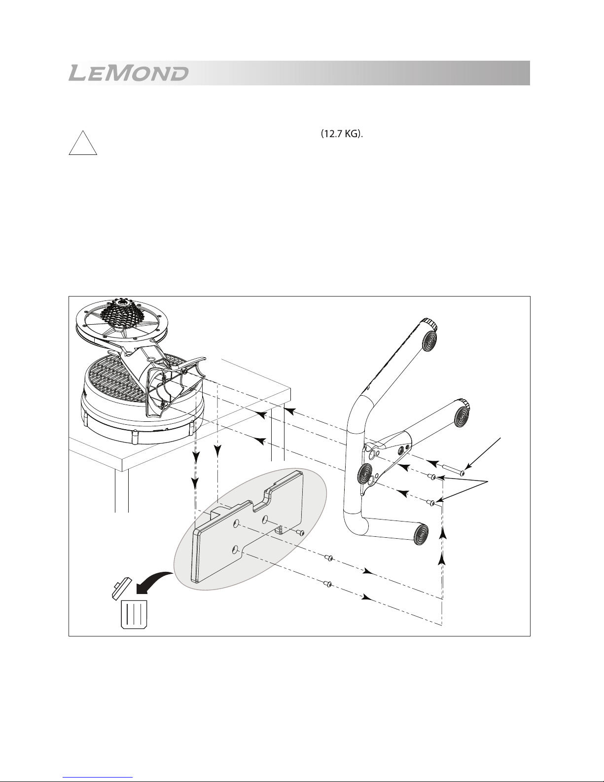
Shift the chain on your bicycle to the smallest sprocket on the rear cassette.1.
Open the rear brake calipers on your bicycle and remove the rear wheel.2.
!
WARNING: CONSULT THE MANUFACTURER’S DOCUMENTATION FOR YOUR BICYCLE OR YOUR
LOCAL BIKE SPECIALIST IF YOU ARE UNSURE ABOUT THE CORRECT PROCEDURE FOR REMOV
ING THE REAR WHEEL OF YOUR BICYCLE.
Loosen the quick-release axle on the3. REVOLUTION and locate the axle spacer on the fan side of the
axle. Be sure to position the spacer properly based on the type of bicycle you are using. (See Figure 2.1)
With the rear wheel removed guide the rear of your bicycle over top of the4. REVOLUTION and ensure
that the chain rests on the smallest sprocket of the cassette on the REVOLUTION and the bicycle chain
stays rest on the axle of the REVOLUTION. (Figure 2.2)
R
oad Bike/ Time Trial Bike Mountain Bike
Spacer Outside
Frame
Spacer Inside
Frame
Note: If you are using a time trial
bike with the REVOLUTION
you will need to remove the
skewer completely to install
your bike.
FIGURE 2.1
Chain on Smallest
Sprocket
Chainstays Resting
on Axle
FIGURE 2.2
The LeMond Revolution is compatible with Shimano®/SRAM® 8/9/10/11-speed cassettes. If your
bicycle is equipped with a Campagnolo® derailleur please follow the instructions on Pg. 12 to change
cassettes and cassette adapter. If you are unsure about the type of derailleur installed on your bicycle
please consult the documentation for your bicycle or visit your local bike specialist to ensure proper
compatibility with the Revolution.

10
With the chain resting on the smallest sprocket and the chain stays resting on the5. REVOLUTION axle,
press down gently on the bicycle seat and roll the bicycle forward. As the bicycle rolls forward it will
drop about an inch as the dropouts seat onto the axle. (Figure 2.3)
C
6.
seated squarely in the dropouts. Both the left and right dropouts should be in contact with the axle
of the REVOLUTION.
Note: Before securing the quick release axle ensure that the bicycle is squarely seated onto the REVOLUTION
by lightly pushing the seat from side to side. If the dropouts do not shift on the axle then the bicycle is
secure and the axle can be tightened. If the bicycle seems unstable return to step 4 above and repeat
the process.
Roll Bike Forward
FIGURE 2.3
BICYCLE MOUNTING INSTRUCTIONS

11
Tighten the acorn nut on the quick release skewer while holding the lever on the opposite side and7.
lock the skewer with the lever. (Figure 2.4)
Note:
your hand. If the lever will not fully close, loosen the acorn nut to allow full closure of the lever.
8. REVOLUTION. If it appears tilted repeat steps 5-7 to
ensure that the dropouts are seated properly on the axle. It the bike still appears tilted use the level-
ing feet to adjust the bike to vertical.
Tighten Skewer
Acorn Nut
Lock Skewer
FIGURE 2.4
BICYCLE MOUNTING INSTRUCTIONS

12
CASSETTE ADAPTOR REMOVAL/INSTALLATION
!
WARNING: IF YOU ARE UNCERTAIN ABOUT YOUR ABILITY TO PERFORM THE PROCEDURE
BELOW PLEASE CONTACT YOUR LOCAL BICYCLE MECHANIC. DAMAGE TO THE EQUIPMENT
WHILE PERFORMING THIS PROCEDURE MAY VOID YOUR WARRANTY.
REQUIRED TOOLS
Chain Whip•
Shimano®/SRAM® Lockring Tool•
Campagnolo® Lockring Tool (if changing to Campagnolo®)•
16mm Socket and Socket Wrench (if changing to Campagnolo®)•
Torque Wrench•
REQUIRED PARTS
•
Campagnolo® C•
INSTRUCTIONS
Remove the axle skewer from the1. REVOLUTION using caution to retain the spacer on the fan side.
Using the chain whip and the Shimano® lockring tool remove the lockring on the cassette.2.
Remove the cassette rings from the cassette adaptor. (Figure 3.1)3.
Note: If you are NOT changing the cassette adaptor, leave it in place on the hub shaft and skip to step 8.
CASSETTE ADAPTOR ASSEMBLY
assette Adaptor (P/N: 250094 or 250094-2) if changing to Campagnolo®
Cassette
Adaptor Cassette
Hub Nut
Cassette
Lockring
FIGURE 3.1
Shimano®/SRAM® 8/9/10/11-speed casstte or Campagnolo® 9/10/11-speed cassette.
We designed the Revolution to be compatible with both Shimano®/SRAM® and Campagnolo® compo-
nents. However, the trainer ships from the factory congured for a 8/9/10/11-speed Shimano®/SRAM®
derailleur. If you need to convert the equipment for the use with a Campagnolo® derailleur, follow the
directions below.

13
CASSETTE ADAPTOR ASSEMBLY
With the cassette removed, use the 16mm socket to remove the hub nut from the shaft at the4.
center of the cassette adaptor. (Figure 3.2)
Remove the cassette adaptor assembly. (Figure 3.1)5.
Before proceeding make sure that the adaptor spacer is still present on the shaft in the hub recess.6.
The adaptor spacer slides freely on the shaft and may have slid out during removal of the cassette
adaptor. (Figure 3.3)
Adaptor
Spacer
FIGURE 3.3
Hub Nut
FIGURE 3.2

14
Install the replacement Campagnolo® adaptor onto the shaft and reinstall the 16mm hub nut.7.
Tighten the nut to 2.5 N m (22 in-lb). (Figure 3.1)
Note: In some cases the bearing inside the adaptor will come loose during installation. If the bearing moves,
be sure that the spacer between the bearings is still in place and push the bearing back into place by
pressing around the outside edge of the bearing.
Note: It may be necessary to turn the adaptor counterclockwise or press the clutch tabs down with your
(Figure 3.4)
Load the new Shimano®/SRAM® or Campagnolo® cassette onto the adaptor. (Figure 3.1)8.
Note: -
tor in one orientation. However, it is possible to install them out of order. Before installing the lockring
make sure that the sprockets are in the correct order and the spacers are installed properly. Refer to the
manufacturers documentation if necessary.
9.
torque stamped on the lockring.
Note: Make sure that the cassette spins freely counter-clockwise. If the cassette does not spin freely remove
the lockring, loosen the hub nut, check that the adaptor spacer is installed, and repeat steps 7-9 above
ensuring proper torque on all fasteners.
Reinstall the axle skewer with the quick release handle on the fan side and follow the instructions10.
on page 15 to mount your bicycle onto the REVOLUTION.
Clutch
Tabs
FIGURE 3.4
CASSETTE ADAPTOR ASSEMBLY

15
BELT REMOVAL
BELT REMOVAL/INSTALLATION
REQUIRED TOOLS
4mm Hex Key or Hex Socket•
3mm Hex Key or Hex Socket•
REQUIRED PARTS
Replacement Belt If Needed (P/N: 250122)•
REMOVAL INSTRUCTIONS
Remove the body side cover by removing the three screws. (Figure 4.1)1.
Loosen the lower belt tensioner screw (A), and then the upper belt tensioner screw (B). (Figure 4.2)2.
3.
INSTALLATION INSTRUCTIONS
Wrap the belt around the pulley assembly.1.
G
2.
4.2 for proper belt route)
!
WARNING: DO NOT FORCE THE BELT ONTO THE FLYWHEEL GEAR. IF THE BELT DOES NOT EASILY
SLIDE ONTO THE GEAR, LOOSEN SCREW B TO MAKE INSTALLATION EASIER. FORCING THE BELT
CAN CAUSE DEFORMATION OF THE TENSIONER PULLEY AND MAKE THE EQUIPMENT INOPERABLE.
Follow the belt tensioning instructions. (p.16)3.
A
B
FIGURE 4.2
FIGURE 4.1

16
BELT TENSIONING INSTRUCTIONS
REQUIRED TOOLS
4mm Hex Key or Hex Socket•
3mm Hex Key or Hex Socket•
INSTRUCTIONS
Remove the body side cover. (Figure 5.1)1.
Loosen the belt tensioner lock screw 1/4 to 1/2 turn. (A in Figure 5.2)2.
Loosen the adjustment screw (B in Figure 5.2).3.
Spin the pulley to ensure proper belt alignment, and tighten the adjustment screw (B) until the belt4.
!
WARNING: USE CAUTION NOT TO OVER TIGHTEN THE BELT. STOP TIGHTENING AS SOON AS
THE BELT IS STRAIGHT.
Tighten the belt tensioner lock screw to secure the belt tension. (A in Figure 5.2)5.
Reinstall the body side cover. (Figure 5.1)6.
FIGURE 5.1
A
B
FIGURE 5.2
BELT TENSIONING

17
PULLEY REMOVAL AND INSTALLATION
PULLEY REMOVAL/INSTALLATION
REQUIRED TOOLS
Chain Whip•
Shimano®/SRAM® or Campagnolo® Lockring Tool•
16mm Socket and Socket Wrench•
Torque Wrench•
4mm Hex Key or Hex Socket•
REQUIRED PARTS
N/A•
REMOVAL INSTRUCTIONS
Remove the belt. (p. 15)1.
Remove the Cassette and Cassette Adaptor (p. 12)2.
Slide the P
3.
INSTALLATION INSTRUCTIONS
Slide the Pulley assembly onto the shaft. (Figure 6.1)1.
Install the Cassette and Cassette Adaptor (p. 12)2.
Install the belt. (p. 15)3.
Tension the belt. (p. 16)4.
FIGURE 6.1

18
PULLEY HUB REPLACEMENT
PULLEY HUB ASSEMBLY REPLACEMENT
REQUIRED TOOLS
Chain Whip•
Shimano®/SRAM® or Campagnolo® Lockring Tool•
16mm Socket and Socket Wrench•
Torque Wrench•
4mm Hex Key or Hex Socket•
REQUIRED PARTS
Pulley Hub Assembly (P/N: 250068 or 250069-2)•
REMOVAL INSTRUCTIONS
Remove the belt. (p.15)1.
Remove the cassette and cassette adaptor. (p.12)2.
Pull the pulley assembly from the pulley shaft.3.
(Figure 7.1)
Place the pulley on a shop towel or other soft surface4.
and remove the 5 screws from the hub assembly.
(Figure 7.2)
INSTALLATION INSTRUCTIONS
Install the replacement hub assembly and be sure to tighten1.
the screws in a star pattern.
Install the pulley assembly back onto the shaft. (Figure 7.1)2.
Reinstall the cassette adaptor and cassette. (p.12)3.
Reinstall the belt. (p.15)4.
FIGURE 7.1
FIGURE 7.2

19
PULLEY FLANGE REPLACEMENT
OUTER PULLEY FLANGE REPLACEMENT
REQUIRED TOOLS
2.5mm Hex Key or Hex Socket or Phillips Head Screwdriver•
REQUIRED PARTS
Drive Pulley Flange (P/N: 250071)•
Note: The Outer (Cassette side) Flange can be replaced without removing the pulley from the unit.
REMOVAL INSTRUCTIONS
Remove the 8-4mm screws from the perimeter on the1.
2.
INSTALLATION INSTRUCTIONS
1.
in a star pattern.
FIGURE 8.1

20
INNER PULLEY FLANGE REPLACEMENT
REQUIRED TOOLS
Chain Whip•
Shimano®/SRAM® or Campagnolo® Lockring Tool•
16mm Socket and Socket Wrench•
Torque Wrench•
4mm Hex Key or Hex Socket•
2.5mm Hex Key or Hex Socket or Phillips Head Screwdriver•
REQUIRED PARTS
Inner Pulley Flange (P/N: 250145)•
INSTRUCTIONS
Remove the belt. (p.15)1.
Remove the cassette and cassette adaptor. (p.12)2.
Remove the pulley. (p.17)3.
Place the pulley on a shop towel or other soft surface and remove4.
Phil-
lips head screwdriver. (Figure 8.2)
5.
a star pattern.
Reinstall the pulley. (p.17)6.
Reinstall the cassette adaptor and cassette. (p.12)7.
Reinstall the belt. (p.15)8.
PULLEY FLANGE REPLACEMENT
FIGURE 8.2
Other manuals for Revolution
1
Table of contents
Popular Fitness Equipment manuals by other brands

Well-Life Healthcare
Well-Life Healthcare WR-2605A OTC Operation manual

Finnlo
Finnlo Speed Bike CRS manual

Bowflex
Bowflex Max Trainer M3 Service manual

Performance
Performance Travel Trac Mag Force manual

Sunny Health & Fitness
Sunny Health & Fitness SF-RW520008 user manual

Weider
Weider Pro 6900 user manual