Lenel LNL-1300-U User manual

1 460989001B
Single Door Controller Module LNL-1300-U Quick Reference
For complete installation details, refer to the UL Listed Access Control and Proprietary Burglar
Alarm Systems in the Hardware Installation Guide, (DOC-600).
The LNL-1300-U Board
The LNL-1300-U provides a solution for interfacing to a Wiegand/ RS-485 type reader and door hardware. It can accept data from a reader with clock/data,
wiegand signaling or 2-wire RS-485 (OSDP), and provides a tri-stated LED control and buzzer control. Two form-C relay outputs may be used for strike
control or alarm signaling. Two supervised inputs are provided for monitoring the door contact and exit push button.
Communication to the interface is accomplished via a 2-wire RS-485 interface. It requires a 12 to 24 VDC power source.
SDC board (Dimensions are in inches [mm])
Package Contents
• LNL-1300-U board
• 1000 ohm resistors
Installation
To install the SDC, perform the installation procedures described in the following sections, in the order in which they are presented.
1. Set baud rate (SW1), address (SW2), and LED control switches.
2. Install jumpers.
3. Mount the board into the enclosure.
4. Wire the supervised alarm inputs for door position and REX exit push button monitoring.
5. Wire the upstream host communication.
6. Wire the relay outputs for door strike and AUX.
7. Wire the downstream interface for the keypad or card reader.
8. Wire tamper input.
9. Wire power and communications inputs.
10. Validate proper operation on power up.
Configuration
The Single Reader SDC Interface Module board contains two (2) 8-position DIP switches that are user-selectable to control addressing, baud rate, and other
functions, and four jumpers used to configure your system.

2 460989001B
Setting DIP Switches
SDC dip switches
Communication Baud Rate (SW1)
Configure the baud rate using SW1 switches 1-4. (Switch 5 is used for LED
control. Switches 6-8 are not used.)
Note: If you are not using OSDP readers, SW1 switch 3 & 4 do not
need to be set as indicated here.
LED Mode
SW1 switch 5 is used for LED control. It is read at boot time. If you make a
change to this setting, be sure to restart.
Device Address (SW2)
Configure the board address using SW2. (Switches 6-8 are not used.)
Baud rate SW1 switch for
host
SW1 switch for
OSDP readers
(Aux ports)
1: 2: 3: 4:
2400 bps off off off off
9600 bps ON off ON off
19200 bps off ON off ON
38400 bps ON ON ON ON
SW1 Switch 5 State
ON LEDs behave as the Access (LNL) series module.
off LED behavior is in Normal Mode
Address SW2 switch
5: 4: 3: 2: 1:
0 off off off off off
1 off off off off ON
2 off off off ON off
3 off off off ON ON
4 off off ON off off
5 off off ON off ON
6 off off ONONoff
7 off off ONONON
8 off ON off off off
9 off ON off off ON
10 off ON off ON off
11 off ON off ON ON
12 off ON ON off off
13 off ON ON off ON
14 off ONONONoff
15 off ONONONON
16 ON off off off off
17 ON off off off ON
18 ON off off ON off
19 ON off off ON ON
20 ON off ON off off
21 ON off ON off ON
22 ON off ON ON off
23 ON off ON ON ON
24 ON ON off off off
25 ON ON off off ON
26 ON ON off ON off
27 ON ON off ON ON
28 ON ON ON off off
29 ON ON ON off ON
30 ON ON ON ON off
31 ON ON ON ON ON

3 460989001B
Installing Jumpers
Jumper configuration
Host communications:
• Jumper J22 pins 1 & 2 for RS-485 reader communications. Install the
jumper on last the SDC on the communications line.
Reader output voltage selection:
• Jumper J12 pins 1 & 2 for +12VDC readers
• Jumper J12 pins 2 & 3 for +5VDC readers
Reader RS-485 termination:
• Jumper J20 pins 1 & 2 for RS-485 reader communications
Note: Do NOT install the jumper for Wiegand/Clock & Data/F2F
Reader Communications.
Reader data line pull-up voltage selection:
• Jumper 9 pins 1 & 2 for +12VDC data lines
• Jumper 9 pins 2 & 3 for +5VDC data lines
Notes: Some readers have data lines pulled up to +5 while the data lines
of other readers are pulled up to +12 VDC. Therefore, you need
to set these to match your reader.
NOT required for RS-485 communications.
Jumper J21 is not used.
Status LEDs
LED Table for Series 2 LNL-1300 Mode
When switch 5 is in the ON position, the LEDs behave like the series 2
LNL-1300.
LED Table for Normal Mode
When SW1 switch 5 is in the off position, the LEDs operate in Normal
Mode.
External tamper (cabinet tamper) must be open for Input LEDs to be on.
When tamper is closed (cabinet door closed) Input LEDs will be off.
Indication LED State
Power-up ALL Off
Initialization D45 Flashing
After initialization D45 Offline: 1 second rate, 20% ON
Online: 1 second rate, 80% ON
Communications D1 ON
Indication LED State
RS-485 panel
communication
D1 ON - Yellow
Reader 1 RS-485
communication
D8 ON - Yellow
Power on D18 ON - Green
Relay 1 D28 ON - Green
Relay 2 D36 ON - Green
Supervised input
I1-I2
D40, D41 Active: ON - Yellow
Inactive: ON - Green
Foreign: ON - Red
Cut: Flashing - Green
Short: Flashing - Red
Ground: Flashing - Yellow
Unsupervised I1-I2 D40, D41 Closed ON - Red,
Open - Off
CPU status D45 Offline: 1 second rate, 20% ON
Online: 1 second rate, 80% ON
Flash Green - Badge Read
External (cabinet)
tamper
D46 Open ON - Red

4 460989001B
CPU status LED D45 possible module error conditions for LED Normal and
Series 2 modes:
Mounting
The SDC can be mounted in the LNL-AL400ULX or LNL-AL600ULX-
4CB6 and the LNL-CTX or LNL-CTX6 enclosure using the Universal
Mounting Plate (UMP) LNL-CONV-U2. The universal mounting plate can
hold up to two (2) LNL-1300-U modules.
Mounting the SDC in the LNL-AL400ULX and LNL-CTX
Mounting the SDC in the LNL-AL600ULX-4CB6 or LNL-CTX6
Error condition Flashing
pattern
Description
No valid
application
firmware
3 Red,
2 Green
The module is not operational.
Firmware must be loaded using a
console, e.g. HyperTerminal with
Xmodem.
Boot loader waiting
on firmware file
3 Red,
1 Green
Console boot loader is waiting on
start of firmware file.
Boot loader loading
firmware file
2 Red,
2 Green
Console boot loader is loading a
firmware file.
Invalid EFL file 1 Red,
2 Green
The EFL specified to be loaded
using the console loader is not a
valid EFL file.
Invalid Xmodem
packet
1 Red,
1 Green
The console loader received an
invalid Xmodem packet and
terminated the firmware
download operation.
Invalid Application
firmware for
module CPU
3 Red,
0 Green
The module is not operational.
Application firmware loaded on
the module will not run properly.
Requires new firmware be loaded
using the console boot loader or
the module must be returned for
repair.
Invalid Boot
firmware for
module CPU
2 Red,
3 Green
The module is not operational.
Boot loader firmware loaded on
the module will not run properly.
The module must be returned for
repair.
Firmware update
failed
1 Red,
3 Green
Firmware update operation was
unsuccessful. Retry and if it fails
continuously, load a different
firmware file.
No valid primary
firmware copy
3 Green,
2 Red
The firmware flash contains 2
copies of the application
firmware. The primary copy is
not valid so the backup copy will
be loaded into the primary copy
and executed.
No valid backup
firmware copy
3 Green,
1 Red
The firmware flash contains 2
copies of the application
firmware. The backup copy is not
valid so the primary copy will be
loaded into the backup copy.
No valid
manufacturing
parameters
3 Green,
0 Red
The manufacturing parameters
which include the serial number,
etc. are invalid. The module must
be returned for repair.

5 460989001B
Wiring
Note: For UL installations, refer to section UL Listed Installations on
page 8.
Supervised (Software Configurable) Alarm Inputs
Wire the I1 and I2 inputs across pins 1 & 2 and 3 & 4 of J15 using a twisted
pair cable, 30 ohms maximum. Terminate each of these inputs with two (2)
1k (1000) ohm resistors (1% tolerance - 0.25 watt).
Note: Resistors must be installed as shown in the SDC wiring diagram
if the installation requires supervision.
SDC input wiring
The two (2) inputs available on the SDC are software configurable alarm
inputs that can be used for alarm device monitoring. Each of these inputs
can be configured, via the Access Control software, as either N/O (normally
open) or N/C (normally closed) in combination with either supervised or
unsupervised wiring. These alarm inputs are connected using Inputs 1 and 2.
Each input that is configured as a supervised alarm must also be terminated
with two (2) 1K (1000) ohm resistors (1% tolerance - 1/4 (0.25) watt. N/O
and N/C alarms are terminated identically). Resistors are provided with the
module.
Install the resistors as close to input device as possible. For cable length
limitations, refer to Specifications.
Upstream Communication
The Single Reader SDC Interface Module uses Port 1 to communicate to the
Intelligent System Controller.
Port 1 is a 2-wire RS-485 interface, that requires the following type of RS-
485 cable: 24 AWG (minimum) twisted pair (with shields). The main run
RS-485 cable should be no longer than 4000 feet [1219 m], 100 ohms
maximum (Belden 9841, West Penn, or equivalent). The drop cables (to
downstream devices) should be kept as short as possible, no longer than 10
feet.
The RS-485 communication is asynchronous, half-duplex, using 1 start bit,
8 data bits, 1 stop bit.
Notes: The (EIA) Electronic Industries Association standard defines
RS-485 as an electrical interface for multi-port communications
on a bus transmission line. It allows for high-speed data transfer
over extended distances (4000 feet [1219 m]). The RS-485
interface uses a balance of differential transmitter/receiver to
reject common mode noise. For increased reliability over the
extended distances, End-Of-Line (EOL) termination is required.
RS-485 must be terminated at both ends of the RS-485 line
(bus). Terminating the line provides a more reliable
communication by minimizing the signal reflection and external
noise coupling. Each component provided has an on-board
terminator. The installer should determine which device is at the
end of the communication line.
Relay Outputs
The Single Reader SDC Interface Module contains two (2) form-C dry-
contact relay outputs, Relay 1 & 2 (K1 & K2). K1 is rated at 5A 30 VDC;
K2 is rated at 1A 30 VDC.
To wire the K1 and K2 outputs, use sufficiently large wires for the load to
avoid voltage loss.
Transient clamping must be provided to protect the output contacts and to
reduce EMI emissions. For AC-powered devices, use MOV across the load.
For DC-powered devices, use a diode across the load.
Input Resistor Table
Alarm Zone
Contact NC
Alarm Zone
Contact NO
Normal 1K 25% 2K 25%
Alarm 2K 25% 1K 25%
Fault – Line Short 0 – 50 0 – 50
Fault – Line Open 15K – 15K –
Fault – Foreign
Voltage
50 – 750
1250 – 1500
2500 – 15K
50 – 750
1250 – 1500
2500 – 15K

6 460989001B
Relay contact (DC strike)
Relay contact (AC strike)
SDC AUX relay wiring
Downstream Reader Communication
The Single Reader SDC Interface Module can communicate downstream
with one (1) card reader. The interface is six wire that includes buzzer and
LED control. The LED and buzzer are both open collector types switching
(sinking) 10mA maximum.
Use 18 AWG wire minimum and maximum length of 500 feet [150m].
Reader power: Voltage 12 VDC +/-10% (optional 5 VDC +/-5% jumper
selectable, current 400 mA maximum to 50°C, derate to 300 mA for 70°C).
Reader wiring
Open Supervised Device Protocol
Open Supervised Device Protocol (OSDP) uses bi-directional
communications between readers and the reader interface, providing
constant monitoring of reader health, improved control of reader operation
and configuration in real-time, and additional communications capabilities
over a single connection, including LCD reader display control.
Wiring for OSDP readers
Elevator Control
OnGuard hardware is capable of supporting elevator control for up to 128
floors. An elevator reader has an input/output module that controls the
access to floors via an elevator.
The OnGuard software must be configured for elevator control. This can be
done from System Administration by selecting the Elevator check box on
the General tab in the Readers and Doors form. The reader’s type, name,
port, address, and access panel can all be defined here as well.
Note: In order for this check box to be available, the access panel to
which this reader module is connected must have Elevator
support enabled on the Options tab.
With elevator control on the LNL-1300 reader, door strike and contact are
not available, and REX (Request to EXit) is disabled.
Addresses assigned to input/output panels do not need to be consecutive. On
the first panel, the inputs/outputs represent the first sixteen floors (e.g.:
Input 1 = first floor, Input 2 = second floor, etc.). The second panel
represents the next sixteen floors (floor 17 through 32), etc.

7 460989001B
Overview of Elevator Control
External (Cabinet) Tamper
An external cabinet tamper is configured by connecting a tamper device
across pins 3 & 4 of J18 on the SDC. If not used, a jumper must be installed
across pins 3 & 4 of J18.
Note: Power fail is not supported on the SDC; therefore no jumper is
required. This is labeled in the diagram as “NOT USED.”
External tamper wiring
Note: Input status LEDs will be off when the tamper device is in closed
position or the jumper is installed.
Power and Communications
For its power input, the SDC requires a 12 to 24 VDC ± 10% power source
for it input power.
Wire the power input with 18 AWG (minimum) twisted pair cable.
Power source wiring
Notes: Be sure to observe polarity.
Do not use an AC transformer to directly power the Single Door
SDC Interface Module.
Intelligent System Controller
Output
Control
Module
Elevator
Reader
(inside cab)
Input Control
Module
Access
Control
System
Elevator Control Room
Up to 128 Outputs -
eight Output Control
Modules
Up to 128 Inputs -
eight Input Control
Modules
Single Reader Interface
Single
Reader
Interface
Module
Single
Reader
Interface
Maximum:
4000 feet
(1219.2 meters)
5 conductors
Power Source Requirements Current
DC power source Isolated, non-switching,
regulated DC power
700mA for 12VDC
350mA for 24VDC

8 460989001B
Specifications
Note: For UL installations, refer to section UL Listed Installations.
The LNL-1300-U is for connection to low voltage, class 2 power-limited
circuits only. These specifications are subject to change without notice.
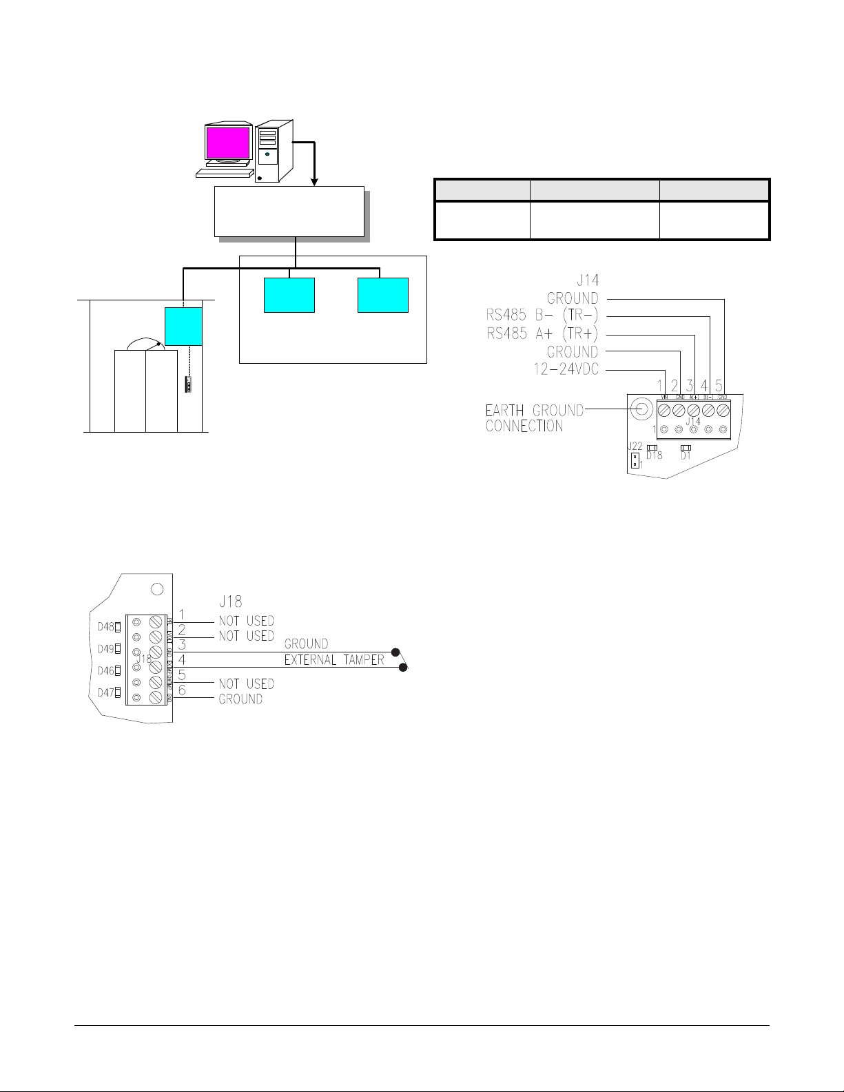
• Primary power:
- 12 to 24 VDC + 10%
- 12 VDC @ 700 mA (includes reader current) nominal
- 24 VDC@ 350 mA (includes reader current) nominal
- 28.7 BTU/hour
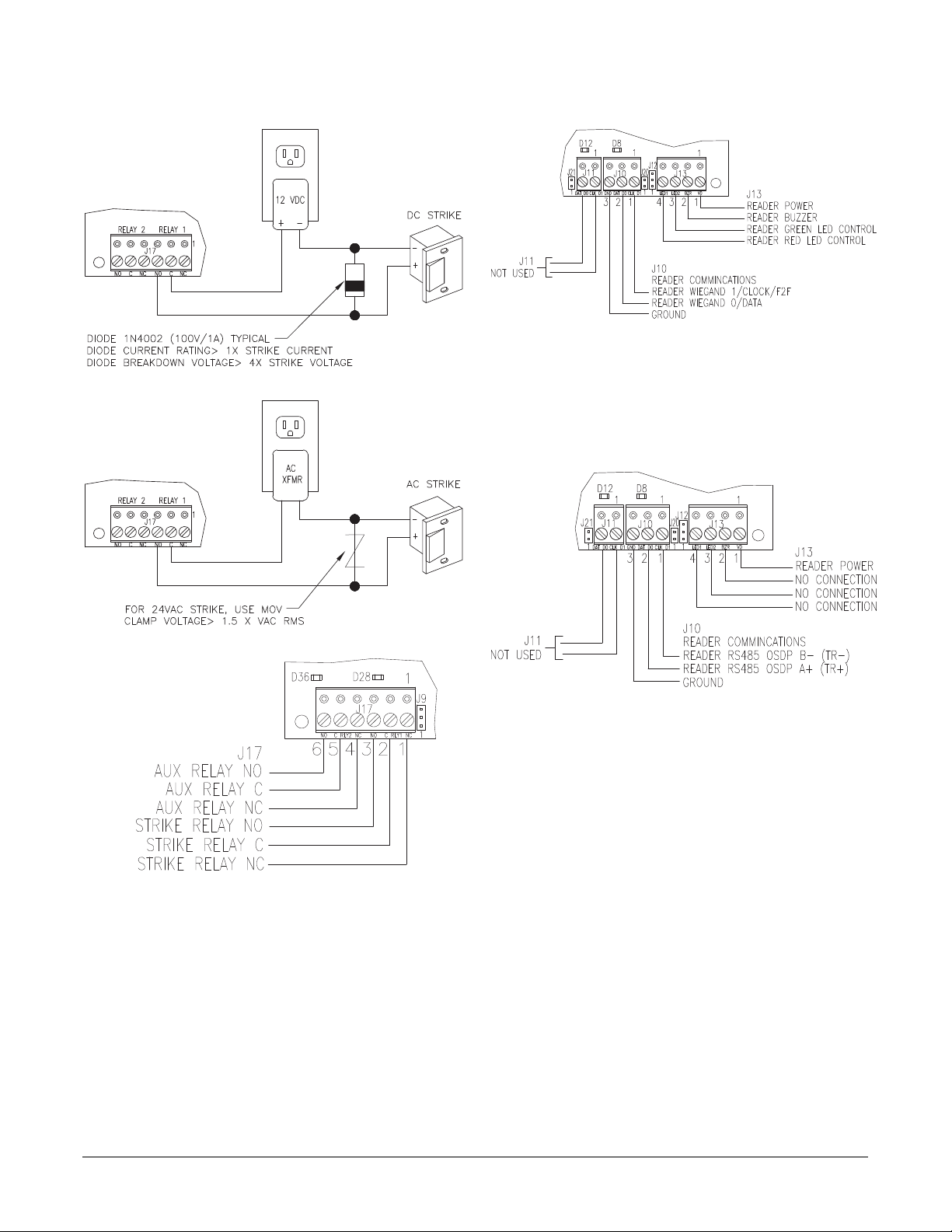
• Outputs: Form-C contacts: Relay 1 and 2 (K1 and K2): 5 A @ 30
VDC
• Inputs:
- Two (2) supervised, End of Line resistors, 1k/1k ohm, 1% 1/4
watt standard
- One (1) unsupervised, dedicated for external (cabinet) tamper
• Reader Interface:
- Reader power: voltage 12 VDC +/-10% (optional 5 VDC +/-5%
jumper selectable, current 400 mA maximum to 50°C, derate to
300 mA for 70°C)
- Reader LED output: open collector type switching (sinking) 10
mA each
- Buzzer output: open collector type switching (sinking) 10 mA
each
- Reader data inputs: 2-wire RS-485, Wiegand, Clock and Data
• Communication: RS-485, 2-wire. 2400 to 38400 bps
• Cable requirements:
- Power: 18 AWG, 1 stranded twisted pair
- RS-485 24 AWG, 120 ohm impedance, stranded twisted pair
with shield, 4000 feet (1219 m) maximum
- Alarm Inputs: 1 stranded twisted pair per input, 30 ohms
maximum
- Outputs: As required for the load
- Reader data (Wiegand, Clock and Data): 18 AWG stranded, 6
conductor, 500 feet (150 m) maximum
- Reader data (RS-485): 24 AWG, 120 ohm impedance, stranded
twisted pair with shield, 4000 (1,219 m) maximum
• Mechanical:
- Dimension: 4.75 x 2.75 x 1.25 in. (121 x 70 x 32 mm)
- Weight: 3.5 oz. (100 g) nominal
• Environmental:
- Temperature: -10 to +70°C (14 to 158°F) operating, -40 to
+85C (-40 to 185°F) storage
- Humidity: 10% at 93°C (199°F) non-condensing operating, 10 to
95% at 85°C (185°F) non-condensing storage
• Certifications:
FCC Part 15
FCC compliance: This equipment has been tested and found to comply with
the limits for a Class A digital device, pursuant to part 15 of the FCC Rules.
These limits are designed to provide reasonable protection against harmful
interference when the equipment is operated in a commercial environment.
This equipment generates, uses, and can radiate radio frequency energy and,
if not installed and used in accordance with the instruction manual, may
cause harmful interference to radio communications.
ETL 294, s319
UL294, UL1076
C-Tick N22193
CE marking
RoHS
Environmental class: Indoor dry
WEEE
European Union directives: 2002/96/EC (WEEE directive): Products
marked with this symbol cannot be disposed of as unsorted municipal waste
in the European Union. For proper recycling, return this product to your
local supplier upon the purchase of equivalent new equipment, or dispose of
it at designated collection points. For more information see:
www.recyclethis.info.
UL Listed Installations
For UL installations, the following must be observed:
• All field wiring terminals are suitable for single wire only.
• Use 22 AWG minimum for wiring of RS-485, Input I1, and reader
data.
• Do not use Input I2 for UL installations; “Do not supervise for UL.”
• RS-485, Clock & Data reader communications is “Not Evaluated by
UL” and therefore cannot be used in UL installations.
• RS-485 4-wire is “Not Evaluated by UL” and therefore cannot be used
in UL installations.
• The use of AC Strikes is “Not Evaluated by UL” and therefore cannot
be used in UL installations.
• Reader power for UL installations: 300 mA maximum for an operating
temperature range of -10 to +49°C (14 to 120°F).
• Environmental for UL installations:
- Temperature: -10 to +49°C (14 to 120°F) operating
- Humidity: 85+/-5% at 30+/-2°C (86°F)
N22193
Table of contents
Other Lenel Controllers manuals