Lenel LNL-400XA-P User manual

© 2020 Carrier. All Rights Reserved. LenelS2 is a part of Carrier. 1 DOC-6019-EN-US — revision 1.001
The LNL-400XA-P Power Supply Unit (PSU)
The LNL-400XA-P is a high-efficiency and cost-effective power supply
designed to house a variety of LenelS2 controllers and modules in an
OnGuard® system.
Featuring a regulated 13.8 VDC output, the LNL-400XA-P supplies
continuous full rated current to load via 4 x PTC (self-resettable) fuses.
Maximum battery life is assured using deep discharge protection to prevent
premature battery failure when operating in standby mode for extended
periods. Two sets of volt-free contacts are provided to signal (i) loss of
mains and (ii) battery and loss of output faults.
The LNL-400XA-P can supply a continuous full-rated current to load plus
an additional 0.5 A for charging a 12 V standby battery.
The universal mains input voltage enables the power supply to be used
across a wide geographical area. The highly efficient switch mode design
ensures low operating costs while generating less heat. The modular
construction simplifies maintenance.
• Continuous full-rated current-to-load
• Universal mains input voltage 90-264 VAC
• High-efficiency electronics for reduced running costs and lower
operating temperatures
• Provided with 4 x 1 A PTC self-reset output fuses
• Mains transient protection circuit
• Lid and removal from wall tamper detection
• Installer-safe design with all high-voltage electronics fully shrouded
• PCB supports and fixings supplied
• Houses a variety of LenelS2 controllers and modules
• PSU status and diagnostic LEDs (mains present and fault)
• Volt-free contact signalling mains failure (EPS)
• Volt-free contact signalling output and battery faults (GEN)
• Full electronic short circuit and overload protection on load output
under mains operation
• Individual battery and output fuse (PTC) protection
• Three-year warranty
Installation
This unit is only suitable for installation as permanently connected
equipment. The PSU is NOT SUITABLE for external installation.
Before installation, ensure that the mains power source has a separate
(approved) disconnect device that is fitted with a fuse or other over-current
protection rated at 3 A maximum. Ensure that the disconnect device has the
appropriate earth fault protection to the applicable standard.
Before connecting the PSU to the mains power source, verify that the
external disconnect device is OFF.
Install the PSU according to all relevant safety regulations applicable to the
application. EQUIPMENT MUST BE EARTHED.
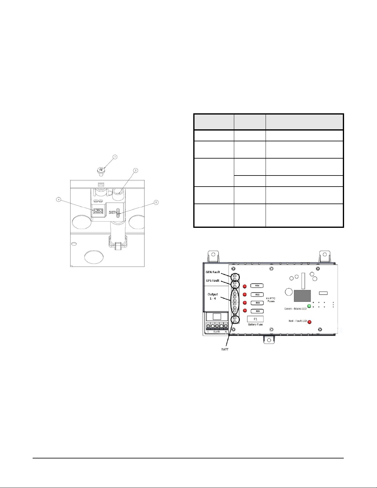
Mounting
1. Mount the PSU securely in correct orientation allowing minimum
clearance. Fasten cables using cable tie securing points as shown.
Mounting the Power Supply
2. Route mains and low voltage output cables via different knockouts
and/or cable entry holes.
Note: Use bushes and cable glands rated to UL94 HB minimum.
Mains Power-up
1. Attach the appropriately-rated mains cable (minimum 0.5 mm2 [3 A],
300/500 VAC) and fasten using cable ties.
2. Apply mains power. Check for 13.8 VDC on load outputs. Ensure that
the green Mains LED is on.
3. Disconnect mains power.
Load Output
1. Attach the appropriately-rated load cable and fasten using cable ties.
Note polarity.
2. Apply mains power. Check green Mains LED is on.
Note: The red LED on the PSU may be on to indicate that no battery
has been connected. This is normal.
3. Verify the load is operating correctly.
4. Disconnect mains power.
Standby Battery
1. Attach supplied battery cables to terminal block and battery.
Note: Ensure correct polarity of battery connections: +ve use red lead;
-ve use black lead.
2. Apply mains power. Ensure that the green Mains LED is on.
3. Ensure that there is no fault indication on the red LED (see Signaling
Outputs).
4. Disconnect mains power. Check that the batteries continue to supply
voltage and current to the load. The Green LED should be off.
Note: Batteries must have sufficient charge to supply the load.
5. Reconnect mains power. The green LED should be on.
LNL-400XA-P 13.8 VDC 4A 4-way PSU with PTC Fuses
Quick Reference

© 2020 Carrier. All Rights Reserved. LenelS2 is a part of Carrier. 2 DOC-6019-EN-US — revision 1.001
Tamper
1. Close the lid/cover and fasten with the supplied lid fixing screw (#1,
sets tamper switch).
2. With the unit mounted on the wall, check that the rear tamper is not in
a position that will affect its operation (for example, over a mortar
course, recess or raised area on the wall).
3. Check that the tamper switch is:
- CLOSED when the lid/cover is closed and the retaining screws
are fitted. Adjust the tamper by using the fine adjustment screw
(#2) and the set position indicator (#3).
- OPEN when the retaining screws are removed and the lid/cover
is open. Adjust the tamper by using the fine adjustment screw
(#2) and the set position indicator (#3).
4. Close the lid/cover and fasten the screws.
Tamper Arrangement
5. Confirm that the tamper circuit (#4) is closed at the control panel.
Operating Instructions
In the event of loss of mains, a battery fault, or a GEN fault, the
corresponding fault signal contacts will open (see Fault Diagnostic Table for
LED indicator status).
If the output of the PSU fails (for example, short circuit load, connection to
a deeply discharged battery), investigate the cause of the failure Rectify the
fault before restoring power to the PSU. If any of the fuses must be replaced,
ensure the correct fuse rating and type is used.
Typical Setup for LNL-400XA-P
Fault Diagnostic Table
Red LED
(Fault)
Green LED
(Mains)
PSU Status
OFF ON Normal. Battery fully charged.
One short flash
every second
ON Normal. Battery charging but not
fully charged.
Flashing:
one second ON
one second OFF
ON Fault. Output fuse or battery fuse
blown, or battery missing.
OFF Fault. No mains, output fuse blown.
One short flash
every 3 seconds
OFF Fault. No mains, battery supplying
load.
OFF OFF Fault. No mains, no output,
batteries disconnected or
completely discharged.

© 2020 Carrier. All Rights Reserved. LenelS2 is a part of Carrier. 3 DOC-6019-EN-US — revision 1.001
Controller and Module Layouts
The LNL-400XA-ENC includes fixing positions for a range of OnGuard®
controllers and modules.
LNL-1000, LNL-1100(-S3), LNL-1200(-S3), LNL-1300(-S3), LNL-1300-U,
LNL-1320(-S3), LNL-2000, LNL-(X)2220, LNL-(X)4420
LNL-1000, LNL-1100(-S3), LNL-1200(-S3), LNL-1300(-S3), LNL-1300e,
LNL-1300-U, LNL-1320(-S3), LNL-2000, LNL-(X)2210, LNL-(X)2220,
LNL-(X)4420
LNL-500, LNL-(X)3300, LNL-8000
LNL-1300e, LNL-(X)2210

© 2020 Carrier. All Rights Reserved. LenelS2 is a part of Carrier. 4 DOC-6019-EN-US — revision 1.001
Specifications Connections
Disposal of Product at End of Life
This product falls within the scope of EU Directives 2012/19/EU Waste
Electrical and Electronic Equipment (WEEE) and 2013/56/EU (Battery). At
the end of life, the product must be separated from the domestic waste
stream and disposed via an appropriate approved WEEE disposal route in
accordance with all national and local regulations.
Before disposal of the product, any batteries must be removed, and disposed
separately via an appropriate approved battery disposal route in accordance
with all national and local regulations. Package used batteries safely for
onward transport to your supplier, collection point or disposal facility.
See Specifications for battery type information. The battery is marked with
the crossed out wheelie bin symbol, which may include lettering to indicate
cadmium (Cd), lead (Pb), or mercury (Hg). For more information, see
www.recyclethis.info.
Note: Risk of fire or explosion if bare battery wires are allowed to
touch.
Compliance
This power supply unit meets the essential requirements of the following
European Directives:
• Low Voltage 2014/35/EU
• EMC 2014/30/EU
• WEEE 2012/19/EU
• RoHs2 2011/65/EU
Input Specifications
Voltage (rated) 100 to 240 VAC
Voltage (operating) 90 to 264 VAC
Frequency 50 to 60 Hz
Maximum Current 2.0 A at 90 VAC
Mains Input Fuse T3.15 A (20 mm 250 VAC)
Output Specifications
Load Output Fuses x 4 PTC Ih 1.1 A / It 2.2 A (hold/trip current) at
20⁰ C
Overload Electronic shutdown until overload or short
circuit removed (under mains power only)
Standby Battery
Battery Type 12 V valve regulated lead acid
Battery Capacity 1 x BS131N 18 Ah max
Battery Charging
Fuse protection
F4.0A (20 mm glass)
Mechanical
Enclosure Dimensions 500 H x 400 W x 80 D (mm)
Weight (excluding battery) 5.8 kg
Enclosure Material Steel - white powder coated RAL 9003
IP and IK Ratings IP30/IK08
Environmental
Temperature -10 to +40° C (operating) 75% RH
non-condensing; -20 to +80° C (storage)
Signaling Outputs
GEN Fault
(general)
0.1 A at 60 VDC N/O volt-free contact. Open when
battery is disconnected, *output fuse fail, battery
fuse fail or output short circuit.|
(*Applies only to O/P 1 of multiple fused units)
EPS Fault
(mains)
0.1 A at 60 VDC N/O volt free contact; open when
loss of mains for more than 10 s.
Lid Tamper 3 A at 125 VAC N/O volt free contact.
Note: Contact open in when lid opened by
normal means or unit is removed from
mounted surface (TAMPER ACTIVE
condition).
+LOAD 1,2,3,4 +ve voltage output to load equipment
-LOAD 1,2,3,4 -ve voltage output to load equipment
EPS Fault Volt-free contacts for loss of mains indication
GEN Fault Volt-free contacts for general faults
(see Signaling Outputs)
+BATT +ve (red lead) connection to standby battery
-BATT -ve (black lead) connection to standby battery

© 2020 Carrier. All Rights Reserved. LenelS2 is a part of Carrier. 5 DOC-6019-EN-US — revision 1.001
Explanation of Symbols
Not all may apply.
Product Warnings and Disclaimers
THESE PRODUCTS ARE INTENDED FOR SALE TO, AND
INSTALLATION BY, AN EXPERIENCED SECURITY
PROFESSIONAL. LENELS2 CANNOT PROVIDE ANY ASSURANCE
THAT ANY PERSON OR ENTITY BUYING ITS PRODUCTS,
INCLUDING ANY “AUTHORIZED DEALER”, IS PROPERLY
TRAINED OR EXPERIENCED TO CORRECTLY INSTALL SECURITY
RELATED PRODUCTS.
For more information on warranty disclaimers and product safety
information, please check https://firesecurityproducts.com/en/policy/
product-warning or scan the following code:
Fault Indication
Mains Present
Protective Earth
Shock Risk - Isolate before attempting access
Certification Level
Do not dispose of in unsorted waste

© 2020 Carrier. All Rights Reserved. LenelS2 is a part of Carrier. 6 DOC-6019-EN-US — revision 1.001
Table of contents
Other Lenel Power Supply manuals