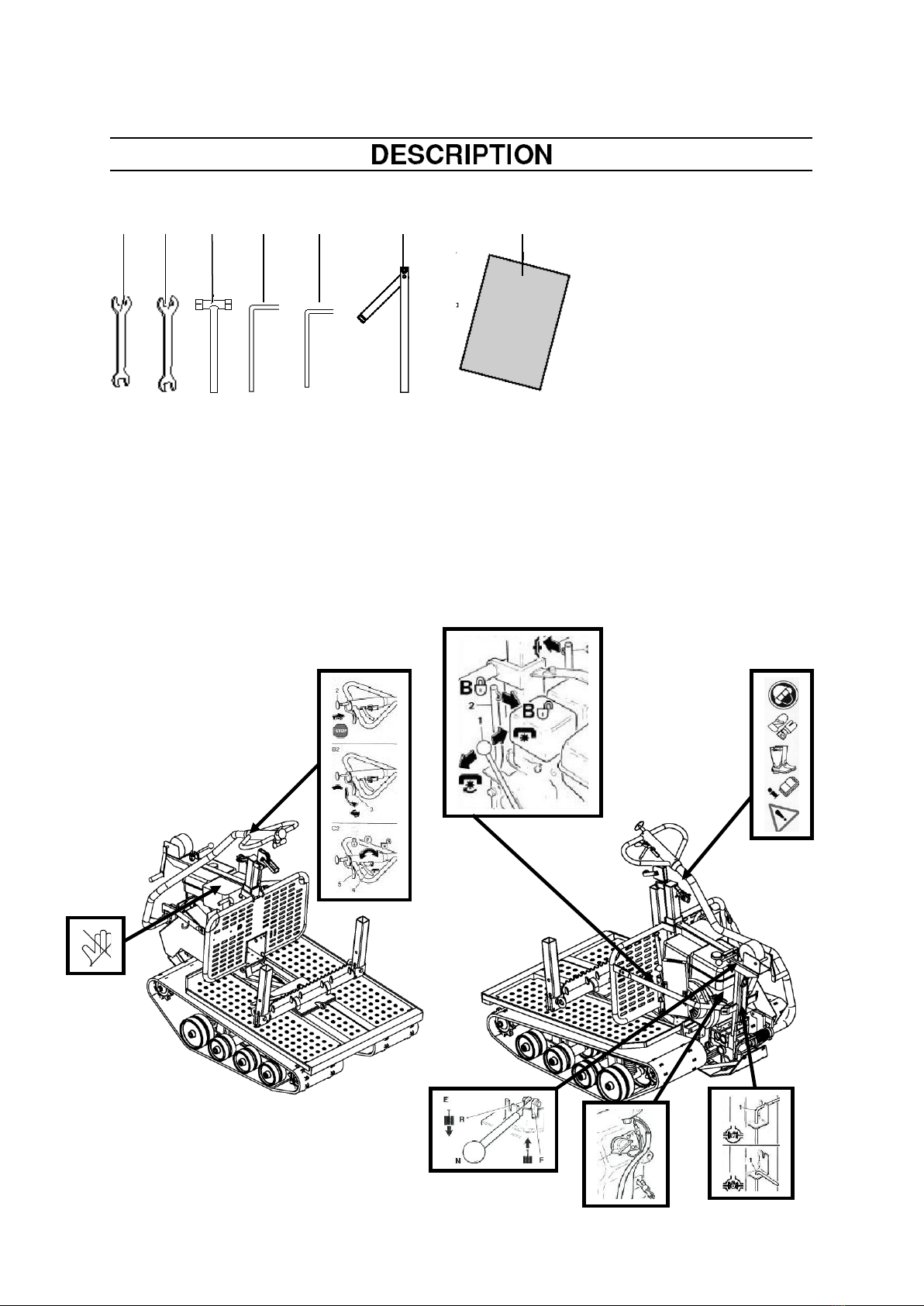
Lennartsfors IronHorse IH 2055 Classic User manual

Edition 2015-03-31
1
Operator’s Manual
Read this Operator's Manual carefully
and make sure you understand it
before attempting to use the Iron Horse.
Models
IH 2055 , IH 2090 , IH 2013
Classic & Flex

Edition 2015-03-31
2
Introduction ............................................ 3
Symbols .................................................. 4
Warning signs ........................................ 4
Safety instructions ................................ 5
Description.............................................. 7
Fuel handling...........................…………. 18
Starting and stopping ............................ 19
Checks before use ………………………. 20
Use....................................……………….. 21
Maintenance........................................…. 28
Trouble shooting …………………………. 35
Technical data.................................…….. 36

Edition 2015-03-31
3
Introduction
This Operator's Manual describes in detail how
the Iron Horse is used, maintained and how
servicing is to be carried out. It also describes the
measures to be taken for maximum safety, how
the safety features are designed and work, as well
as their inspection and any repairs that may
result.
NOTE! The section dealing with safety must be
read and understood by all those who install,
use or repair the Iron Horse.
The Operator's Manual describes getting started,
use and the different maintenance procedures
that can be carried out by the user. More
comprehensive servicing or trouble shooting
should be performed by the dealer's service
personnel.
The Operator's Manual describes all essential
safety details and must be read and understood
by the user before the Iron Horse is used.
Symbols and warning signs shown on the next
page can be found in this Operator's Manual and
on the Iron Horse. A new decal must be applied
as soon as possible if a warning decal on the Iron
Horse has been damaged or is worn so that the
greatest possible safety can be obtained when
using the Iron Horse.
The Iron Horse must only be used for cross-
country transport of, for example, timber,
pulpwood, plants and to transport felled elk. It can
also be used to transport other equipment cross-
country that does not exceed the recommended
weights.

Edition 2015-03-31
4
Symbols
The symbols below are used on the Iron Horse
and in this Operator's Manual.
Warning Signs
The following decals with symbols can be found
on the Iron Horse.
Check regularly that decals are complete and
legible. Replace if damaged.
Engine Stop
Stop control on the engine
Brake locked
Brake open
Parking brake
Fast
Slow
Clutch
Choke
Fuel tap
Differential
Forward
Reverse
Engaged
Disengaged
Helmet, hearing protection
and eye protection should
be used.
Gloves must be worn.
Boots or work shoes with
steel toe-caps and non-slip
soles should be worn.
Read this Operator's
Manual carefully and make
sure you understand it
before attempting to use
the Iron Horse.
Exercise caution.
Keep your hands and feet
away.
Slope max 35 0
Hot surface.

Edition 2015-03-31
5
Safety Regulations
Personal protective equipment
The person or persons using the Iron Horse or
remaining in its close proximity must be equipped
with the personal equipment as set out below:
1. Helmet with hearing protection.
2. Eye protection.
3. Gloves.
4. Boots or work shoes with steel toe-caps and
non-slip soles.
5. First aid kit.
Safety during use
The safety regulations that apply while using the
Iron Horse are documented in respective areas
under the section ”Use” on page 24 - 27.
Warning!
An IronHorse can be a
dangerous machine that can
cause serious or fatal injury if
used incorrectly or carelessly.
It is very important that the
person using the IronHorse
reads and understands the
content of this manual.

Edition 2015-03-31
6
Iron Horse
safety equipment
There are a number of safety devices and guards
to prevent accidents with the Iron Horse. These
are described in the general description of Iron
Horse. See page 16.
The safety devices and guards also require
regular inspection and maintenance. These
measures and intervals are set out in the
”Maintenance” section. See pages 28-34.
Fuel safety
Special safety regulations apply to the fuel
used for the Iron Horse. These
are documented in the section ”Fuel Handling” on
page 18.
Personnel
The following applies to the personnel using the
Iron Horse:
1. Must have read and understood the content of
this Operator's Manual
2. Must not be under the influence of alcohol,
medicines or suffer from tiredness.
3. Good lighting is required when driving outside
daylight hours.
4. Should not be a minor.
Risk Zone
The risk zone is evident from the picture to the
right.
No unauthorised persons may be present in the
risk zone.
Safety during use
The safety regulations that apply while using the
Iron Horse are documented in respective areas
under the section ”Use” on page 24-27.
The operator should observe the following safety
measures before and during use:
1. Check that all safety devices and guards are
fitted and undamaged.
2. Check that no fuel has been spilt on the outside
of the tank or on the ground.
3. Ensure that there are no people or animals
within the Iron Horse's risk zone.
4. Check all controls needed to drive the Iron
Horse.
5. Ensure that all devices needed to secure logs
and accessories on the Iron Horse are used in the
intended manner. See pages 24-26.
6. Check the route, so that no unnecessary
obstacles are in the way, and that you can
operate the Iron Horse in a safe manner.
10 m
10 m
10 m
10 m
FIG. 1
WARNING!
The IronHorse must never be
used if any of the safety devices
or guards are missing, damage
or do not work
WARNING!
The fuel used in the IronHorse
has the following hazardous
properties:
1. The fluid, its vapour, and its
exhaust fumesare
poisonous.
2. Can cause skin irritation.
3. Is highly inflammable

Edition 2015-03-31
7
Iron Horse IH 2055 –IH 2013
Classic
The Iron Horse consists of the following main
parts:
• Engine, gearbox and transmission
• Chassis
• Caterpillar track
• Steering arm
Description:
1. Steering arm
2. Handlebars
3. Brake lever
4. Stop control
5. Throttle
6. Power winch
7. Muffler
8. Log bunk
9. Chassis
10. Caterpillar track
11. Tension wheel bearing
12. Rear bogie wheel
13. Cover over track
14. Lever for log bunk
15. Front bogie wheel
16. Drive wheel
17. Storage box
18. Roll-over bar
19. Screw for height setting
20. Belt guard
21. Protective plate
22. Adjusting bolt for steering arm
23. Balance spring for steering arm
24. Cable cover
25. Differential lock
26. Manual winch
27. Gear lever
28. Fuel tank
29. Chain saw attachment
30. Petrol engine
7
8
9
10
11
1 2 3 4 5 6
30
29
28
27
26
25
24
23
22 21 20 19 18 17 16 15 14 13 12

Edition 2015-03-31
8
Iron Horse IH 2090 –2013 Flex
The Iron Horse consists of the following main
parts:
• Engine, gearbox and transmission
• Chassis
• Caterpillar track
• Steering arm
Beskrivning:
1. Steering arm
2. Handlebars
3. Brake lever
4. Stop control
5. Throttle
6. Power winch
7. Muffler
8. Chassis
9. Caterpillar track
10. Tension wheel bearing
11. Bogie wheel rear
12. Cover over track
13. Front bogie wheel
14. Drive wheel
15. Belt guard
16. Protective plate
17. Adjusting bolt for steering arm
18. Balance spring for steering lever
19. Cable cover
20. Differential lock
21. Gear lever
22. Fuel tank
23. Chain saw attachment
24. Petrol engine
25. Adjustable accessory mount
26. Hydraulic piston
27. Steering arm hydraulic piston
28. Hydraulic pump
29. Hydraulic tank
24
23
22
21
20
19
18
1 2 3 4 5 6
7
8
9
10
25
26
17 16 15 27 28 29 14 13 12 11

Edition 2015-03-31
9
Description:
32. Open ended spanner 10 - 13
33. Open ended spanner 17 - 19
34. Spark plug spanner
35. Allen key 4 mm.
36. Allen key 6 mm.
37. Track adjustment tool
38. This Operator's Manual
Decal placement
The following warning and information decals can be found on the machine. Missing or illegible decals
must be replaced.
32 33 34 35 36 37 38

Edition 2015-03-31
10
Iron Horse (FIG. 2)
The Iron Horse consists of the following parts:
Note! Some parts are optional and are not
included as standard.
• Chassis with mounts for the drive unit, log bunk,
bogie and caterpillar track.
• Load anti-slip guard.
• Load anti-slip guard with integrated power winch.
• Manual winch.
The drive unit consists of the following parts:
• Engine with muffler and fuel tank
• Variator.
• Gearbox with mounts for the steering arm and
drive axles.
• Dog clutch
• Steering brake.
The steering arm consists of the following parts:
• Handlebars with controls
• Adjustable spring for weight balance
• Steering yoke
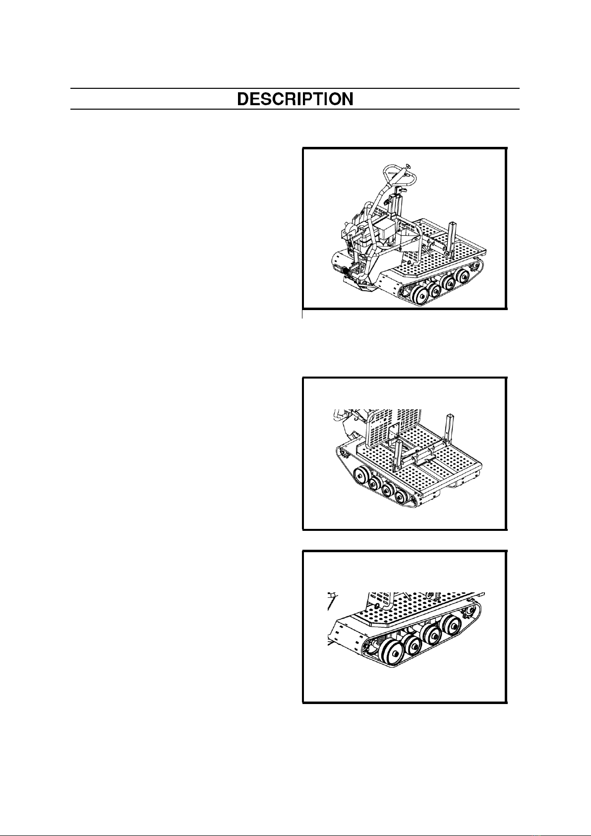
Chassis (FIG. 3) and (FIG. 4)
The chassis is made up of welded square tube
with mounts for the gearbox, load anti-slip guard,
drive axles and bogies. The chassis is also fitted
with perforated sheet metal plates that protect the
tracks. The plates can also serve as a basic
platform to transport loads. The chassis is
equipped with a swing plate to attach the log bunk
and other accessories. The chassis also houses
strong mounts for the machine's bogie and bogie
wheels. The Flex model also has an accessory
mount that is adjustable lengthwise for increased
application possibilities.
Wheel bogie and caterpillar track
(FIG. 3) and (FIG. 4)
The wheel bogie consists of the bogie cradles,
which is supported by bearings on the chassis.
The bogie is available with two types of wheels.
1. Nylon wheels with double wheels on all
axles.
2. Nylon wheels with double wheels on all
axles, supported on bearings and sealed.
The caterpillar track is manufactured of natural
rubber, which is extremely hardwearing and
reinforced with Kevlar and nylon cord. The tracks
are available in two versions.
1. With tooth gaps, which are reinforced by
metal clips and cast epoxy rods.
2. For particularly demanding conditions,
there is a version with internal drive with
interior rubber heels.
FIG 3
FIG 4
FIG 2

Edition 2015-03-31
11
Load anti-slip guard (FIG. 5)
The Iron Horse is equipped with a load anti-slip
guard (with exception of the standard model).
The load anti-slip guard prevents the load from
shifting and damaging the engine. Tubes are fitted
to the guard that act as overriders to prevent
brush and branches damaging the engine. There
is also a chain saw attachment fitted to the
overrider tubes and a bracket to hang the combi-
container for the chain saw.
A toolbox is also fitted on the guard.
Load anti-slip guard with
integrated power winch (FIG. 6)
The power winch is fitted on the load anti-slip
guard. The power winch is driven via a belt
transmission by the petrol engine.
The winch drum is fitted on the load guard and the
winch wire is connected to the winch tower, which
is vertically adjustable and is equipped with a
pulley and swivel, making it possible to winch from
all directions around the machine.
All controls for the power winch are integrated in
the load guard. The power winch is also available
as an accessory and can be retrofitted on the Iron
Horse.
Manual winch (FIG. 7)
There is also a manual winch on all models, with
the exception of the standard model. On
machines with a power winch, the manual winch
is mainly used to anchor the machine when
winching with the power winch.
The manual winch is then attached to an anchor
block located on the power winch tower.
Iron Horse machines without a power winch use
the manual winch to load from the rear.
There is a work roller fitted on the top of the load
guard for the wire to run over to facilitate loading.
FIG 5
FIG 6
FIG 7

Edition 2015-03-31
12
Engine (FIG. 8)
The Iron Horse is driven by a powerful petrol
engine. There are three engine options to choose
from.
The engine is mounted above the gearbox and is
connected to the gearbox via a belt transmission.
The fuel tank and muffler with an integrated heat
shield are also fitted to the engine. The engine's
throttle is operated from the handlebars. The stop
switch is easily accessible on the front of the
engine (FIG. 8 A). The engine is also equipped
with a fuel tap and choke.
Variator (Torque converter)
(FIG. 9)
The Iron Horse is equipped with a variable gear
device, variator (torque converter) (FIG. 9). The
speed and torque output from the gearbox is
governed depending on the load and revs. With
heavy loads, the speed is geared down and in
doing so the torque increases. With lighter loads
the gear ratio is increased and the Iron Horse then
runs faster.
The variator requires maintenance to give optimal
performance, see the service and maintenance
section on page 32.
Gearbox (FIG 10)
The Iron Horse has a cast gearbox made of
spheroidal graphite iron. The gearbox has well-
sized mounting holes for bolting to the chassis. A
protective plate is secured under the gearbox
using large bolts. Downshifting takes place
through straight-cut, hardened cog wheels. The
gearbox has a gear ratio of 1:20. Gear shift for
forward, reverse and neutral. Output axle, where
the dog clutch is fitted and the axle for the brake.
The mount for the steering yoke is located on the
front of the gearbox.
FIG 8
A
FIG 9
FIG 10

Edition 2015-03-31
13
Steering arm (FIG. 11)
The steering arm is attached to the gearbox by a
steering yoke, which is interconnected with the
clutches that release the track. Move the steering
arm to the right or left, releases the clutch on
respective sides. Moving the steering arm further
to either the right or left, slows respective tracks
and the Iron Horse turns. When the steering arm
is placed in the neutral position the machine
drives both tracks and it then runs straight
forwards. The throttle and brake lever as well as a
stop control for the engine are located on the
handlebars. The throttle is positioned in the centre
of the steering arm. The brake lever is placed on
one side of the handlebars. The stop control is
placed in the middle. The weight of the steering
arm is offloaded by means of a spring which is
adjustable. A diff-lock is also fitted to the steering
yoke to lock and reduce steering arm movement
and to lock the steering for different purposes.
Differential lock (FIG. 12)
The differential lock is used to lock the steering,
so that the machine is driven by both tracks,
irrespective of whether the steering arm is moved
to the right or left. The control is easily accessible
on the bracket.
Gear shift (FIG. 13)
Gear shift has three positions. In position (F) the
Iron Horse moves forwards, position (N) is neutral
while in position (R) the Iron Horse reverses.
F: Forwards
N: Neutral
R: Reverse
FIG 11
FIG 12
FIG 13

Edition 2015-03-31
14
Stop control on the handlebars
(FIG. 14)
The Iron Horse is equipped with two stop controls.
One control is easily accessible on the handlebars
(FIG 14.2). When the control is pressed in the
engine stops.
Stop control on the engine
(FIG. 15)
The other control is positioned on the engine and
is a switch with two positions 1 and 0 (FIG. 15).
Throttle (FIG. 16)
The throttle (FIG. 16.3) for the engine is fitted on
the handlebars. When the lever is pressed down
the speed of the engine increases. The throttle is
variably controlled. When the lever is pressed in
fully the engine runs at max. revs.
Brake control (FIG. 17)
Brake lever (FIG. 17.4) is fitted on the handlebars
and is easily accessible when you drive the
machine. Pulling the lever stops the Iron Horse,
which is equipped with a disc brake on the
gearbox.
Locking the brake lever with a catch (FIG. 17, 5)
locks the brake which then serves as a parking
brake.
FIG 14
FIG 15
0
1
FIG 16
FIG 17

Edition 2015-03-31
15
Wire control guard (FIG. 18).
A loop (1) is fitted to the steering yoke to prevent
branches from coming into contact with the wire
control by its mounting on the steering arm.
Balance spring (FIG. 18)
There is a spring (2) fitted around the steering
arm, this can be adjusted. The task of the spring
is to balance the weight of the steering arm
making it weight-neutral.
Adjusting bolt steering arm
(FIG 19)
The adjusting bolt is located on the steering arm
bracket. The lever can be set in one of three
different positions by pulling out the spring-loaded
bolt and moving the lever in the desired direction.
Position (1) is transport mode. The lever is moved
backward so that it reaches minimum height.
Position (2) is when the bolt goes through the hole
and locks the steering arm in the up position. In
Position (3), the lever is moved forward. This is
the usual position when operating the IronHorse.
FIG 18
1
2
1
2
3
FIG 19

Edition 2015-03-31
16
Safety Devices
The Iron Horse is equipped with a number
of safety devices , which are described under the
coming headings.
Belt transmission guard (FIG. 23)
Belt transmission is protected from contact by a
belt guard (1), that covers the transmission
between the engine and the gearbox. On
machines equipped with a power winch the
transmission to the winch is also covered.
Protection for caterpillar track
and hydraulic piston (FIG 24)
The caterpillar track is protected from contact from
the top through the integrated protection (1) on
the chassis. The guard also protects against logs
or other loads damaging the caterpillar track.
On the Flex model with hydraulic piston, there are
two protective plates (2) over the piston to prevent
crushing injuries and damage to the piston and its
hydraulic couplings during loading.
The protective plates may not be removed.
1
FIG 23
FIG 24
1
2
WARNING!
The IronHorse must not be started if
any of the safety devices have been
removed, are defective, or are not
working.

Edition 2015-03-31
17
Stop device on the handlebars
(FIG. 25)
There is a stop control fitted on the steering arm's
handlebars (FIG 25, 2). When the control is
pressed in the engine stops. The control must be
pulled out to start the engine. The control must
always be pressed in when transporting the
machine.
Stop device engine (FIG. 26)
There is a stop switch located on the engine with
the markings 1 and 0 (FIG. 26). When the switch
is in position 0 the current is shorted. Position 1 is
the operating mode.
Throttle (FIG. 27)
The throttle (FIG. 27, 3) is located on the
handlebars. The lever is spring loaded and when
the lever is released the engine idles and the Iron
Horse stops.
Always check the function before starting.
Brakes (FIG. 28).
The brake lever (FIG. 28, 4) stops the Iron Horse.
Move the catch (FIG. 28, 5) into position and lock
the brake lever to engage the parking brake.
FIG 25
FIG 26
0
1
FIG 27
FIG 28

Edition 2015-03-31
18
Fuel
Fuel safety
The following are absolutely forbidden when
fuelling:
• To smoke.
• To have flames or hot objects in close
proximity.
• To have the engine running.
Petrol
Use leaded or unleaded petrol.
The lowest recommended octane grade is 90. If
you run the engine on a lower octane grade than
90 so-called knocking can occur. This leads to an
increased engine temperature, which can result in
serious engine damage.
Refuelling
1. Clean around the fuel cap.
2. Open the fuel cap slowly so that any
excess pressure is released.
3. Tighten the fuel cap carefully after fuelling.
Clean the fuel tank regularly.
The fuel filter should be changed at least once a
year. Contamination in the tanks causes
malfunction.
FIG 31
WARNING!
The fuel used in the IronHorse has
the following hazardous
properties:
1. The fluid, its vapour, and its
exhaust fumes are poisonous.
2. Can cause skin irritation.
3. Is highly inflammable

Edition 2015-03-31
19
Starting a cold engine (FIG. 32)
A cold engine is started as follows:
1. Put the gear shift (1) in neutral (FIG. 33).
2. Open the fuel tap (A).
3. Move the stop switch (B) to the start position (FIG
32, 33)
4. Activate the choke (C).
5. Slowly pull out the starter handle (D) until you feel
some resistance (the starter pawls grip). Now pull
quickly and powerfully.
6. When the engine starts, return the choke.
Stopping the engine
Stop the engine by moving one of the stop controls
(B) to the stop position. The engine stops by moving
one of the stop controls to the stop position. Close
the fuel tap (A).
Starting a warm engine
A warm engine is started in the same way as a cold
engine, except for the following:
The choke is not used on a warm engine.
Starting instructions can also be found in the Manual
for the engine.
.
WARNING!
Observe the following before starting
the engine:
The engine must not be started
without first checking the throttle
and putting the gear shift in neutral
position.
Otherwise the IronHorse can start to
move and cause personally injury.
1
FIG 32
B
FIG 33

Edition 2015-03-31
20
Start the engine as instructed.
Check the function of the throttle (FIG. 35), by
pressing down throttle lever (5) and so the
engine revs increase. When the lever is
released the engine revs should drop to idling
speed.
Checking the steering.
1. Move the gear shift (FIG. 36) to the forward
position. Open the throttle slightly and check
that the Iron Horse moves slowly forwards.
Close the throttle and check that the Iron Horse
stops.
2. Move the steering arm to the right, open the
throttle slightly and check that the Iron Horse
swings to the right. Close the throttle and the
Iron Horse stops.
3. Move the steering arm to the left, open the
throttle slightly and check that the Iron Horse
swings to the left. Release the throttle and the
Iron Horse stops.
4. Repeat the checks with the gear shift (FIG. 36)
in reverse.
Checking the brakes (FIG. 37).
1. Move the gear shift to the forward position and
open the throttle slightly. Check that the Iron
Horse moves slowly forwards.
2. Check that the lock (FIG. 37 A) is released.
Close the throttle and apply the brake (3).
Check that the Iron Horse stops immediately.
Checking the stop control (FIG.
38)
1. Press down the stop control (4) and check that
the engine stops.
WARNING!
Check the controls according to
the following procedures.
If one of the controls is faulty the
IronHorse must never be used
until the fault has been rectified.
FIG 35
5
FIG 36
FIG 37
3
A
FIG 38
4
This manual suits for next models
8
Table of contents
Popular Industrial Equipment manuals by other brands

Conquip
Conquip COSHH Store user guide

Trotec
Trotec SpeedMarker 1600 operating manual

Bosch
Bosch Rexroth ctrlX SAFETY Applications manual

Aeroflex
Aeroflex Weinschel 8310 Operation & service manual

AuCom
AuCom PROFINET CARD instructions

Envirotech Instruments
Envirotech Instruments APM 460 PUF Operation manual

Montanari
Montanari MGS19 Installation, use and maintenance

Siemens
Siemens Sentron 3ZX1812-0WL90-0AA0 operating instructions

Rexnord
Rexnord Thomas Tpack 52 Series Installation and Maintenance

FRIEDHELM LOH
FRIEDHELM LOH Rittal SK 3363 Series Assembly and operating instructions

ATLA COOP
ATLA COOP GAMMA Operating and maintenance instructions

Sino Instruments
Sino Instruments HS710 user manual