Lennox EMEA MONOTOP R290 Operating instructions

INSTALLATION, USER
AND MAINTENANCE MANUAL
N° IN00xxxxx-A
02.2022
Refrigeration monoblock unit
MONOTOP
R290


INDEX
1.
PRODUCT SPECIFICATIONS................................................................................................................................... 3
1.1.
DESCRIPTION ...................................................................................................................................................... 3
1.2.
DESIGNATION ...................................................................................................................................................... 4
1.3.
OPERATING LIMITS ............................................................................................................................................. 4
1.4.
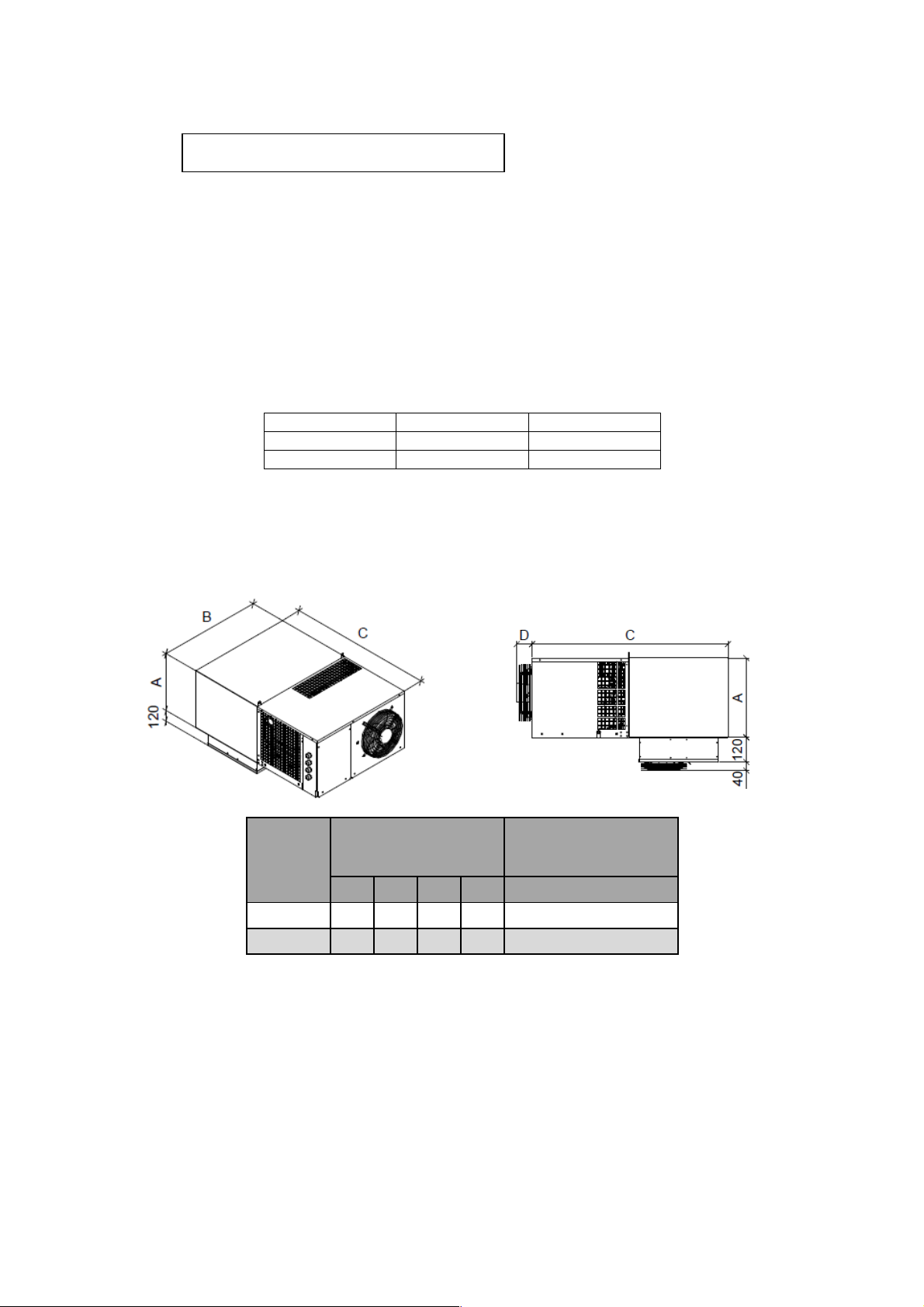
TECHNICAL CHARACTERISTICS AND DIMENSIONS ....................................................................................... 4
1.5.
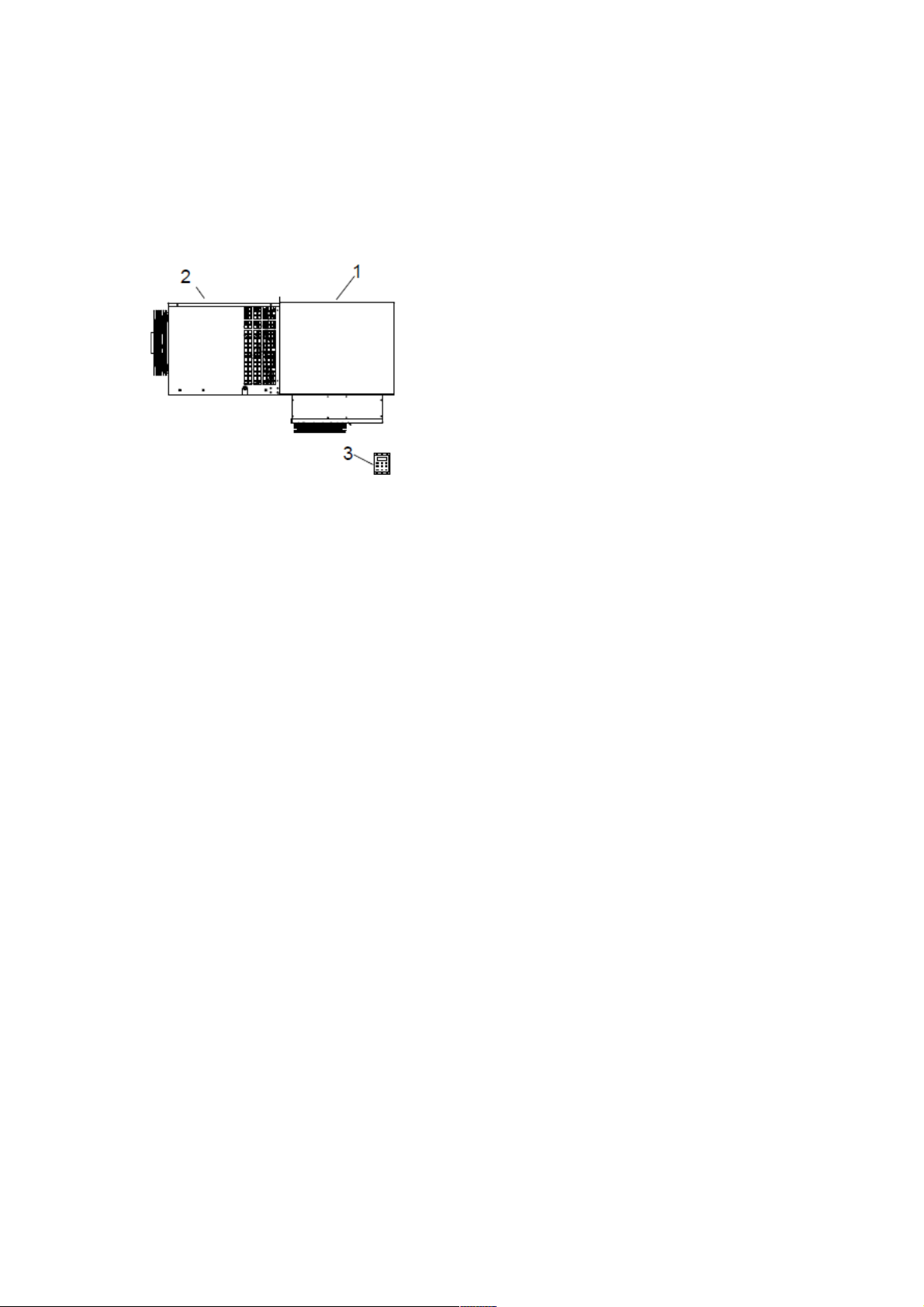
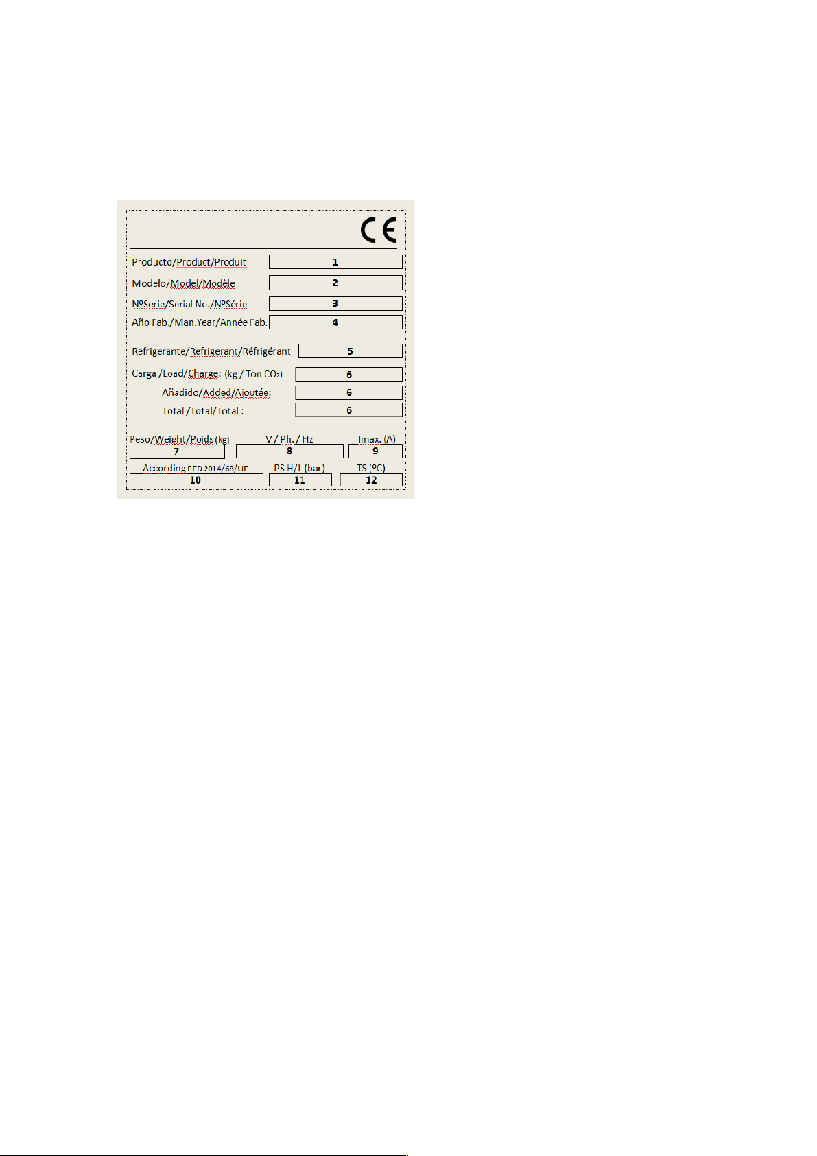
EQUIPMENT DESIGN........................................................................................................................................... 5
2.
UNIT PREPARATION FOR USE ............................................................................................................................... 5
2.1.
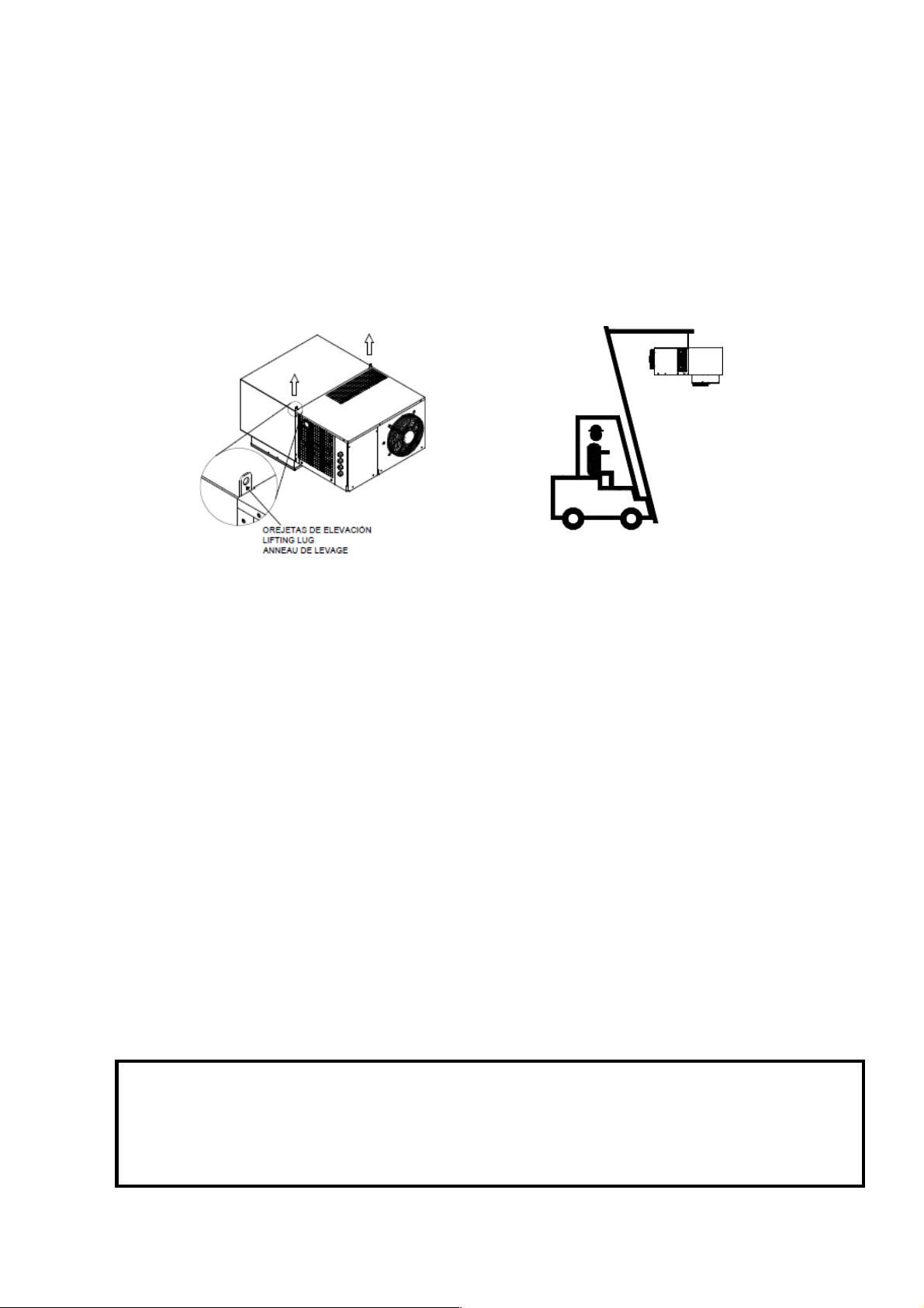
TRANSPORT......................................................................................................................................................... 5
2.2.
IMPORTANT SAFETY WARNINGS ...................................................................................................................... 6
2.3.
INDICATIONS........................................................................................................................................................ 7
2.4.
INSTALLING THE UNIT......................................................................................................................................... 9
2.5.
COMPULSORY SPACE TO BE LEFT AROUND THE UNIT............................................................................... 10
2.6.
ASSEMBLY.......................................................................................................................................................... 10
2.7.
PROTECTIVE DEVICES AND SAFETY MEASURES ........................................................................................ 11
2.8.
DISPOSING OF PACKAGING............................................................................................................................. 11
2.9.
CONTROLS, ADJUSTMENTS AND CHECKS TO BE MADE............................................................................. 11
3.
OPERATING INSTRUCTIONS ................................................................................................................................ 11
3.1.
CONNECTING THE UNIT TO EXTERNAL POWER SOURCES........................................................................ 11
3.2.
ELECTRICAL POWER CONNECTION ............................................................................................................... 12
3.3.
ADJUSTMENT AND CONTROL.......................................................................................................................... 12
3.4.
COLD ROOM LIGHT ........................................................................................................................................... 13
3.5.
CONTROL DEVICE ............................................................................................................................................. 13
3.6.
CONTROL FUNCTIONS ..................................................................................................................................... 14
3.7.
INDICATOR LIGHTS ........................................................................................................................................... 15
3.8.
ALARM SIGNALS ................................................................................................................................................ 15
3.9.
RESETTING THE ALARMS................................................................................................................................. 15
3.10.
PAL/CA ALARM................................................................................................................................................... 16
3.11. P1, P2, P3, P4 ALARM ........................................................................................................................................ 18
3.12.
dA ALARM ........................................................................................................................................................... 19
3.13.
COMPRESSOR ALARM DOES NOT START ..................................................................................................... 19
3.14.
PARAMETER LIST .............................................................................................................................................. 20
3.15.
EXTERNAL COMMUNICATION.......................................................................................................................... 20
3.16.
STARTING UP THE UNIT ................................................................................................................................... 21
3.17.
DIAGRAM OF THE UNIT ELECTRICAL SYSTEM.............................................................................................. 21
4.
MAINTENANCE AND CLEANING ........................................................................................................................... 21
4.1.
MAINTENANCE AND REPAIR OF THE UNIT .................................................................................................... 21
4.2.
ORDINARY MAINTENANCE............................................................................................................................... 22
4.3.
PERIODICAL AND PREVENTIVE MAINTENANCE............................................................................................ 22
4.4.
SERVICING TO BE CARRIED OUT BY QUALIFIED STAFF ............................................................................. 22
4.5.
TECHNICAL PROBLEMS.................................................................................................................................... 23
4.6.
FAILURE ANALYSIS ........................................................................................................................................... 24
4.7.
HOW TO ORDER SPARE PARTS ...................................................................................................................... 25
4.8.
SCRAPPING THE UNIT ...................................................................................................................................... 25

3
1.
PRODUCT SPECIFICATIONS
1.1.
DESCRIPTION
MONOTOP commercial equipments are compact compression cooling units, air-cooled or water-
cooled, for cold storage rooms which have a small volume and for use in medium and low
temperatures, governed by an intelligent control. The power supply is single phase or three
phases depending on the equipment. They consist of:
1-
Evaporator installed inside the cold room
2-
Condenser unit installed externally to the cold
room an insulating. The electric box is placed
here.
3-
Remote control
4-
Unit documentation (user and maintenance
manual, EC conformity declaration, electrical
diagram).
The MONOTOP is a totally compact cooling unit, easy to install and with easy access to the
inside of the unit, making maintenance simple, quick and safe.
-
It is constructed in treated sheet metal with a prepainted finish
-
Its coils are built with copper tube and aluminium fins
-
The evaporator is forced draught type, with air condensation
-
The compressors are hermetic type and they can be supplied to operate with R290
(propane).
The MONOTOP are equipped with:
-
Pre-charged with refrigerant.
-
Hermetic compressor.
-
Refrigerant expansion by capillary system.
-
High pressure switches.
-
Automatic defrosting by hot gas
-
Automatic partial evaporation of defrosting water.
-
Cables for supply, door micro switch and cold room light (2,5 m. each)
-
Remote multifunctional electronic control (with cable of 5m)
-
Watertight cold room light.
-
Condensation control by pressure switch.
-
Filter Drier
-
Probe alert "dirty condenser"
-
One-piece polyurethane injected housing for evaporator.
-
High performance optimized air flow in the evaporator.
-
Install under roof
This manual is an integral part of the equipment and should ALWAYS accompany it. It must be
protected, always, from any possible deterioration during the whole life of the equipment. It
contains the necessary instructions for maintenance technicians and should ALWAYS be easily
accessible to them.
The manufacturer reserves the right to make modifications and / or improve this document
without prior notice.

4
MONOTO(A)P(B) 07(C) P(C)
1.1.
1.2.
DESIGNATION
(A) MONOTO = Compact ceiling refrigeration
(B) P= Positive range – N= Negative range
(C) Model
(D) P= R290
1.3.
OPERATING LIMITS
The MONOTOP units are designed for correct continuous functioning between the
temperature limits shown in the following table.
Máx.
Min.
Refrigeration
+10ºC
-5ºC *
Freezing
-15ºC
-25ºC
* The cold room needs to be designed as if it was a freezing chamber.
Sound pressure level dB (A) <70 db (A) at 10 m of the unit measured in open field
1.4.
TECHNICAL CHARACTERISTICS AND DIMENSIONS
series
UNIT
PANNELCUT
A
B
C
D
100
400
695
975
60
615 x 405
300
498
950
1180
85
865 x 405
1.5.
EQUIPMENT DESIGN
The units are agreed with the those directives:
•
Machine security.…………………………… 2006/42/CE
•
Electromagnetic compatibility ………... …... 2014/30/UE
•
Low voltage ……... …………………………. 2014/35/UE
•
Pressure units………………………………. 2014/68/UE
○
Category art 4.3
○
PS HP/LP 24/14 bar
Attached with each unit corresponding EC Declaration of Conformity

5
The cooling unit must be handled and stored with care, in accordance with applicable
regulations. Please also follow the following instructions:
2.
UNIT PREPARATION FOR USE
2.1.
TRANSPORT
-
Do not start up the unit until 6 hours have elapsed after transportation
-
The unit must be transported and handled in vertical position, protecting it against
water and knocks
-
Never stack the units during transport without being well insured.
-
Never stack the units in the warehouse above the recommended safety limits.
-
Use suitable machinery to move the unit
-
Do not remove the pallet or packaging until the machine is in its final location
The unit must be moved using suitable means of transport and hoisting, and this must be done
by authorised staff. TO SEPARATE THE UNIT FROM THE PALLET, REMOVE THE FIXING
BOLTS.
WARNINGS
Ensure no people are transiting through the area in which the
machine is being transported and handled. RISK OF
KNOCKS, TRAPPING AND CRUSHING.
Whether the unit is packaged or not, it must always be
transported, hoisted and handled in its original position, never
laid down, for safety reasons and to prevent it from falling.
RISK OF BREAKAGE OF THE UNIT, DAMAGE TO THE
BUILDING AND PERSONAL ACCIDENT.

6
CAUTION
To prevent danger of cuts to hands, use protective gloves.
2.2.
IMPORTANT SAFETY WARNINGS
Below are some safety tips to be followed during the installation and use of the unit.
•
The unit must be installed in accordance with the diagrams and recommendations
provided by the Manufacturer.
•
Damage due to improper connections is not covered.
•
A neutral conductor may not be used as a protection conductor, even if it has an earth
connection.
•
The electrical installation on the premises where the unit is installed must be in
compliance with the applicable regulations concerning electrical installations and
electromagnetic protection.
•
For equipments with centrifugal fan, before starting the machine you must connect a
pipe of at least one meter to the fan. This connection must be made so that there are no
openings.
•
Maintenance of the unit must be carried out by qualified, authorised staff, in compliance
with all the stipulations set out in standard EN378 and the regulations applicable to this
effect in each particular country.
•
Guards should only be removed for maintenance or repair
•
It is necessary turn off the unit before removing the fan or remove its guard to perform
maintenance or repair
If the user wishes to use the unit for any purpose it is not designed for, particularly during its use,
or for any servicing they wish to have done, they must ask the Manufacturer to inform them of
any contraindications or hazards that could arise from improper use of the unit.
•
The unit must be used in accordance with the instructions for use and for the purposes
for which it was designed by the Manufacturer. Any improper use of the equipment
constitutes an anomalous condition and may cause damage to the unit itself and be a
serious health hazard for other people.
•
No refrigerant of a type other than that indicated is to be used.
•
No modifications or alterations of the components’ cooling and electrical circuits are to
be made, or any soldering in the compressor or cabling modifications.
•
The end user must protect the installation against fire hazard.
CAUTION
This unit is not designed to work in a saline atmosphere. In this case the condenser
and/or evaporator will need to be protected using the most suitable systems.
CAUTION
This unit is not designed to work in an explosive atmosphere. Its use in a potentially
explosive environment is therefore strictly forbidden.

7
2.3.
INDICATIONS
The manufacturer has applied the use of warning labels and the guidance given in the following
summary table.
1)
Product
2)
Unit model
3)
Unit serial number
4)
Year of manufacture
5)
Type of refrigerant
6)
Amount of refrigerant
7)
Weight of the unit
8)
Tension
9)
Maximum current of the unit
10)
Category of the equipment
11)
Design pressure
12)
Design temperature

8
E27
Salida / Output / Sortle
principal.
! CUIDADO ¡ Peligro de electrocución.
Riskofelectricshock.
Disconnectpowerbeforeservicingunit.
!KONTUZ¡
“CAUTION!
!ATENTION¡
!KONTUZ¡

9
CAUTION
Because the equipment contains R290 refrigerant fluid, the environment in which the equipment
is installed must be well ventilated.
Make sure that the equipment is NOT near heat sources, electrical panels and / or components,
or flammable materials.
2.4.
INSTALLING THE UNIT
To guarantee correct functioning of the MONOTOP for optimising its electrical consumption per Kg of
product stored and to prevent breakdown, it is vitally important that it is placed in a suitable location and
properly used.
The unit must be installed on a cold room for what has to be raised using appropriate means
The unit has pull tabs for easy installation on the camera.
Condenser
-
Ensure air is circulating through the condenser
-
Locate it away from sources of heat
-
Ensure the air entering is as fresh as possible and that the air exiting is not mixed with the air entering
-
Ensure there is sufficient space around the air inlets and outlets
-
Keep the condenser clean
-
Provide an access point for maintenance and servicing
-
The electrical supplies must be protected by suitable magnetothermic switches and differential switches.
-
Provide a drain tube for any condensation that may form and connect it to the drain, located on the side
part of the unit
Evaporator
-
Make sure the cold room door is only kept open when strictly necessary
-
Provide the door with a protective seal to prevent warm, damp air from entering from outside (particularly
for low temperature cold rooms and on premises with a high ambient humidity).
-
Do not place very hot food inside the cold room (it is not a chiller)
-
Do not place food for freezing in the cold room (it is not a cooling tunnel)
-
Leave room for the air to circulate.
-
Seal any points through which air could enter from outside.
NOTE: Commercial MONOTOP units have a system for partial evaporation of the defrost water. This water
must run off to a drain if it does not totally evaporate.

10
2.5.
COMPULSORY SPACE TO BE LEFT AROUND THE UNIT
The unit’s location must allow access for the relevant technical and maintenance service to be carried out, in
compliance with all the safety requirements applicable in the country.
It must be installed in places where good ventilation and air circulation is guaranteed. It must have a
minimum clearance of 0.3m.
Must be installed only on horizontal walls (on the roof)
The minimum recommended insulation thicknesses for the unit are:
-Refrigeration: 60mm
-Freezing: 100mm
2.6.
ASSEMBLY
A)
Must be installed only on horizontal wall (on the roof). Make a hole in the roof of the cold room,
depending of the model, of adequate dimensions HxL, as indicated in the table below.
B)
Raise the unit using the most suitable means, placing it against the hole in the cold room, insert it
from the outside, leaving out the condensing part.
C)
Fix the unit to the roof.
D)
Seal the panel cutting perimeter. To prevent leaks of hot air from the outside.
E)
When the condensation is by water, make sure that the pipes are not smaller than the diameter of
the equipment, complying with the entry and exit instructions.
CAUTION
The water supply temperature for water condensation must be between 10ºC and 20ºC and its
pressure between 1 and 5 bar. The installation of water should be protected from low outside
temperatures.Make sure NEVER close the water supply while the equipment is running.

11
IMPORTANT
The protective devices have been fitted by the manufacturer for user safety during work.
CAUTION
Failure to follow the instructions below may cause injury or severe accidents.
It is absolutely forbidden to weld, braze, cut, grind, or search for a possible leak with an open flame
on a circuit containing A3 refrigerant fluid. Any intervention of this type must become the subject of a
risk analysis.
The equipment (detectors, vacuum pump, etc.) must be compatible with flammable fluids.
Before powering up and operating the unit, always perform refrigerant detection using a suitable
calibrated detector to make sure there is no gas around the unit.
If refrigerant gas leaks out, avoid entering the room, ventilate it as soon as possible and as much as
possible, and prohibit any source of active ignition.
During maintenance, we recommend that operators be equipped with suitable Personal Protective
Equipment (helmet, gloves, goggles, etc.), cut off the power supply and not approach with a potential
source of ignition without first checking that there is no potentially flammable area due to an
undetected leak. With suitable electrical and non-electrical equipment located in ATEX, he will be
able to ventilate the cold chamber to ensure that his intervention is safe.
2.7.
PROTECTIVE DEVICES AND SAFETY MEASURES
The manufacturer has provided the following safety protections:
1.
The metal casing is bolted to the structure.
2.
The fans are bolted to the metal structure.
3.
The fan access is covered by a grille bolted in place.
4.
The motor compressors have thermal protection.
5.
The units have a high pressure switch with manual reset for protection against high pressures.
2.8.
DISPOSING OF PACKAGING
Wooden, cardboard, plastic and polystyrene packaging must be disposed of in accordance with the laws
applicable in the country in which the unit is used.
2.9.
CONTROLS, ADJUSTMENTS AND CHECKS TO BE MADE
Before starting up the unit, check that:
-
the fixing bolts are properly tightened,
-
the electrical connections have been properly made.
-
the electrical connections are properly tightened
In case of opening the unit, check that:
-
no tools have been left inside the unit
-
the assembly has been made correctly,
-
there are no gas leaks,
-
the front cover has been correctly fitted.

12
CAUTION
Before making the electrical connection, check that the mains voltage and frequency are as
indicated on the unit label and that the current remains at a tolerance of +/- 10% with respect to
the nominal value. IF THE CURRENT DOES NOT REMAIN WITHIN THIS TOLERANCE, THE USER
MUST PROVIDE VOLTAGE STABILISERS.
CAUTION
The machine must be connected to the grounding system prior to commissioning. The
system shall comply with the requirements of national regulations.
CAUTION
The line connection must be made with a suitable protection device (magnetothermic switch or
magnetothermic differential switch) selected by the installer or by qualified, authorised staff on
the basis of the line type and consumption indicated on the unit label.
If there is more than one unit in a cold room, each unit must have its own protection device.
CAUTION
Do not connect the door micro switch cables and cold room light cable to the supply line.
3.
OPERATING INSTRUCTIONS
3.1.
CONNECTING THE UNIT TO EXTERNAL POWER SOURCES
3.2.
ELECTRICAL POWER CONNECTION
You must perform a preliminary inspection of the components of the electrical panel, and then proceed to
the electrical connection.
SUPPLY CABLE
a) 230V/1/50-60Hz b) 400/3/50Hz
3 wires ! Blue = Neutral 5 wires ! Blue=Neutral
Yellow/Green = earth Yellow/Green = earth
Brown, Black or Grey = phase Brown = phase
Black = phase
Grey = phase
The unit is equipped with:
- a door micro switch cable (door micro switch not supplied).
- a cold room light cable
- a porthole with an led 230V light bulb.
3.3.
ADJUSTMENT AND CONTROL
The unit is governed by an electronic circuit board and digital control device.
The unit functioning is adjusted by a cold room thermostatic temperature control according to the
temperature setting made by the user. So, when the cold room temperature is higher than the temperature
setting plus a differential value, the cooling cycle starts up, and it stops when the cold room temperature is
the same as the temperature setting.
In this operating mode the digital display of the control shows the cold room temperature.

13
The temperature setting can be viewed by pressing the button and changed by pressing the
and
buttons.
To protect the compressor from successive start-up and stopping, the adjustment system includes an anti-
short cycle timer.
The unit automatically goes into defrost mode after a cooling cycle functioning time of 4 hours. The unit is
supplied with the defrost mode controlled by the internal battery temperature. In this mode, the defrosting
process ends when the internal battery reaches a temperature of 10ºC, or after 25 minutes have elapsed.
After defrosting, the unit remains off for the drip time of 3 min so that all the defrost water can run off.
With the configuration the unit is supplied with, the fans remain off during defrosting.
3.4.
COLD ROOM LIGHT
The cold room light is switched off and on directly from the unit control using the button, providing the
porthole is connected to the cold room light cable. With the optional Winter Kit, the operating of the camera
light on the control board is cancelled.
3.5.
CONTROL DEVICE
This consists of a 3-digit digital display, a keypad with 6 buttons and lights showing the operating modes,
failures and alarms.
1-
Fan warning light
2-
Warning light, defrost
3-
Warning light, cooling mode
4- Alarm warning light
5- Key maximum temperature
6- Minimum temperature key.
7- Compressor warning Light
8- Digital display
9-
Defrost button
10-
Camera light button
11- On / Off button
12- Key. Set point and parameter validation
For viewing and changing the temperature setting. In programming mode, it enables a parameter
to be selected and a value to be confirmed. If it is pressed and held down for 3 seconds, when the
max. and min. temperatures set are shown they will be erased.
For viewing the maximum temperature set. In programming mode it enables the parameter list to
be browsed or the value displayed to be increased.
For viewing the minimum temperature set. In programming mode it enables the parameter list to
be browsed or the value displayed to be reduced.
If this button is pressed and held down for 3 seconds, the defrost cycle begins.
For switching the cold room light on or off.
For switching the unit on or off.

14
CAUTION
After installing and starting up the unit, do not forget to set the maximum and minimum
temperatures.
3.6.
CONTROL FUNCTIONS
•
To switch the unit on or off. -
2. press the button. “OFF” will appear for 5 s.
•
To view the maximum temperature set. -
1.
press the button.
2.
the value will appear on the screen together with the message “Hi”.
3.
press the button and hold it down for 5 seconds to exit.
•
To view the minimum temperature set. -
1.
press the button.
2.
the value will appear on the display together with the message “Lo”.
3.
press the button and hold it down for 5 seconds to exit.
•
To erase the maximum and minimum temperatures set. -
1.
while the minimum or maximum temperature is being displayed,
2.
press the button and hold it down until the message “rST” appears.
•
To view and change the setting. -
1.
press the set button briefly to view the setting
2.
The corresponding indicator light will start to flash.
3.
press the or buttons to change the value.
4.
to complete the process, press set or wait for 10 seconds.
•
To start a manual defrost cycle. -
1. press the button and hold it down for 2 seconds.
•
To access the Pr1 list of user parameters. -
1.
press the set and buttons and hold them down for a few seconds,
2.
the fan and compressor indicator lights will begin to flash,
3.
the first parameter on the list will appear on the display.
•
To change a parameter. -
1.
enter the parameter list,
2.
select the desired parameter using the or buttons, and press set to view its value.
3.
press the or buttons to change the value.
4.
press set to record the new value and go on to the next parameter.
5.
to exit, press set and the button or wait for 15 seconds.
•
To block the keypad. -
1.
press the
and
buttons and hold them down for 3s.
2.
the message “POF” will appear on the display. Now only the setting and the maximum and
minimum temperatures set can be consulted and the cold room light switched on and off.
3.
to unblock the keypad, press the
and
buttons and hold them down for 3s.

15
3.7.
INDICATOR LIGHTS
3.8.
ALARM SIGNALS
Message
Cause
Unit action
P1
Thermostatic sensor failure
Alarm signal. Functioning insafe
mode “Con” and “COF”
P2
Evaporator sensor failure
Alarm signal.
P3
Auxiliary sensor failure
Alarm signal.
HA
Maximum temperature alarm
Alarm signal.
LA
Minimum temperature alarm
Alarm signal.
EE
Data or memory failure
Alarm signal.
dA
Door switch alarm
Alarm signal.
PAL
Pressure switch alarm.
Supply protector relay alarm.
Alarm signal. The unitstops.
3.9.
RESETTING THE ALARMS
The alarm signals are silenced by pressing any button or when the cause of the alarm is rectified (according
to the option entered for parameter “tBA”, the alarm relay can remain active after the alarm has been
silenced).
The sensor failure alarms “P1”, “P2” and “P3” switch off 10 seconds after the failure has been rectified.
The cold chamber temperature alarms “HA” and “LA” switch off when the normal values are reached again
or when defrosting begins.
The door alarm “dA” switches off when the door is closed.
The alarm “PAL” switches off when the unit is turned off.
Indicator
State
Meaning
Compressor indicator
light
On
The compressor is functioning.
Flashing
Anti-short cycle safety device activated.
Voltage relay activated
High or low pressure switches open.
Programming (flashing together with the
fan indicator light).
Fan indicator light
On
The fan is functioning.
Flashing
Programming (flashing together with the
compressor indicator light).
Defrost indicator light
On
Functioning in defrost mode.
Flashing
Defrost complete, drip time
Alarm indicator light
On
An alarm is happening
Energy saving indicator
light
On
Energy saving mode activated
Camera light indicator
light
On
Camera light is on
AUX indicator light
On
Auxiliar relay is on

16
3.10.
PAL/CA ALARM
Indicative of activation of digital input 7-8, means that it has been activated 2 times in 20 minutes.
(Parameters Nps = 2 did = 20).
Possible causes:
1-
PR Voltage Protector see "Network Protector States" on page 17-18.
2-Analyze electrically low pressure switch (PB), high pressure switch (PA).
In case PB is open, indicative of stop due to low pressure, causes:
-
Pressure switch error or electrical connection pressure switch.
-
Coolant leak
-
Compressor has started after activation due to cold demand and the liquid solenoid valve has been
closed. Analyze state coil solenoid, connectin connector coil and terminals 20-N
-
Evaporator fan does not work. Analyze fan output on the microprocessor 18-N.
In the display, under the fan symbol, the red dot must be fixed so that the fan output is activated,
this will happen when pb2 reads 2ºC below the FST value, that is, if the origin parameters have
not been manipulated at 6ºC in the LT equipment and 8ºC in the MT equipment.
-
Check that the jumpers (0), make a good connection. Push bridges.

17
-
Evaluate reading value Pb2, with chamber temperature close to the set point, this value must be
less than Pb1.
In case that PA is open, indicative of stop by high pressure, causes:
-
Error pressure switch or electrical connection pressure switch.
-
Condenser input temperature too high, lack of air renewal or near heat source.
-
Faulty condenser fan, fan start condenser or condensation control.
Directly feed the cable that enters the terminal 33 from line, in case it starts, the Condensation
Control (Pcond) is defective, if it does not start, fan or capacitor () defective. Case of 2 fans, to
check 2nd fan feed directly from line the cable that enters terminal 20.
.
-
Excess refrigerant or air in the circuit
-
Dirty condenser.
States Network Protector
Single phase voltage protector ZHRV5-02

18
Three-phase voltage protector ZHRV5-10
3.11.
P1, P2, P3, P4 ALARM
Indicative of non-detection of the probe in the analog input
Possible causes:
1.
Connection defective probe in the terminal or corresponding terminal according to alarm. Detect bad
contact
Example; Alarm P1, check the connection as well as the contact of the cable tips that enters terminals 01-02.
If the alarm is maintained, change connection 01 through connection 03, if alarm P1 disappears and alarm
P2 appears, it means deteriorated probe P1, replace probe P1, and return to original connection, P1
terminal 01, P2 terminal 03.
2.
If the exchange between connection 01 and 03 was made, the P1 alarm is maintained, the analogue input
deteriorated, change the microprocessor.
Rest of alarm probes; perform the same analysis to determine cause.

19
3.12.
dA ALARM
Indicative of analogue input micro door open.
Possible causes:
1-
Analogue input terminals 09-08, must be closed, check ferrules and connection, possible bad contact.
2-
The micro door cable bridge has been cut. The cable for micro door supplied to be bridged, is connected
to each other.
3-
Wrong micro door contact connection. If it has been connected to a switch micro door, it must be
connected to a normally closed contact, with a closed door.
3.13.
COMPRESSOR ALARM DOES NOT START
1-
If the point under the cold symbol on the display is fixed, it indicates that the digital output of the board is
active by program.
In this case check: the voltage at the output of the board in the case of single-phase equipment (as well as
activation of VSL), the coil A1 - A2 contactor KM for the activation of the compressor in case of three-phase
equipment.
2-
If the fixed point under the cold symbol on the display flashes, it indicates that the digital input of the
safety series (High / Low pressure switch, voltage protector) is open, check causes 1-2 of point 3.10. Micro
digital input door open, check terminals 8-9. Counting anti - short cycle time (parameter AC = 3 minutes).
Low symbol cold A1-A2 compressor contactor KM
Table of contents
Other Lennox EMEA Chiller manuals