3
NOTE: DIAGRAMS & ILLUSTRATIONS NOT TO SCALE.
* See page 16 for Electronic Models conversion from
Natural gas to Propane.
*sledoMcinortcelE
sledoMsaGlarutaN )H/UTB(etartupnI etaRdexiF
,ENFPVBE,ENTSVBE005,73
,ENRCVBE,ENLCVBE000,43
ledoM .oN
ezisecifirO noitavelE )sretem(teeF
.taN.porP
TSVBE FPVBE 23#05# 0054-0 )2731-0(
RCVBE LCVBE 43#05#
Table 1
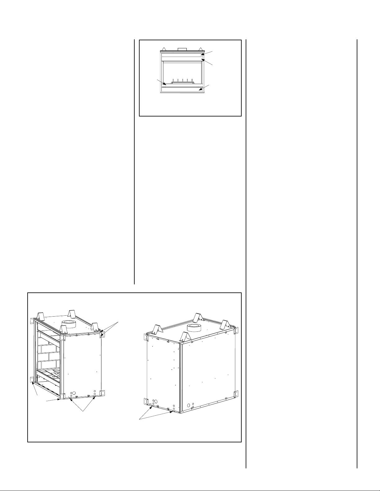
Test gage connections are provided on the
front of the millivolt gas control valve (iden-
tified IN for the inlet and OUT for the mani-
fold side). A ¹⁄₈" NPT test gage connection is
provided at the inlet and outlet side of
the electronic gas control valve.
Minimum inlet gas pressure to these appliances
is5.0 incheswatercolumn(1.24kPa)fornatural
gasand 11.0incheswatercolumn(2.74 kPa)for
propane for the purpose of input adjustment.
Do not use these appliances if any part has
been under water. Immediately call a quali-
fied,professional servicetechnician toinspect
the appliance and to replace any parts of the
control system and any gas control which
have been under water.
Themillivoltappliancesaremanuallycontrolled
and feature a spark ignitor (piezo) that allows
theappliance'spilot gastobelitwithouttheuse
of matches or batteries. This system will still
function in the event of a power outage.
Installations at Altitudes of 0 to 4500 ft.-
Unitsare testedandapproved forelevations
of 0 to 4500 feet (0 to 1372 meters).
Installations at Altitudes above 4500 ft.-
For elevations above 4500 feet (1372
meters), install the unit according to the
regulations of the local authorities having
jurisdictionand,intheUSA,thelatestedition
ofthe NationalFuel GasCode(ANSI Z223.1)
or, in Canada, the latest edition of the
CAN1-B149.1 and .2 codes.
These appliances must be isolated from the gas
supplypiping system(byclosing theirindividual
manualshut-off valve) duringany pressuretest-
ing of the gas supply piping system at test
pressuresequalto or less than¹⁄₂ psig (3.5 kPa).
Carbon Monoxide Poisoning: Early signs of
carbon monoxide poisoning are similar to
the flu with headaches, dizziness and/or
nausea. If you have these signs, obtain
fresh air immediately. Turn off the gas
supply to the appliance and have it ser-
viced by a qualified professional, as it may
not be operating correctly.
Electronic Models -
Electronic models have a fixed rate gas valve.
Input of electronic models is shown in the
following table:
Millivolt Models -
Millivolt models come standard with the
manually-modulated gas valve; flame ap-
pearance and heat output can be con-
trolled at the gas valve. Input of millivolt
models is shown in the following table:
All Models -
Maximum manifold pressure is 3.5 in. w.c.
(0.87 kPa) for natural gas and 10 in. w.c.
(2.49 kPa) for LP/Propane gas.
This appliance may be installed in an af-
termarket permanently located, manufac-
tured home (USA only) or mobile home,
where not prohibited by local codes. This
appliance is only for use with the type of
gas indicated on the rating plate. This ap-
pliance is not convertible for use with
other gases, unless a certified kit is used.
Cetappareilpeutêtreinstallédansunmaison
préfabriquée (É.-U. seulement) ou mobile
déjàinstallée àdemeure si les réglements
locaux le permettent.
Cet appareil doit être utiliséuniquement avec
les types de gaz indiqués sur la plaque
signalétique. Nepasl'utiliseravecd'autresgaz
sauf si un kit de conversion certifiéest installé.
Ne pas se servir de cet appareil s'il a étéplongé
dans l'eau, complètement ou en partie. Appeler
untechnicien qualifiépourinspecter l'appareilet
remplacertoute partie du systèmede contrôleet
toute commande qui ont étéplongés dans l'eau.
WARNING: B-VENTAPPLIANCESARENOT
DESIGNED TO OPERATE IN NEGATIVELY
PRESSUREDENVIRONMENTS(PRESSURE
WITHIN THE HOME IS LESS THAN PRES-
SURES OUTSIDE). SIGNIFICANT NEGA-
TIVELY PRESSURED ENVIRONMENTS
CAUSED BY WEATHER, HOME DESIGN,
OR OTHER DEVICES MAY IMPACT THE
OPERATION OF THESE APPLIANCES.
NEGATIVE PRESSURES MAY RESULT IN
POOR FLAME APPEARANCE, SOOTING,
DAMAGE TO PROPERTY AND/OR SEVERE
PERSONAL INJURY. DO NOT OPERATE
THESEAPPLIANCESINNEGATIVELYPRES-
SUREDENVIRONMENTS.PROVIDINGAD-
EQUATE VENTILATION TO THE APPIANCE
FORCOMBUSTIONAIRWILLELIMINATEA
NEGATIVE PRESSURE ENVIRONMENT.
WARNING: FAILURE TO COMPLY WITH
THEINSTALLATIONANDOPERATING IN-
STRUCTIONS PROVIDED IN THIS DOCU-
MENT WILL RESULT IN AN IMPROP-
ERLY INSTALLED AND OPERATING AP-
PLIANCE,VOIDINGITSWARRANTY. ANY
CHANGE TO THIS APPLIANCE AND/OR
ITS OPERATING CONTROLS IS DANGER-
OUS. IMPROPERINSTALLATIONORUSE
OF THIS APPLIANCE CAN CAUSE SERI-
OUS INJURY OR DEATH FROM FIRE,
BURNS, EXPLOSION OR CARBON MON-
OXIDE POISONING.
These appliances and their individual shut-off
valves must be disconnected from the gas supply
piping system during any pressure testing of that
systematpressures inexcessof¹⁄₂ psig(3.5 kPa).
These appliances must not be connected to
a chimney or flue serving a separate solid
fuel burning appliance.
These appliances are designed to operate on
naturalorpropanegasonly.Theuseofotherfuels
or combination of fuels will degrade the perfor-
mance of this system and may be dangerous.
Maximum inlet gas supply pressure to these
appliances is 10.5 inches water column (2.61
kPa) for natural gas and 13.0 inches water
column (3.23 kPa) for propane.
Table 1
shows the units' gas orifice size
for the elevations indicated.
S'assurerque lebrùleuret lecompartiment des
commandes sont propres. Voir les instruc-
tions d'installation et d'utilisation qui
accompagnent l'appareil.
Provide adequate clearances around air open-
ings and adequate accessibility clearance for
service and proper operation. Never obstruct
the front, back and/or side viewing surfaces of
the appliance.
sledoMtlovilliM
enaporPdnalarutaN sledoMsaG )H/UTB(etartupnI detaludom-yllaunaM
,MNFPVBE,MNTSVBE ,MPFPVBE,MPTSVBE 005,73OT000,03 000,43OT000,72
,MNRCVBE,MNLCVBE MPRCVBE,MPLCVBE 000,43OT000,82 000,43OT000,72