manuals.online logo
Brands
  1. Home
  2. •
  3. Brands
  4. •
  5. Lennox
  6. •
  7. Accessories
  8. •
  9. Lennox CS User manual

Lennox CS User manual

©2014 Lennox Industries Inc.
Dallas, Texas, USA
RETAIN THESE INSTRUCTIONS
FOR FUTURE REFERENCE
Adjust Temperature - Quick Reference
See figure 1 to adjust the heating and cooling setpoints. If
the setpoints are not displayed, press any button.
General
The Comfort Sensor (CS) and Comfort Sensor-Zoning
(CSZ) are temperature sensors which will communicate
with the L Connection network. In addition, the CSZ is used
as a zone controller. Both CS and CSZ are available with
humidity and CO2sensing options.
Features:
Adjustable temperature setpoints
Resume program operation
Change the occupancy status
The CSZ will communicate on the ZoneBus to a Zone Link
control. The Zone Link will control rooftop unit heating,
cooling, and ventilation for all of the zones on the ZoneBus.
Display
The following readings will be displayed on start-up.
Zone temperature
Unit status (if unit is operating)
Occupied (if unit is in occupied mode)
To display additional information, M1/M2 electronic
configure to order (ECTO) or M3 parameter settings may
be adjusted. See the installation instructions provided with
each sensor.
Refer to the following steps and the appropriate number in
figure 2 for a description of each readout.
USER'S GUIDE
Comfort Sensor (CS) and
Comfort Sensor Zoning
(CSZ)
CONTROLS
505218M
7/2014
Supersedes 11/2010
Press to
increase
the set
point.
Press to
lower the
setpoint
Press to change
to other setpoint.
Heating Setpoint
(adjustable when flashing)
Cooling Setpoint (adjust
able when flashing)
Note - CS/CSZ may be set to prevent adjustment. The setpoint
range may also be limited. Check with the building manager or
maintenance personnel if setpoints won't change.
Press to
heat or cool
after hours.
Figure 1. Change Setpoints
1. Cooling Setpoint or Damper Position. When the ECTO
or M3 Parameter is set to display the damper position,
any button may be pushed to display the setpoints.
Damper position is available for use with CSZ sensors
only.
2. Heating Setpoint or Relative Humidity. When the
ECTO or Parameter is set to display the relative
humidity, any button may be pushed to display the
setpoints. CS/CSZ must be equipped with RH option
to display RH.
3. Resume Program. Displayed when override mode is
returning to a scheduled program.
4. Override Mode. Displayed when a scheduled program
has been overridden. Also referred to as After Hours
Override.
5. Zone temperature.
6. Operation Status. Either HEAT or COOL will be
displayed when the zone is operating in heating or
cooling mode. The appropriate readout will blink if the
zone is requesting either heating or cooling and the
zone is not yet being serviced.
Litho U.S.A.
Page 2
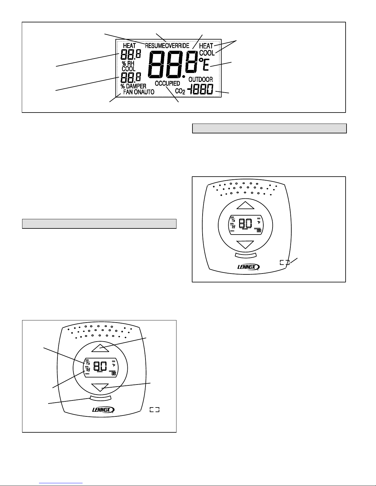
5Zone Temperature (high resolution shown)
7Degrees F or C
2Heating Setpoint or
Relative Humidity
1Cooling Setpoint or
Zone Damper
Position (CSZ only)
8Outdoor Temperature or CO2level
10 Fan Status (CS only) 9Displayed during occupied time period
4Override Mode3Resume Program
6Operation Status
Figure 2. Display description
7. Degrees Fahrenheit (F) or Celsius (C).
8. Outdoor Temperature or CO2. CO2level shown in
parts per million. The CS/CSZ must be equipped with
CO2option to display CO2.
9. Occupied Status. Displayed when the zone is in
occupied mode. Nothing is displayed in this area
during the unoccupied time period.
10. Fan Status. CS only. If enabled, the unit fan control
status is displayed, either FAN ON (continuous) or
FAN AUTO (cycles with heating or cooling operation).
Refer to the CS instructions to enable fan status.
Change Heating and Cooling Setpoints
Use the following steps and figure 3 to change setpoints.
1. Press either arrow button. The setpoint for the
currently operating mode will blink.
2. Use the arrow buttons to change the setpoint for the
currently operating mode.
3. Press the select button to change to the other setpoint.
Use the arrow buttons to change the other setpoint.
4. Press the select button for 1 second to enter the new
setpoints. New setpoints will also be entered if no
buttons are pressed for 4 seconds.
Press to
increase
the
setpoint.
Press to
lower
the
setpoint
Select
Button
Heating
Setpoint
Cooling
Setpoint
Note - CS/CSZ may be set up to limit the range of setpoint
adjustment or disable setpoint adjustment.
Figure 3. Change Setpoints
Override / Occupancy Status
Initiating Override
Press the button on the right side of the CS/CSZ to
override the Network Control Panel (NCP) scheduled
program for that zone. See figure 4. The zone setpoint will
change to the override values.
PRESS TO OVERRIDE THE SCHEDULED PROGRAM
OVERRIDE
BUTTON
Figure 4. Occupancy Override
The scheduled program can also be overridden by
changing the setpoints using the buttons on the CS/CSZ.
See previous section. The new setpoints will be used for
the override period (default 2 hours). At the end of the
override period setpoints will return to the scheduled
program values.
Length of Override
The override period is determined by:
The NCP (when installed)
The Zone Link (CSZ installed but no NCP)
Unit Controller (CS installed but no NCP)
Manual Mode
In manual mode the override button toggles between
occupied and unoccupied mode for that zone. The
occupied time period does not apply. Manual mode occurs
when:
The NCP is set to MANUAL
A CS is on a network without an NCP or ZL
Resume Occupied Setpoints
To discontinue the override period:
Page 3 COMFORT SENSOR SERIES
1. Press the select button and the OVERRIDE readout
will blink.
2. Use either arrow button and the RESUME readout will
blink. (The arrow buttons will toggle between
OVERRIDE and RESUME.)
3. Press and hold the select button to return to occupied
setpoints. New setpoints will also be entered if no
buttons are pressed for 4 seconds.
Zone Data Display
Press and hold the select button for 2 seconds to switch to
the zone data screen. The CS/CSZ can be setup to display
the following information:
RH
CO2
Damper position
Outdoor air temperature
NOTE - When both CO2and outdoor temperature are
used, the display will alternate between the two values.
PRESS AND
HOLD FOR 2
SECONDS TO
DISPLAY ZONE
DATA
Figure 5. Zone Data Screen
Fan Control CS Only
The CS DIP switch must be set to display the fan function.
Refer to the CS installation instruction. Press the select
button to display the fan operation. See figure 6.
Press the arrow buttons to change the fan cycling.
PRESS FOR 1
SECOND TO
DISPLAY THE
TYPE OF FAN
OPERATION
FAN ON = Continuous fan
FAN AUTO = Fan cycles with heating or cooling operation.
Figure 6. Fan Control

Other Lennox Accessories manuals

Lennox LGH420 User manual

Lennox

Lennox LGH420 User manual

Lennox 59M05 User manual

Lennox

Lennox 59M05 User manual

Lennox 47W36 User manual

Lennox

Lennox 47W36 User manual

Lennox 59M04 User manual

Lennox

Lennox 59M04 User manual

Lennox LCH Series User manual

Lennox

Lennox LCH Series User manual

Lennox 21L07 User manual

Lennox

Lennox 21L07 User manual

Popular Accessories manuals by other brands

Pkm GKS 110 instruction manual

Pkm

Pkm GKS 110 instruction manual

Ridder Newton 100-S installation manual

Ridder

Ridder Newton 100-S installation manual

S+S Regeltechnik Thermasgard ETF 6 Series Operating Instructions, Mounting & Installation

S+S Regeltechnik

S+S Regeltechnik Thermasgard ETF 6 Series Operating Instructions, Mounting & Installation

Huawei BTS3900A Commissioning Guide

Huawei

Huawei BTS3900A Commissioning Guide

socomec TF Series quick start

socomec

socomec TF Series quick start

Compu-aire CKC AYAN IV-IR NANO SERIES Installation and operational maintenance manual

Compu-aire

Compu-aire CKC AYAN IV-IR NANO SERIES Installation and operational maintenance manual

Motorline professional COFRE 600 VOLANTE installer and user manual

Motorline professional

Motorline professional COFRE 600 VOLANTE installer and user manual

4B Watchdog Super Elite Operation manual

4B

4B Watchdog Super Elite Operation manual

TUYA TM001-ZA Product specification

TUYA

TUYA TM001-ZA Product specification

Interlogix SDX-135Z user guide

Interlogix

Interlogix SDX-135Z user guide

Jaquet Green line E12A operating instructions

Jaquet

Jaquet Green line E12A operating instructions

Trane CLCH-IN-18A Installation

Trane

Trane CLCH-IN-18A Installation

OXO Good Grips user manual

OXO

OXO Good Grips user manual

Immergas 3.030906 Instruction and warning book

Immergas

Immergas 3.030906 Instruction and warning book

elsner elektronik R 24 V Technical specifications and installation instructions

elsner elektronik

elsner elektronik R 24 V Technical specifications and installation instructions

SICK GTB2 Flat Series operating instructions

SICK

SICK GTB2 Flat Series operating instructions

Honeywell 5898 installation instructions

Honeywell

Honeywell 5898 installation instructions

DeWalt DW0250 user manual

DeWalt

DeWalt DW0250 user manual

manuals.online logo
manuals.online logoBrands
  • About & Mission
  • Contact us
  • Privacy Policy
  • Terms and Conditions

Copyright 2025 Manuals.Online. All Rights Reserved.