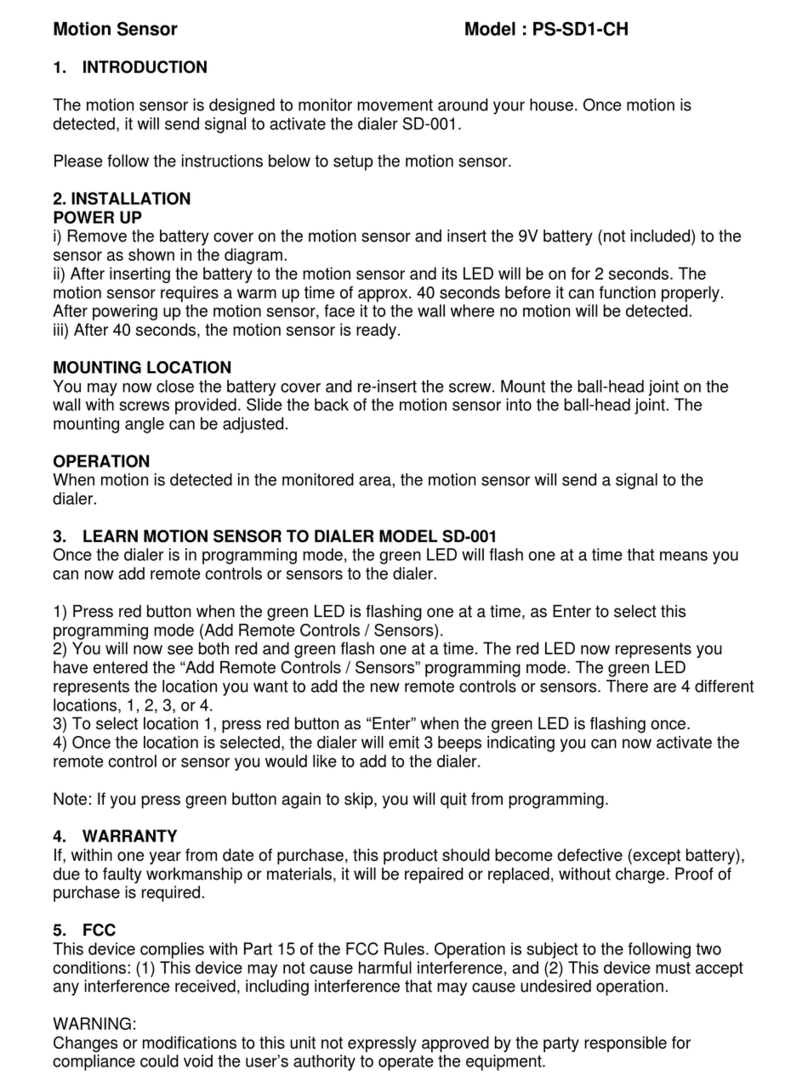
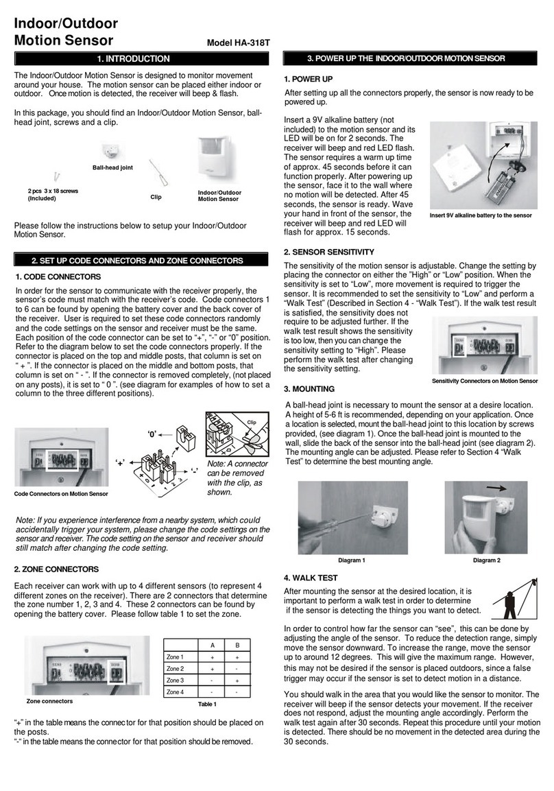
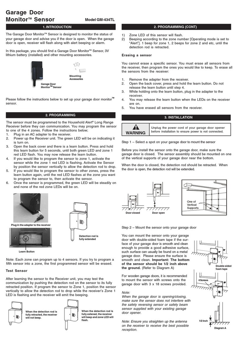
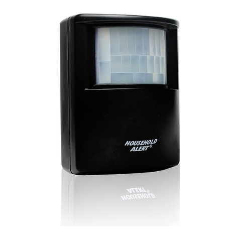
1. INTRODUCTION
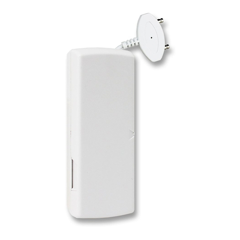
Flood Sensor Model FS-433
The Flood Sensor is designed to alert you when there is water present
& potential flooding. Place this sensor along the basement wall, near the
water heater, washing machine etc. When the probe of the sensor is
covered with water, the sensor will send a signal to one of the Skylink’s
receivers (Security Control Panel SC-001, Emergency Dialer AD-433S,
Audio Alarm AA-433, Silent Alarm SW-433) and these receivers will
perform their tasks. You must program the sensor to these receivers
before they can recognize each other.
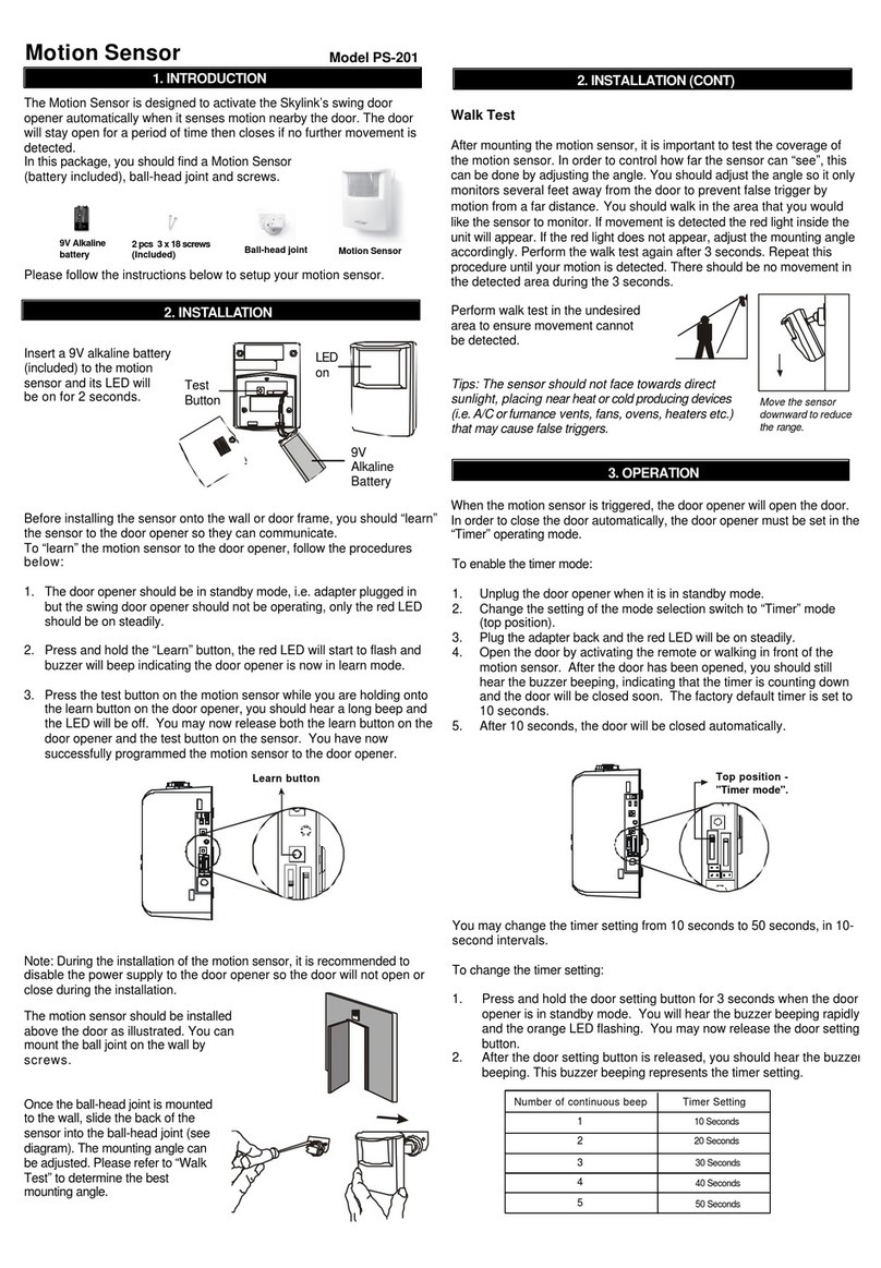
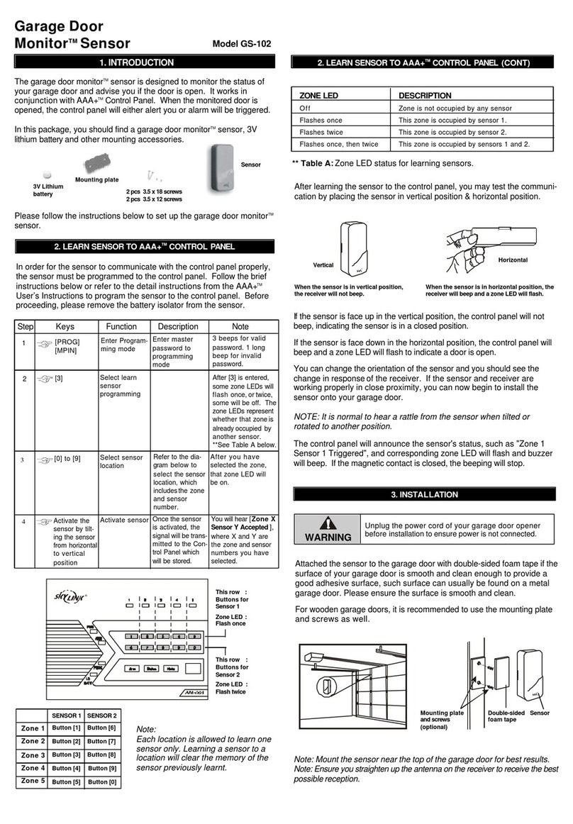
In this package, you should find a Flood Sensor
(battery inside), double-sided foam tape and
screws.
Please follow the instructions below to setup your flood sensor.
2 pcs 2.6 x 12 screws
2 pcs 3.5 x 20 screws
(Included) Flood Sensor
(battery inside)
Double-sided foam tape
1. Enter the current MPIN (Master Personal Identification Number) on the
SC-001.
2. Press [B]
3. Press the number key to identify which zone to add the Flood Sensor
to, zone [1, 2, 3, 4]. It is not recommended to program this sensor to
zone 1 or 2 because these zones are intended for Delay Mode.
4. The zone light(s) will flash for eight seconds.
5. While the zone light(s) are flashing, press [ ].
Now both the green and red lights flash for 30
seconds.
6. While the zone lights are flashing, activate the
flood sensor by pressing the learn button on the
sensor. The red LED light on the Flood Sensor
will turn on. You will hear a long beep from the
control panel, the zone lights will stop flashing
and the Flood Sensor will now communicate
to that zone.
2. PROGRAM THE FLOOD SENSOR TO THE SECURITY CONTROL
PANEL (SC-001)
*
1. With only the “ON” light lit on the Audio Alarm, press and hold the learn
button located on the bottom of the Audio Alarm.
2. While pressing down on the learn button, activate the Flood Sensor by
pressing the learn button on the sensor. The red LED light will flash.
3. If a connection has been made, the Audio Alarm will stop beeping and
make a continuous tone until the black learn button on the Audio Alarm
is released.
4. Arm the AA-433 in chime mode. Test the sensor by pressing the buttonon
the flood sensor again. If the Audio Alarm beeps, they are communicating.
3. PROGRAM THE FLOOD SENSOR TO THE AUDIO ALARM
(AA-433)
1. Pr ess [L], [5] when in clock mode, the display will show “L5 Id codE”.
2. Activate the Flood Sensor within 5 seconds by pressing the learn button
on the sensor. The red LED light of the Flood Sensor will be on when
the button on the sensoris pressed.The displaywill returnto clockmode
once the Flood Sensor has been learned.
3. If the Flood Sensor detects any water, it will trigger the Emergency Dialer
and start dialing preset phone numbers (refer to AD-433S User’s
Instruction).
4. PROGRAM THE FLOOD SENSOR TO THE EMERGENCY DIALER
(AD-433S)
5. OPERATION OF THE FLOOD SENSOR
1. Each Flood Sensor contains 2 parts. One is the transmitter (with the
learn button), the other is the actual sensor, always place the sensor
below the transmitter when installing this unit.
2. Position the transmitter using either
double-sided tape (temporary) or
screws (permanent). If you are using
screws, first pry off the backplate
with a small screwdriver and screw
the backplate into position. Then click
the transmitter on to the backplate
now mounted on the wall.
8. WARRANTY
If, within one year from date of purchase, this product should become defective
(except battery), due to faulty workmanship or materials, it will be repaired or
replaced, without charge. Proof of purchase and a Return Authorization are required.
This device complies with Part 15 of the FCC Rules. Operation is subject to the
following two conditions: (1) This device may not cause harmful interference, and
(2) This device must accept any interference received, including interference that
may cause undesired operation.
WARNING:
Changes or modifications to this unit not expressly approved by the party
responsible for compliance could void the user’s authority to operate the equipment.
NOTE:
This equipment has been tested and found to comply with the limits for a Class B
digital device, pursuant to Part 15 of the FCC Rules. These limits are designed to
provide reasonable protection against harmful interference in a residential installation.
This equipment generates, uses and can radiate radio frequency energy and, if not
installed and used in accordance with the instructions, may cause harmful inter-
ference to radio communications.
However, there is no guarantee that interference will not occur in a particular
installation. If this equipment dose cause harmful interference to radio or television
reception, which can be determined by turning the equipment off and on, the user is
encouraged to try to correct the interference by one or more of the following measures:
- Reorient or relocate the receiving antenna.
- Increase the separation between the equipment and receiver.
- Connect the equipment into an outlet on a circuit different from that to which the
receiver is connected.
- Consult the dealer or an experienced radio/TV technician for help.
7. FCC
CUSTOMER SERVICE
17 Sheard Avenue, Brampton, Ontario, Canada L6Y 1J3
http://www.skylinkhome.com
P/N. 101A090-001 Rev.1
US Patent. 6243000B1
©2004 SKYLINK GROUP
If you would like to order Skylink’s products or have difficulty getting them to
work, please :
1. visit our FAQ section at www.skylinkhome.com , or
3. call our toll free at 1-800-304-1187 from Monday to Friday, 9 am to 5 pm EST.
Fax +800 286-1320
9. CUSTOMER SERVICE
Each Flood Sensor operates a 12 volt alkaline battery that is inside the
transmitter. This sensor comes with the battery already installed. Check
the battery periodically to ensure the sensor is working properly.
To replace the battery:
1. Push on the clip at the bottom of the trans-
mitter case with a sharp object (such as a
paper clip or pen) and pull it away from the
backplate.
2. Pry out the old battery from the end.
3. Push the new battery back into place. A
diagram beside the battery compartment
indicates which end is positive and which is
negative.
4. Snap the transmitter back onto the backplate.
6. BATTERY
+-
5. OPERATION OF THE FLOOD SENSOR (CONT)
3. Position the sensor below the transmitter using either double-sided
tape or screws (recommended).
4. Test the unit by pressing the learn button on the transmitter. Ifthe red
LED light turns on, the unit is ready. Once water isdetected by the
sensor, the transmitter will transmit a signal to Skylink’s receiver(s).
Learn Button

