manuals.online logo
Brands
  1. Home
  2. •
  3. Brands
  4. •
  5. Lennox
  6. •
  7. Accessories
  8. •
  9. Lennox 59M04 User manual

Lennox 59M04 User manual

504,764M
*P504764M*
04/03
*2P0403* Page 1
INSTALLATION INSTRUCTIONS FOR WALL−MOUNT SENSOR (59M04) IS USED WITH
BUILDING CONTROLLERS (BC) ON THE L CONNECTION®NETWORK
504,764M
4/2003
INDOOR
TEMPERATURE
SENSOR
MISCELLANEOUS
E2003
Litho U.S.A.

Shipping and Packing List
Package 1 of 1 contains:
1− Sensor
2− Screws
WARNING
Improper installation, adjustment, alteration, ser
vice or maintenance can cause property damage,
personal injury or loss of life. Installation and ser
vice must be performed by a qualified installer, ser
vice agency or the gas supplier
Application
This sensor provides a temperature input to the Building
Controller. The BC can use the indoor temperature to
override NCP scheduled outputs and to set alarms based
on over or under temperature conditions.
The BC Building Controller, used with the L Connection
Network, controls lights, vent hoods, exhaust fans,
sprinklers, security and fire systems, and other building
equipment.
The sensor is NOT compatible with IMC or NTC rooftop
controllers.
Installation
Locate sensor in conditioned space approximately 5 feet
(1−1/2m) above the floor in an area with good air
circulation at average temperature. Avoid locating the
room thermostat where it might be affected by:
−drafts or dead spots behind doors and in corners
−hot or cold air from ducts
−radiant heat from sun or appliances
−concealed pipes and chimneys
1− Route shielded cable between sensor location and
Building Controller.
Cable type: Lennox P/N 94L63, Belden type 88761 or
equivalent. (22AWG stranded or twisted pair, 100%
aluminum shield with drain wire, Teflon jacket).
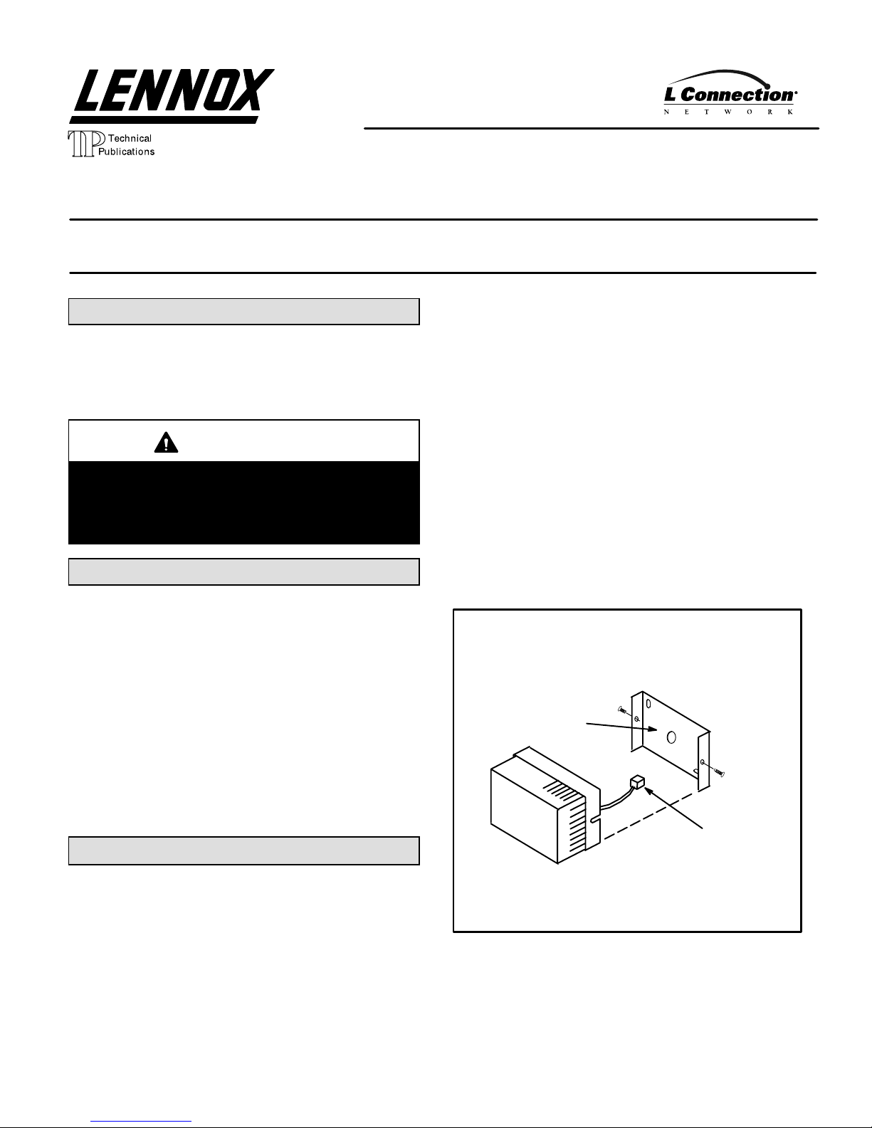
2− Remove sensor cover and center opening in
baseplate over opening in wall. See figure 1.
3− Mark holes for screws. Remove baseplate and drill
holes.
4− Insert wall anchors (field provided) and align baseplate
over opening in wall. Pull wiring through opening in
baseplate. Secure baseplate to wall with screws.
FIGURE 2
WIRING
CONNECTOR
SENSOR
BASEPLATE
5− Connect the shielded cable to sensor terminal block.
6− Replace sensor cover and tighten side screws to
secure in place.
Page 2
7− Connect sensor to any available input (T1, T2, T3,
T4) on P187 Building Controller terminal block.
Connect the shield drain wire to the input common as
shown in figure 2.
Make note of which inputs are used and refer to Unit
Controller (UC) Software manual to configure
override outputs and alarms.
The temperature will be displayed on the NCP. Refer
to the NCP Software manual to enter a description of
the temperature input.
FIGURE 2
WIRE INDOOR SENSOR TO P187 ON BC1
T1
T2
T3
T4
P187
1
2
3
4
5
6
7
8
1
Building
Controller
BC
Temperature
Sensors
Sensor Check
Check the temperature displayed on the NCP. If the
temperature is incorrect, disconnect the sensor from the
BC and measure the resistance. The resistance should
correspond to the temperature as follows:
Important: The sensor must be disconnected
from the BC before measuring resistance.
°F Resistance
−40 335,671
−20 164,959
0 85,323
20 46,218
30 34,566
40 26,106
50 19,904
60 15,313
70 11,884
80 9,298
90 7,332
100 5,826
120 3,756
130 3,047
All values are +/− 2%.
The operating range of each input is −40°F to 130°F
(−22°C to 54°C).

Other Lennox Accessories manuals

Lennox 59M05 User manual

Lennox

Lennox 59M05 User manual

Lennox 47W36 User manual

Lennox

Lennox 47W36 User manual

Lennox CS User manual

Lennox

Lennox CS User manual

Lennox LCH Series User manual

Lennox

Lennox LCH Series User manual

Lennox 21L07 User manual

Lennox

Lennox 21L07 User manual

Lennox LGH420 User manual

Lennox

Lennox LGH420 User manual

Popular Accessories manuals by other brands

Mobius M9 SORTER user guide

Mobius

Mobius M9 SORTER user guide

Reer ULISSE UPC Use and maintenance

Reer

Reer ULISSE UPC Use and maintenance

AEMC MN114 user manual

AEMC

AEMC MN114 user manual

PRESONUS StudioLive 24 owner's manual

PRESONUS

PRESONUS StudioLive 24 owner's manual

Hytronik HMW25 Installation and instruction manual

Hytronik

Hytronik HMW25 Installation and instruction manual

PCB Piezotronics 208C04 Installation and operating manual

PCB Piezotronics

PCB Piezotronics 208C04 Installation and operating manual

Carel tERA Connect Box 2G/3G Assembly and installation

Carel

Carel tERA Connect Box 2G/3G Assembly and installation

Philips Sonicare 7000 manual

Philips

Philips Sonicare 7000 manual

Honeywell DC515SP2 Getting started

Honeywell

Honeywell DC515SP2 Getting started

wtw IFL 700 IQ operating manual

wtw

wtw IFL 700 IQ operating manual

Invisible systems QC0161 installation manual

Invisible systems

Invisible systems QC0161 installation manual

Rice Lake IQ 700IS installation manual

Rice Lake

Rice Lake IQ 700IS installation manual

ZooZ ZSE40 user manual

ZooZ

ZooZ ZSE40 user manual

Star ECONO EC-CCY Operation manual

Star

Star ECONO EC-CCY Operation manual

Diamond Kinetics PitchTracker Baseball user guide

Diamond Kinetics

Diamond Kinetics PitchTracker Baseball user guide

AVZ Twins Piazzola Installation instruction

AVZ

AVZ Twins Piazzola Installation instruction

La Crosse Technology TX-63U-IT instruction manual

La Crosse Technology

La Crosse Technology TX-63U-IT instruction manual

STI SR125SMS operating instructions

STI

STI SR125SMS operating instructions

manuals.online logo
manuals.online logoBrands
  • About & Mission
  • Contact us
  • Privacy Policy
  • Terms and Conditions

Copyright 2025 Manuals.Online. All Rights Reserved.