manuals.online logo
Brands
  1. Home
  2. •
  3. Brands
  4. •
  5. Lennox
  6. •
  7. Recording Equipment
  8. •
  9. Lennox Humiditrol User manual

Lennox Humiditrol User manual

1
Humiditrol®Interface Kit for
Harmony III Zoning System
507944-01
6/2019
Supersedes 505,337M
Table of Contents
Shipping and Packing List......................................................1
General Information ................................................................1
Transformer......................................................................... 1
Freeze-stats (for indoor coil) ............................................... 1
Discharge Air Temperature Sensor (DATS) (88K38)........... 1
Outdoor Air Temperature Sensor (OATS) (X2658).............. 2
Installing the Dehumidication Interface Control ................2
Relays ................................................................................. 2
Three-Pole Selector Switch................................................. 2
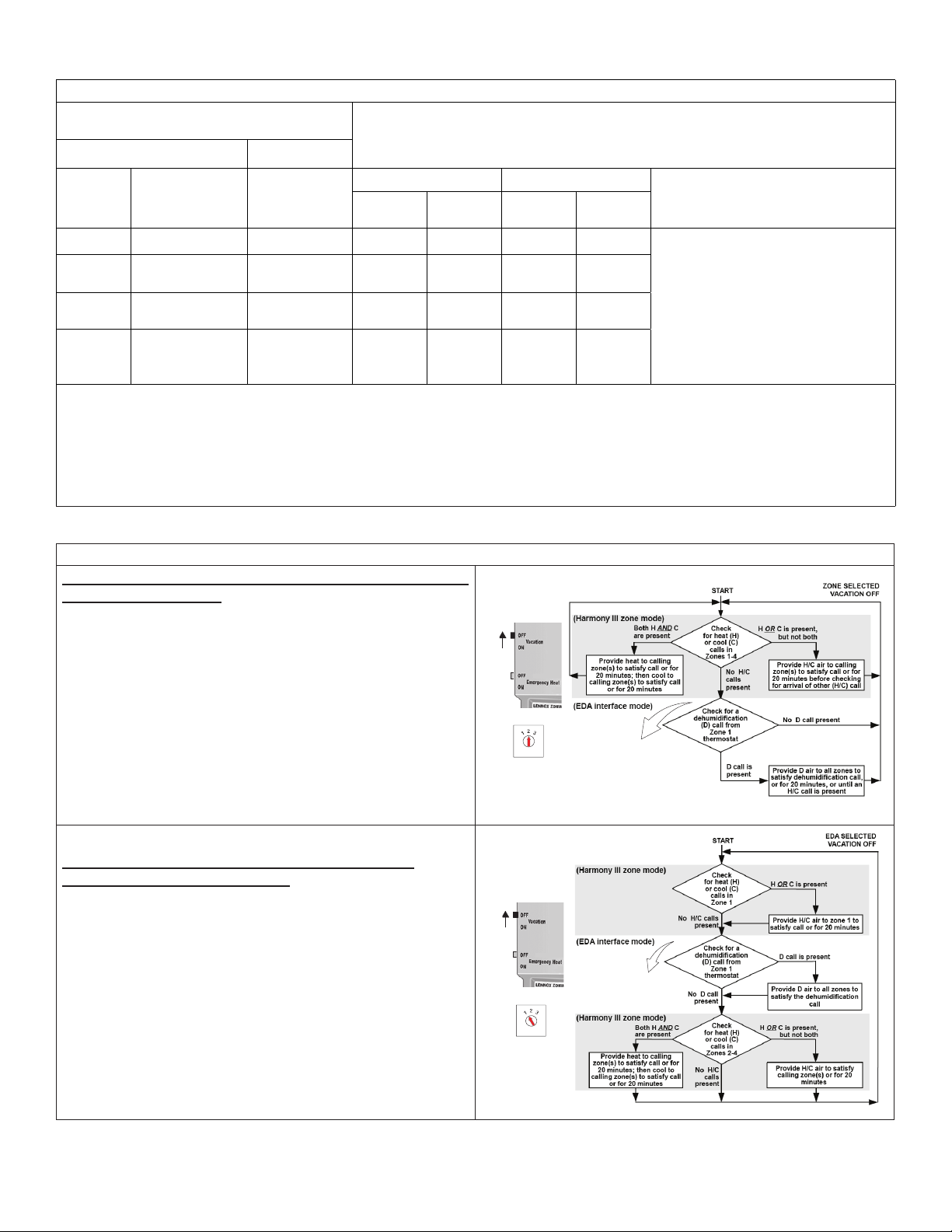
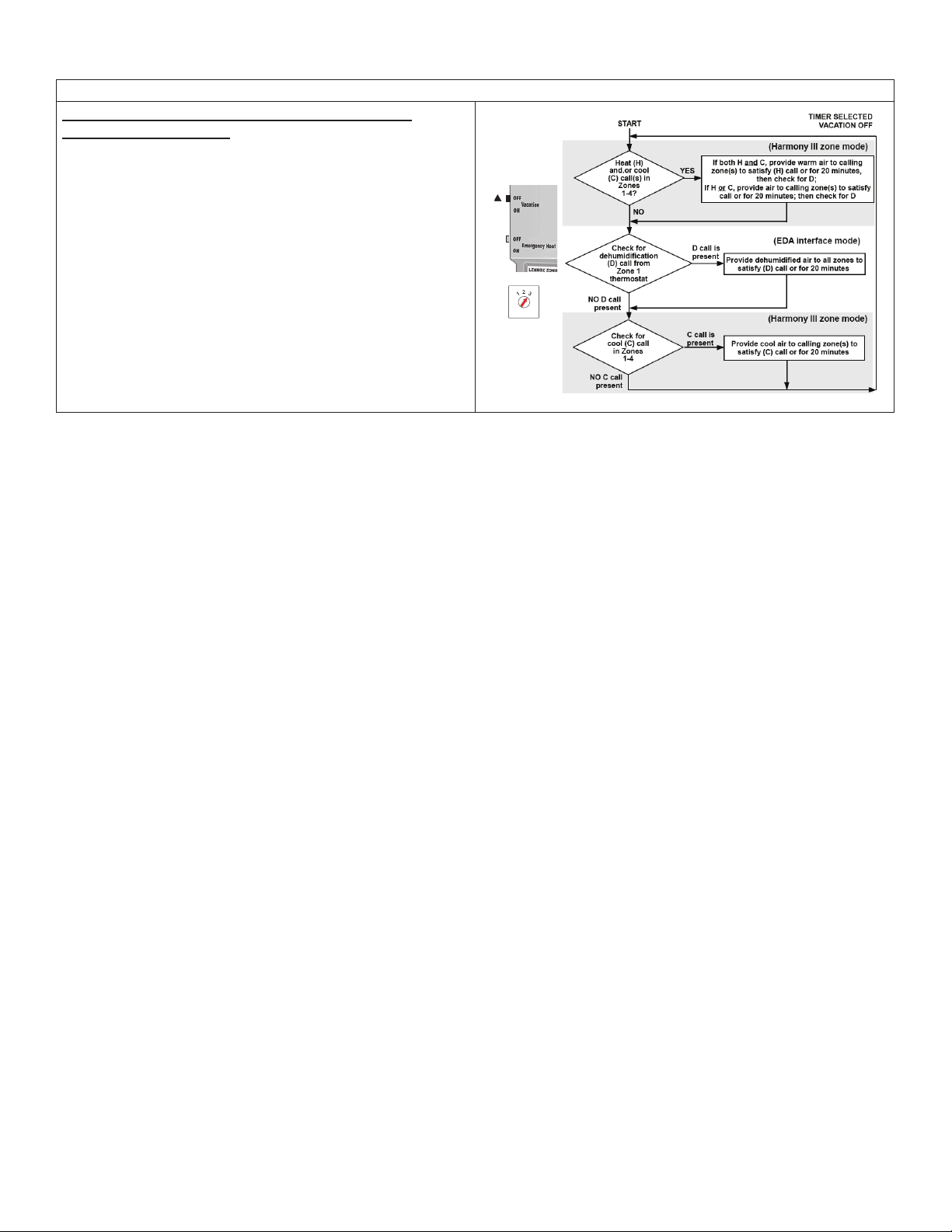
Humiditrol / Zone Control Demand Priorities and Flow
Diagrams............................................................................. 2
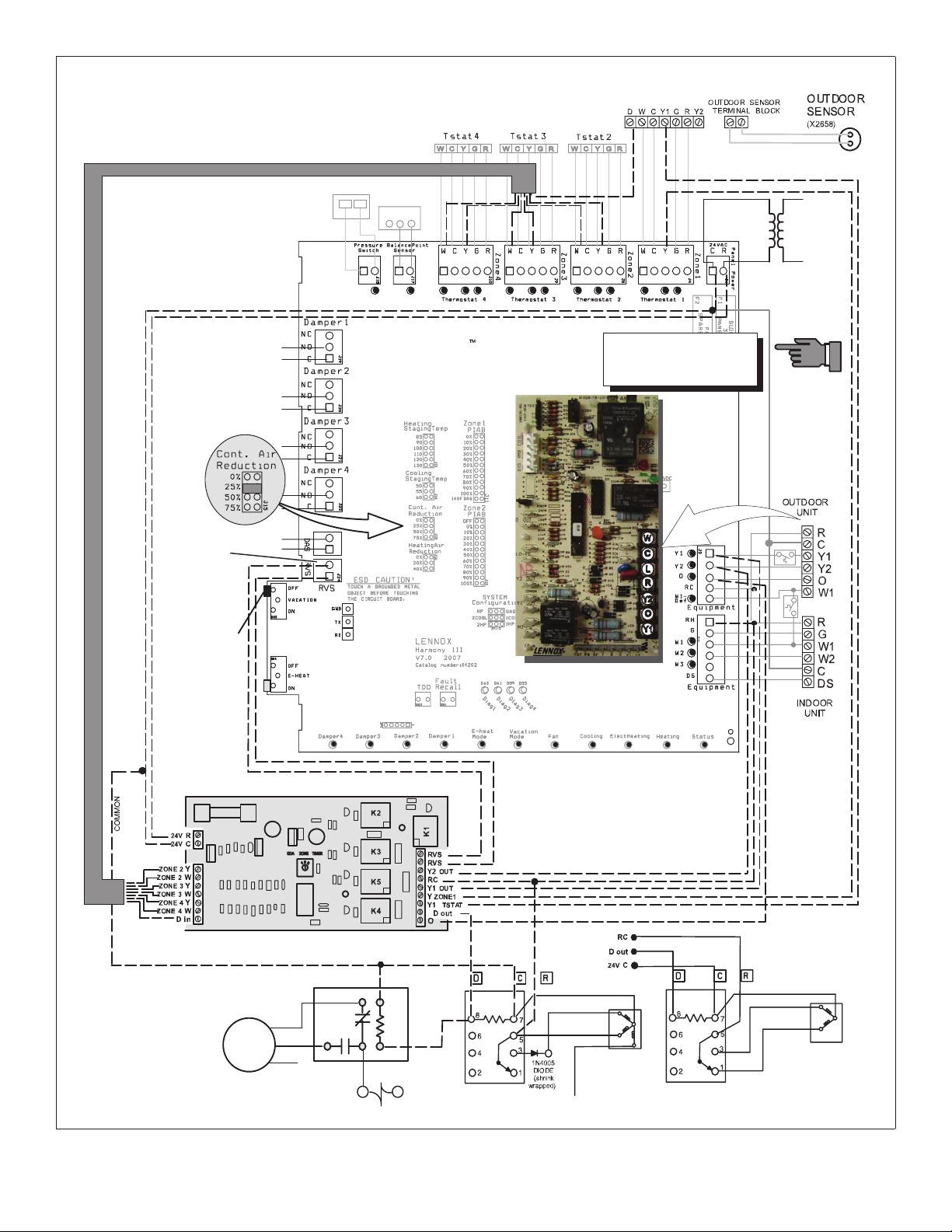
Humiditrol / Zone Control Wiring......................................... 2
Zone Control Transformer Phasing .......................................7
Important Installer Information ..............................................7
Enable and Adjust Humiditrol ................................................8
Enabling or Disabling Dehumidication (User Settings)...... 8
Adjusting Dehumidication.................................................. 8
Homeowner Vacation Setup and Reset.................................8
Shipping and Packing List
Package 1 of 1 contains:
Item Quantity
Humiditrol Interface Control 1
Installation Instruction 1
Wiring Diagram (535,851W) 1
CAUTION
Danger of sharp metallic edges.
Can cause injury. Take care when servicing unit to avoid
accidental contact with sharp edges.
General Information
IMPORTANT
This dehumidication kit is for use with ONLY Harmony
III™ zoning system. A copy of these instructions must be
left with the homeowner.
CONTROLS
KITS AND ACCESSORIES
Humiditrol®Interface Kit (39W67) Installation Instruction
Use this kit to add the Humiditrol® (enhanced dehumidication
accessory) to a Harmony III™ zoning system. This
installation instruction also provide basic information for
service technician and homeowners on all the operational
system settings.
The zone 1 master room thermostat must have a
dehumidication output that is a “reverse logic” type, i.e., it
outputs a 24 VAC signal when there is NO dehumidication
demand and outputs 0 volts when there is a dehumidication
demand.
NOTE: See the Harmony III™ zoning system Installation
Instruction for details on compatible Lennox
thermostats.
Transformer
Five (5) volt−amps (VA) are required for the Humiditrol
interface control. The relays on the interface board must be
powered by the same system transformer that provides 24
VAC power to the zone control, thermostats, zone dampers
and DS output signal to the air handler/furnace. The air
handler/furnace transformer provides 24VAC through the
zone control equipment relays and interface board relay
contacts to cycle heating or cooling demands to the out-
door unit, the indoor unit, and the Humiditrol. See Harmony
III zoning system Installation Instructions for transformer list.
freeze-sTaTs (for indoor coil)
If the minimum air requirement for the Humiditrol system is
less than 350 CFM per ton, it is recommended that a freeze-
stat be installed on the indoor coil to prevent icing of the coil.
Lennox Freezestats are:
• 93G35 [3/8”] (Opens at 29ºF and closes at 58ºF)
• 50A93 [5/8”]) (Opens at 36ºF and closes at 58ºF)
The freeze-stat senses when suction line temperature falls
below its setpoint and cycles the compressor off; it opens at
29ºF and closes at 58ºF. Install the freeze-stat on an out- let
tube of the evaporator coil. See gure 1.
discharge air TemperaTure sensor (daTs) (88K38)
Locate the Discharge Air Sensor (DATS) on the outlet side
of the Humiditrol. See “Figure 1. Discharge Air Sensor and
Freezestat Installations” on page 2.
©2019 Lennox Industries Inc.
Dallas, Texas, US
A
2
INDOOR
UNIT
AIR
FLOW
FASTEN THE PROBE
BRACKET TO THE
PLENUM WITH TWO
SELF- TAPPING SHEET
METAL SCREWS.
PLENUM
CONNECT WIRES
TO DAS ON ZONE
CONTROL BOARD
EDA
5−1/2"
CLIP FREEZE−STAT
ON OUTLET TUBE
LOCATE SENSOR APPROX.
10" FROM EDA COIL
SENSOR TIP SHOULD BE
APPROX. CENTERED IN PLENUM
10"
Figure 1. Discharge Air Sensor and Freezestat
Installations
ouTdoor air TemperaTure sensor (oaTs) (X2658)
For proper operation of Humiditrol applications, an outdoor
air temperature sensor MUST be installed!
Installing the Dehumidication Interface Control
Use the interface control unit’s enclosure back-plate as a
template for locating mounting holes. Attach the interface
unit near the Harmony III™ zoning system control. Wire the
system according to wiring diagram, see “Figure 4. Zone
Control for Humiditrol Operations” on page 5.
relays
• K1 closes contacts and puts the zone control in vacation
mode when there is a call for dehumidication (RVS to
RVS).
• K2 closes contacts to send a Y2 signal to the outdoor unit
when there is a dehumidication call (RC to Y2).
• K3 closes contacts to send a Y1 signal to the outdoor unit
when there is a dehumidication call (RC to Y1).
• K4 opens contacts to remove 24VAC signal to Humiditrol
and outdoor unit Humiditrol fan relay. This will energize the
Humiditrol and slow the outdoor fan motor down to a lower
RPM (RC to D).
• K5 opens contacts to remove the Y1 thermostat signal to
the Zone 1 input on the zone control (Y1 thermostat to Y1
zone).
RELAY
K4
RELAY
K5
RELAY
K1
RELAY
K2
RELAY
K3
3-POSITION SELECTOR
SWITCH
Figure 2. Humiditrol Interface Three Position
Selector Switch
Three-pole selecTor swiTch
The three−pole selector switch is wired to toggle to three
separate operational modes, where:
1. Humiditrol (dehumidication) demand
is master of system operation, or
Humiditrol Interface
Control
Zone Timer
2. Zone (factory−default setting)
demand is master of system operation
(see “Table 1. Humiditrol Interface
Control Switch Selections (Vacation
OFF mode)” on page 3), or
3. Internal non-adjustable TIMER will cycle system
between dehumidication and heat/cool demands
every twenty minutes. (This cycling will only occur
when there is a call for both demands.)
humidiTrol / zone conTrol demand prioriTies and flow
diagrams
“Figure 3. System Flow Diagram Central Mode (Vacation
ON)” and “Table 2. System Flow Diagrams Zoning mode
(Vacation OFF)” on page 3 show the Harmony III™ zone
control system with the Humiditrol interface control and
how the Humiditrol interface control’s three-position switch
changes the priority of demands for heating and cooling and
for dehumidication.
“Table 1. Humiditrol Interface Control Switch Selections
(Vacation OFF mode)” on page 3 shows the heat,
cool, and dehumidication priorities using all the possible
scenarios of heating/cooling and dehumidication calls.
(Individual calls of any type are answered as received.)
ZONE1 Heating/Cooling Has Priority Over
Dehumidification
HUMIDITROL ENABLED (on zone 1 thermostat)
Vacation ON (on zone control; NO zone distribution)
A
NY POSITION selected (on EDA interface control)
NOTE − If a remote vacation switch is used, only ONE of the switches
must be ON.
See NOTE
NOTE − Te mperature must be be-
low 95ºF before the thermostat will
allow call for Dehumidification.
Figure 3. System Flow Diagram Central Mode
(Vacation ON)
humidiTrol / zone conTrol wiring
“Figure 4. Zone Control for Humiditrol Operations” on
page 5 shows how the Humiditrol interface control and
Harmony III™ zoning system control are wired for use with
the enhanced dehumidication accessory.
NOTE: The diagram shows only Humiditrol interface control
wiring. See Harmony III installation instruction for all
other zone control wiring.
3
Table 1. Humiditrol Interface Control Switch Selections (Vacation OFF mode)
Zone Room Thermostat Demand Priority Chart (Reads left to right) - Three-Pole Selector Switch (Default 2)
Combination of Room Thermostat Demands
From: Demands Served First when Humiditrol interface switch is set to:
Zone 1 Zones 2−4
Humiditrol Zone
Timer
Heat or
Cool Dehumidication Heat or Cool H/C D H/C D
√√√ √ H or C, with D present:
√ √ √√• H/C−1ST
• D−2ND
√√√ √ If H and C with D present:
√√√√ √
• H−1ST
• D−2ND
• C−3RD
NOTE: A dehumidication demand can NOT be activated on Zone 1 room thermostat until heat or cool demand is satised and the room temperature
is within the required calculated temperature range.
Harmony III − Heat and cool demands presented at the same time from different zones (opposing demands) are satised on a rst-come, rst-serve
basis. If a cooling demand reaches the Harmony III zone control board at the same time as the heating demand, heating is satised rst. If opposing
demands persist, the system will work to satisfy the current demand for a maximum of 20 minutes, then switch over and try to satisfy the opposing
demand for a maximum of 20 minutes. When either demand is satised, the system works to satisfy any other demand.
Table 2. System Flow Diagrams Zoning mode (Vacation OFF)
How the Humiditrol Interface control’s three position selector switch settings affect functional operation:
Heating/Cooling Calls for all Zones have Priority over a
Dehumidication Call
HUMIDITROL ENABLED (on zone 1 thermostat) Vacation OFF (on zone
control; zone distribution enabled) ZONE selected (on Humiditrol interface
control)
NOTE: If a remote vacation switch is used, both switches must be in
OFF position.
NOTE: Heat demand will be satised rst ONLY in the event that heat
and cool calls arrive at the same instant. If cooling is being pro-
vided, that demand will be satised rst (or until 20 minutes has
elapsed), then heat will be provided to calling zone(s).
PRIORITIES − All H/C calls must be satised before any attempt to satisfy
a Dcall is allowed. Then, a D call may be satised, or allowed to run for up
to 20 minutes, after which time the zone control checks for and satises
any new H/C calls before again attempting to satisfy D.
SEE
NOTE
NOTE − Te mperature must be be-
low 95ºF before the thermostat will
allow call for Dehumidification.
Humiditrol
Interface
Zone Timer
Dehumidication Call has Priority over Heating/
Cooling Calls from Zones 2 − 4
HUMIDITROL ENABLED (on zone 1 thermostat)
• Vacation OFF (on zone control; zone distribution enabled)
• Humiditrol selected (on Humiditrol interface control)
NOTE: If a remote vacation switch is used, both switches must be in
OFF position.
NOTE: When both thermostat (Hand/or C) and dehumidication (D)
calls are present, the H/C call being addressed will run for 20
minutes, then D will be run until satised.
PRIORITIES − A zone 1 call for Hor C is allowed to run until satised be-
fore checking and addressing a dehumidication call. Then, a D call MUST
be satised before ad- dressing any H/C calls.
SEE NOTE
NOTE − Te mperature must
be below 95ºF before the
thermostat will allow call for
Dehumidification.
Humiditrol
Interface
Zone Timer
4
Table 2. System Flow Diagrams Zoning mode (Vacation OFF)
How the Humiditrol Interface control’s three position selector switch settings affect functional operation:
Timer Alternates Between Heating/Cooling and
Dehumidication Calls
HUMIDITROL ENABLED (on zone 1 thermostat) Vacation OFF (on zone
control; zone distribution enabled) TIMER Selected (on Humiditrol inter-
face control)
NOTE: If a remote vacation switch is used, both switches must be in
OFF position.
NOTE: If the system is addressing zones calling for both H and Cwhen
a D call arrives, the H call will be allowed to run for 20 minutes,
then switch to dehumidication for 20 minutes before addressing
a Ccall.
PRIORITIES − The timed interval mode accepts and ad- dresses each
call, as received, to satisfy the call or run for up to 20 minutes, except when
multiple calls arrive simultaneously. Then, the order is 1) Hor Cthen 2)
D. If calls for all three are present (Hand Cand D), then the order is H, D
and C.
NOTE: If there is a Y1 output from the thermostat, the de- humidication
is delayed until Y1 is satised.
NOTE − Temperature must be be-
low 95ºF before the thermostat will
allow call for Dehumidification.
Humiditrol
Interface
Zone Timer
5
GREY
RED
PINK
EDA RELAY
BLACK
EDA VALVE
ACTUATOR
Remote Vacation
Switch connections
and connections for
EDA interface con-
troller
DAMPERS
1 2 3120
VAC
24
VAC
DAS
Humiditrol Interface
ZONE 1
THERMOSTAT
HARMONY IIIZONE CONTROL
Black
Red
BE SURE COMMON WIRES
ARE JOINED TOGETHER &
HAVE CORRECT PHASING!
See figure 6.
Black
Purple
NOT USED;
TAPED OFF
4−WIRE
MODELS
Purple
Purple
VIOLET
ORANGE
EDA VALVE
ACTUATOR
EDA RELAY
RED
3−WIRE
MODELS
Black
Red
B4
FAN
Blue
Yellow
Black
K1
Yellow
2
75
Continuous Air Re-
duction Jumper
(See note 3)
Vacation Switch
(See note 2)
Note 1. This diagram shows wiring in addition to Harmony III zone con-
trol wiring; see zone control manual for all other wiring.
Note 2. If a remote vacation switch is used, it is recommended that the remote
switch be located near the ZONE 1 thermostat and NOT located near any
other household switches. The switch on this board should then be switched
OFF permanently.
Note 3. Be sure continuous air reduction jumper is set on 25%.
See Zone Control Transformer
Phasing on page 7.
Figure 4. Zone Control for Humiditrol Operations
6
GREY
RED
PINK
EDA RELAY
NOT USED;
TAPED OFF
BLACK
Remote Vacation
Switch connections
and connections for
EDA interface con-
troller
DAMPERS
1 2 3120
VAC
24
VAC
DAS
Humiditrol Interface
ZONE 1
THERMOSTAT
HARMONY IIIZONE CONTROL
Black
Red
BE SURE COMMON WIRES
ARE JOINED TOGETHER &
HAVE CORRECT PHASING!
Black
EDA VALVE
ACTUATOR
4−WIRE
MODELS
Purple
Purple
VIOLET
ORANGE
EDA VALVE
ACTUATOR
EDA RELAY
RED
3−WIRE
MODELS
Black
Red
Continuous Air Re-
duction Jumper
(See note 3)
Vacation Switch
(See note 2)
Note 1. This diagram shows wiring in addition to Harmony III
zone control wiring; see zone control manual for all other wiring.
Note 2. If a remote vacation switch is used, it is recommended that
the remote switch be located near the ZONE 1 thermostat and
NOT located near any other household switches. The switch on
this board should then be switched OFF permanently.
Note 3. Be sure continuous air reduction jumper is set on 25%.
Clip W1 Jumper
for Humiditrol
(EDA) application
Trace cut for
Humiditrol (EDA)
application
Trace
intact
EARLY
CONTROL
CURRENT
CONTROL
See Zone Control Transformer
Phasing on page 7.
Figure 5. Zone Control for Humiditrol Operations (Lennox Communicating Controls - 24VAC)
7
CHECK VOLTAGE BEFORE CONNECTING ZONE CONTROL TRANS-
FORMER LEADS TO THE ZONE CONTROL PANEL CONNECTIONS
Figure 6. Conrming Transformer Phasing (Polarity) is Correct
Zone Control Transformer Phasing
Using two transformers on a single system when the
Harmony III zoning system is connected to a system that
has its own transformer, the phasing (or polarity) of the air
handler transformer to the zone control’s add−on trans-
former is extremely IMPORTANT because the zone control
transformer powers the DS circuit within the zone control
and then connects to the air handler DS circuit.
The only two transformers that need correct phasing with their
commons connected are the zone control and air handler
transformers. Check the phasing prior to connecting the
zone control transformer zone control panel’s connections.
The zone control transformer primary should be the same
source as the air handler to keep it uncomplicated. Use a
230 VAC primary transformer with 230 VAC coil/blowers and
use a 115 VAC transformer with furnaces.
1. Connect the zone control transformer primary to the
air handler voltage source (see “Figure 6. Conrming
Transformer Phasing (Polarity) is Correct”).
2. Do not connect the zone control transformer secondary
to the zone control panel at this time.
3. Connect air handler secondary common to the assumed
zone control transformer common.
4. Measure voltage between air handler Rand unconnected
zone control transformer secondary lead (see Figure 6):
• If 0 volts (A, Figure 6) then polarity is correct; con-
nect the leads to zone control Cand Ras shown.
• If 48 volts (B, Figure 6) then polarity is reversed;
swap leads as shown and conrm 0 volts (C, gure
6); connect the leads to zone control Cand Ras
shown.
5. With the correct polarity determined, connect Cwire to
zone control 24VAC Cterminal and Rwire to Rterminal.
Important Installer Information
If a remote vacation switch is used and locate it near the
Zone 1 thermostat. Label the switch (eld-provided) and
instruct user on proper operation:
• Toggle up − ZONING ON (vacation off)
• Toggle down − VACATION ON (zoning off)
NOTE: DO NOT locate the remote vacation switch next
to other house switches or anywhere it may be
inadvertently switched on or off.
Before leaving the site, check the following and conrm that
all applicable items have been addressed:
Outdoor sensor installed and connected to Zone
1 thermostat Humiditrol operation requires use of
an outdoor sensor (see “Outdoor Air Temperature
Sensor (OATS) (X2658)” on page 2). If sensor
is not connected and Humiditrol is enabled,
“OUTDOOR SENSOR REQUIRED” is displayed in
the information display.
Remote Vacation Switch installed near Zone 1
thermostat.
Remote Vacation Switch clearly labeled.
Remote Vacation Switch to Zoning ON (vacation off).
Vacation Switch on the Harmony III™ zoning system
control OFF.
Continuous Air Reduction jumper on Harmony III™
zoning system control board set to 25%.
Humiditrol enabled.
Humiditrol Interface Control Switch set.
User understands how to control system, how to
setup for vacation, how to restore zoning after
vacation.
8
Enable and Adjust Humiditrol
enabling or disabling dehumidificaTion (user seTTings)
If dehumidication is NOT needed during vacation you can
switch off dehumidication as follows:
CS7500
Go to Menu > press and hold settings > select conrm >
humidity settings > dehumidify and select off.
iComfort M30
Go to Menu > settings > humidity control and select off
or dehumidify.
iComfort E30
Go to Menu > settings > humidity and select off or
dehumidify.
adjusTing dehumidificaTion
Dehumidication set point can be adjusted from the user
settings screen under either humidity or humidity control.
Typical the adjust range is 40% to 60%. Factory default is
typically 55%.
For detail instructions on Humiditrol adjustments and other
settings, refer to the thermostat’s installation and setup
guide.
Homeowner Vacation Setup and Reset
Switching the Vacation Switch on forces the system to act as
a conventional central air conditioning and heating system.
All zones will be controlled by zone 1 room thermostat and
all zone dampers will remain in the open position.
While vacation mode is ON, and if there is no heating or cooling
call demand from Zone 1 and there is a dehumidication
demand, those demands will continue to be served without
further operator settings.
REMOTE
VACATION
SWITCH
HARMONY III
VACATION
SWITCH
OR
Figure 7. Vacation Switch

This manual suits for next models

1

Other Lennox Recording Equipment manuals

Lennox 10T50 Assembly instructions

Lennox

Lennox 10T50 Assembly instructions

Lennox 10T50 Assembly instructions

Lennox

Lennox 10T50 Assembly instructions

Lennox 22X18 Assembly instructions

Lennox

Lennox 22X18 Assembly instructions

Popular Recording Equipment manuals by other brands

Nagra LB Brochure & specs

Nagra

Nagra LB Brochure & specs

Fitzgrevye MUWZ manual

Fitzgrevye

Fitzgrevye MUWZ manual

Eventide TimeFactor user guide

Eventide

Eventide TimeFactor user guide

Crestron C2N-UNI8IO Installation & operation guide

Crestron

Crestron C2N-UNI8IO Installation & operation guide

Yamaha DSR1 Advanced operation manual

Yamaha

Yamaha DSR1 Advanced operation manual

PXM PX359 user manual

PXM

PXM PX359 user manual

Shure Microphone Level Tone Generator A15TG user guide

Shure

Shure Microphone Level Tone Generator A15TG user guide

Pointmaker CPN 5800 user guide

Pointmaker

Pointmaker CPN 5800 user guide

AMX AXC-DTMF Plus Dimensional drawing

AMX

AMX AXC-DTMF Plus Dimensional drawing

Midas DL251 Operator's manual

Midas

Midas DL251 Operator's manual

AAton Cantar-X user manual

AAton

AAton Cantar-X user manual

AND FG-27CWPJA instruction manual

AND

AND FG-27CWPJA instruction manual

Chauvet DJ Obey 6 Quick reference guide

Chauvet DJ

Chauvet DJ Obey 6 Quick reference guide

Yamaha MOTIF RACK Music System Data list

Yamaha

Yamaha MOTIF RACK Music System Data list

Frontier AlphaTrack Description

Frontier

Frontier AlphaTrack Description

M2SYNTH BR VCF 114 Assembly instructions

M2SYNTH

M2SYNTH BR VCF 114 Assembly instructions

Yamaha ProR3 owner's manual

Yamaha

Yamaha ProR3 owner's manual

Kroeplin C - Series user manual

Kroeplin

Kroeplin C - Series user manual

manuals.online logo
manuals.online logoBrands
  • About & Mission
  • Contact us
  • Privacy Policy
  • Terms and Conditions

Copyright 2025 Manuals.Online. All Rights Reserved.