Vidicode V-Tap VoIP User manual

V-Tap VoIP Manual EN v2.7 Oct 2018 © 2017-2018 Vidicode 1
V-Tap VoIP
Manual
v2.7

V-Tap VoIP Manual EN v2.7 Oct 2018 © 2017-2018 Vidicode 2
Contents
1Introduction....................................................................4
2Getting started...............................................................5
2.1 Hardware installation.......................................................5
2.1.1 Connection at Home .............................................................. 6
2.1.2 Connection at the Office........................................................ 6
2.2 Software installation ........................................................7
2.2.1 Call Recorder Apresa.............................................................. 7
2.2.2 Call Recorder VoIP on the PC ................................................. 8
2.3 Checklist for Tunnel connection ......................................9
3Web interface and Settings .........................................10
3.1 IP address.........................................................................10
3.2 Web interface..................................................................11
3.3 Settings............................................................................14
3.3.1 General network settings .................................................... 14
3.3.2 Tunnel settings..................................................................... 16
3.3.3 FTP & Web settings .............................................................. 19
3.3.4 Telnet setting ....................................................................... 20
3.3.5 NTP settings.......................................................................... 21
3.3.6 Date and Time settings........................................................ 22
3.3.7 Advanced Settings ............................................................... 22
3.3.8 Button Mode setting............................................................ 23
3.3.9 SD Card settings ................................................................... 24
3.3.10 Port settings ......................................................................... 27
3.3.11 Special network settings ..................................................... 28
3.3.12 App Special Flags ................................................................. 29
3.3.13 Licenses & Versions .............................................................. 30

V-Tap VoIP Manual EN v2.7 Oct 2018 © 2017-2018 Vidicode 3
4LED’s .............................................................................31
4.1 Red Error LED ..................................................................31
4.2 Green Link LED................................................................32
4.3 Blue Data LED..................................................................33
4.4 Amber SD-Power LED .....................................................33
5Button functions ..........................................................34
5.1 Start & Stop recording....................................................34
5.2Remove SD Card safely ..................................................34
5.3 Enable DHCP temporary.................................................35
5.4 Show IP address ..............................................................35
5.5 Factory settings...............................................................36
5.6 Default IP address...........................................................36
5.7 Firmware update ............................................................37
6Connection schemes ....................................................38
6.1 Tunnel function...............................................................38
6.2 Split Ports 34 ...................................................................39
6.3 Split Port 4 .......................................................................39
6.4 Split Ports 34 & Split Port 4 (SPAN mode)..................40
6.5 Mirror to Port 4 ...............................................................41
6.6 Mirror to Port 3 ...............................................................41
7Technical Specifications ...............................................42
8Revision History ...........................................................43
9Acknowledgements .....................................................44
9.1 Privacy..............................................................................44
9.2 Liability ............................................................................44

V-Tap VoIP Manual EN v2.7 Oct 2018 © 2017-2018 Vidicode 4
1Introduction
The V-Tap VoIP is a hardware and software solution for the recording of
telephone calls that are transported over an IP network. The supplied
hardware unit sniffs the digital data coming from external IP telephones
and can copy the data back to the network or stores the data directly
onto an SD card. In both cases the data is wrapped into a special Tunnel-
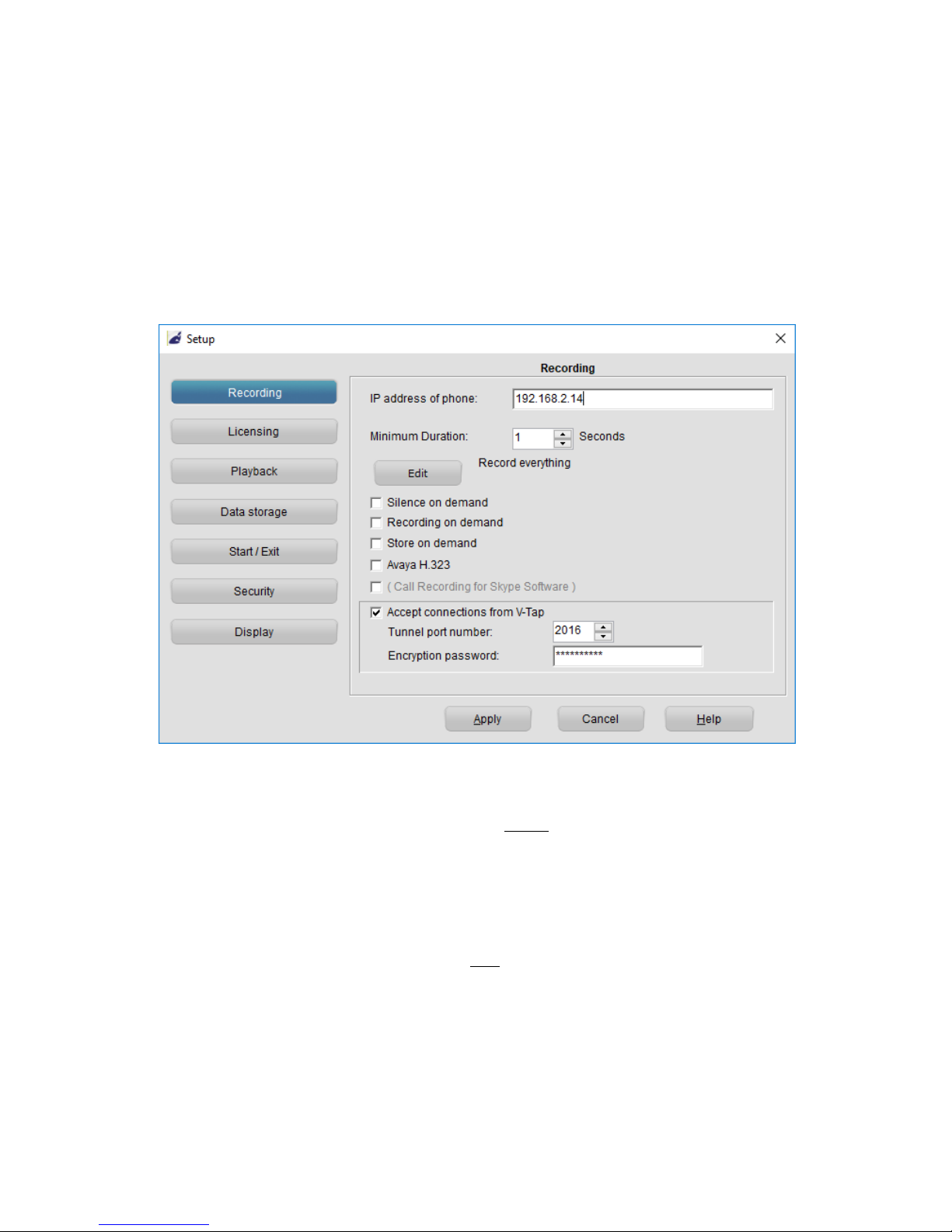
format that can be received by the Call Recorder Apresa (running on
Linux) or by the Call Recorder VoIP software (running on a Windows PC).
The external Apresa recorder or CR-VoIP software can both interpret the
Tunnel-format and make playable audio files from it, together with the
original date, time and call number information (meta data).
The build-in switch function allows 4 Ethernet connections (100 Mbps).
This makes it possible to connect 3 external IP phones and one
connection to the network. For a desktop solution, it is also possible to
connect a PC or other network peripherals.
An IP phone can also be a Softphone running on a PC. This is achieved
by simply wiring the PC’s network through the V-Tap VoIP switch.
In the case that no SD card is inserted, the sniffed data is sent life over
the network to the Apresa recorder or CR-VoIP software.
With an SD card inserted, the sniffed data is stored as files on the card.
Depending on whether a Tunnel has been defined or not, the files are
sent over the network or can be read later by the CR-VoIP software.
By using the SD card (FAT32 formatted), the V-Tap VoIP can operate
completely stand alone and can store data for months or even years,
depending on the capacity of the card.
The internal settings of the V-Tap VoIP can be accessed through a web
interface by any browser.
The V-Tap VoIP is a member of a family of compatible products that can
be used to create all sorts of Call Recording solutions. There are V-Taps
for Analog and ISDN telephony, there is an App for mobile recording
and all these products communicate with the Apresa Corporate
recording solution or Apresa cloud-based recording.
NOTE: The V-Tap VoIP needs to be powered through USB, otherwise
the device cannot record from external IP phones.

V-Tap VoIP Manual EN v2.7 Oct 2018 © 2017-2018 Vidicode 5
2Getting started
2.1 Hardware installation
The V-Tap VoIP is easy to setup. The following steps are involved:
•Connect the local network to the V-Tap VoIP.
•Connect the IP phone(s) or PC(s) to the V-Tap VoIP.
•Connect the USB to the V-Tap VoIP for power.
•Optionally insert an SD card.
•Access the settings in the web interface by using a browser.
Any LAN port can be used to connect the external network and the IP
phones. Different configurations are also possible, see Port settings.
For more schemes see the next page and chapter Connection schemes.
NOTE: Ports PHONE2 and PHONE3 are suitable only to connect a Power over
Ethernet (PoE) loop. The V-Tap itself does not generate PoE.

V-Tap VoIP Manual EN v2.7 Oct 2018 © 2017-2018 Vidicode 6
2.1.1 Connection at Home
2.1.2 Connection at the Office

V-Tap VoIP Manual EN v2.7 Oct 2018 © 2017-2018 Vidicode 7
2.2 Software installation
External software is needed to extract the recorded calls from the
Tunnel data that is produced by the V-Tap VoIP. Also, when the data is
first stored on an SD card, external software is needed to interpret this
data from the card, especially when the data is encrypted.
The Tunnel data stream, coming directly from the V-Tap, can be send to
the Call Recorder Apresa or the Call Recorder VoIP software.
NOTE:
The V-Tap needs at least one Apresa or PC upload-channel license key
before the Apresa or CR-VoIP software can record your calls. Recording
multiple calls simultaneously need more upload-licenses.
2.2.1 Call Recorder Apresa
The Call Recorder Apresa is recorder software running on the Linux
operating system. The Apresa can receive Tunnel data from the V-Tap,
convert this data into audio files and store the files into its own
database.
The Apresa can receive multiple data streams from many V-Tap units
simultaneously. In that case the recordings of different locations are
centrally stored in one database.
To setup the Apresa to act as a Tunnel server for a V-Tap, go to
System settings, Network tab and enable “V-Tap” as is shown below:
NOTE1: Apresa’s IP address is the “Tunnel Server Address” in the V-Tap.
NOTE2: Be sure the Encryption password is the same as in the V-Tap unit.

V-Tap VoIP Manual EN v2.7 Oct 2018 © 2017-2018 Vidicode 8
2.2.2 Call Recorder VoIP on the PC
The Call Recorder VoIP software for the PC can also receive Tunnel data
from the V-Tap VoIP, convert this data into audio files and store the files
into its own database. The CR-VoIP software can also receive multiple
data streams from different V-Tap units simultaneously.
To setup the CR-VoIP software to accept connections from a V-Tap, go to
Options, Setup, Recording tab and enable as is shown below:
NOTE1: The PC’s IP address is the “Tunnel Server Address” in the V-Tap.
NOTE2: Be sure that the PC’s firewall is open for TCP port 2016, the
default “Tunnel Destination Port” in the V-Tap unit.
NOTE3: Be sure the Encryption password is the same as the
“Tunnel Encryption Password” in the V-Tap unit.
NOTE4: The CR-VoIP software does not need licenses to receive from
the V-Tap unit.
The Call Recorder VoIP software for the PC has its own manual and is
therefore further not described in this manual.

V-Tap VoIP Manual EN v2.7 Oct 2018 © 2017-2018 Vidicode 9
2.3 Checklist for Tunnel connection
A connection between V-Tap and Apresa or PC software is needed to get the
recorded data automatically into a user accessible database.
The following checklist can be used to setup this Tunnel connection:
1) Install the Hardware and be sure that the VoIP data passes the V-Tap.
2) Install the Apresa or PC Software and enable V-Tap connections.
3) Assign an IP address to the V-Tap and open the Settings page.
4) The “Tunnel Server Address”must be filled in with the IP address or
name of the Apresa recorder or the PC.
5) Any firewall must be setup to let pass TCP port 2016, the default
“Tunnel Destination Port”.
6) The Tunnel connection to the Apresa or PC software is stable when the
GREEN LED is steady, not blinking!
7) For first tests, better turn off “Tunnel Data Encryption”. Otherwise, be
sure that the Encryption password is the same for both V-Tap and
Tunnel server.
8) The V-Tap stores only VoIP data that passes the “Tunnel TCP Port Filter”.
In case of an unknown VoIP port or for test, this filter can be set to zero
to store all network traffic.
9) When data is stored during a call then the BLUE LED blinks.
10) To see if the Apresa or PC receives something from the V-Tap, it is
possible to make a network trace for test purposes.
On the PC go to menu Action and select ‘Network trace’. The
'tunneltrace.pcap' file can be read afterwards with Wireshark.
11) The SD card in the V-Tap should contain “.TUN” files.
The SD card can be read by the PC software in menu File and ‘Import
from V-Tap’.

V-Tap VoIP Manual EN v2.7 Oct 2018 © 2017-2018 Vidicode 10
3Web interface and Settings
The first step to access the web interface of the V-Tap VoIP, is to connect
a network cable to any of the 4 ports on the unit. The other side of the
cable can be connected to a LAN or directly to a PC. There is no need to
use a cross-cable.
Then any web browser can be used to access the web interface of the V-
Tap VoIP.
3.1 IP address
By default, the V-Tap unit listens to the IP address 192.168.55.66 and
DHCP is disabled. This IP address can be entered directly in the address
bar of your browser, only when your PC has an IP address that lies in the
same range as the IP address of the V-Tap. The IP address of your PC
must therefore lie in the range 192.168.55.0 till 192.168.55.255 and the
IP mask should be 255.255.255.0.
Default IP address: 192.168.55.66
Default User name: admin
Default Password: admin
DHCP can be enabled temporary by pressing the button for 1 second.
The LED’s will flash shortly as soon as an IP address is obtained and the
V-Tap is then reachable on that address.
See also Enable DHCP temporary and Show IP address.
It is also possible to set a new fixed IP address or enable DHCP by using
an SD card:
Defining a fixed IP address with an SD card:
. Create a text file on your PC, named “IP.TXT”.
. The first line in this file must hold the IP address.
. The second line is optional and can hold the IP mask.
. Copy “IP.TXT”to the root directory of an SD card.
. Insert the SD card into the V-Tap unit.
. The IP address has now changed and can be accessed.
. The file “IP.TXT” is deleted from the card by the V-Tap.
. Note: The IP address 0.0.0.0 enables DHCP on the V-Tap.

V-Tap VoIP Manual EN v2.7 Oct 2018 © 2017-2018 Vidicode 11
3.2 Web interface
Entering the IP address in your browser will show the following screen:
Now enter “admin” for the User name and “admin” for the Password,
then press the Login button and the Settings page appears (
see picture
on the next page
).
(The settings on the next page are not the default settings, but just an example.)

V-Tap VoIP Manual EN v2.7 Oct 2018 © 2017-2018 Vidicode 12
To show more settings, enable the Advanced Settings option and press
the Save & Logout button. The following page appears:

V-Tap VoIP Manual EN v2.7 Oct 2018 © 2017-2018 Vidicode 13
By pressing the Save & Logout button, the settings are sent to the V-Tap
unit. Any ongoing recording is stopped, the file on SD card is closed, and
after a few seconds the new settings are activated.

V-Tap VoIP Manual EN v2.7 Oct 2018 © 2017-2018 Vidicode 14
3.3 Settings
The settings are divided into groups that are described in the following
paragraphs.
3.3.1 General network settings
Device Name
This field can be filled in with any name you like and is used for
remote recognition of the V-Tap unit. The name is shown in the web
interface and after connecting with ftp or telnet. The name is not
used in the Tunnel protocol. The maximum length is 30 characters.
The single and double quotation marks (‘ and “) cannot be used !
DHCP Server
Default, the DHCP feature is disabled and the V-Tap unit has a fixed
IP address. When a DHCP server is available on the network, the IP
address, Subnet mask, Gateway address and DNS address are
automatically assigned. Without DHCP you must enter them
manually.
With default settings, DHCP can be enabled temporary by pressing
the button for 1 second, see Enable DHCP temporary.
Device IP Address
As part of the network, the V-Tap VoIP needs an IP address. In case a
DHCP server is used, the DHCP server will assign the V-Tap VoIP an IP
address. In case a DHCP server is not used, a static IP address must be
filled in. The default static address is “192.168.55.66”.
Subnet Mask
The subnet mask is used for so called ‘subnetting’, a way to logically
divide one network into more networks. The logical AND of the IP
address with the mask must be the same for the device and the
computer connecting to it. The default mask is “255.255.255.0”.
In case DHCP is used, the mask is automatically obtained.

V-Tap VoIP Manual EN v2.7 Oct 2018 © 2017-2018 Vidicode 15
Gateway Address
The Gateway address is used by the V-Tap VoIP unit when access
outside the local network (LAN) is required. This sort of access can be
needed by the Tunnel protocol for streaming to a remote computer
and/or by the NTP feature for obtaining the current date and time.
In case DHCP is active, the gateway is automatically obtained.
DNS Server Address
The Domain Name Service (DNS) is needed in case a name is entered
instead of an IP address for the Tunnel server and/or the NTP server.
The default DNS address 8.8.8.8 is the Google Public DNS, but the
Gateway must be defined also before this address is reachable.
In case DHCP is used, the DNS address is automatically obtained.

V-Tap VoIP Manual EN v2.7 Oct 2018 © 2017-2018 Vidicode 16
3.3.2 Tunnel settings
Tunnel Server Address
Here you fill in the IP address or host name of the Tunnel server that
is going to receive the streamed data coming from the V-Tap VoIP.
Leaving this field empty will disable the Tunnel function all together,
in which case the V-Tap unit must store its data onto an SD card.
The receiving server can be an Apresa recorder or a PC running the
Call Recorder VoIP software. In both cases, the V-Tap needs a license
to allow Tunnel data to be uploaded/streamed to the Tunnel server.
Without a license, the receiving server will discard the Tunnel data.
Tunnel Destination Port
The Tunnel protocol is based on the TCP protocol and that involves a
Destination Port and a Source Port. Both are numbers from 0 till
65535 that are included in each packet and are very important for
the receiving end of the Tunnel data. The receiving Tunnel server
must be setup to look for the same port number as is installed in this
Tunnel Destination Port.
Not all TCP port numbers are available for tunnelling, because some
are officially used by other protocols. For example, port 80 is used for
HTTP in all browsers to communicate over the World Wide Web. A
list of known port numbers can be found on the internet.
The default port number 2016 is not an official port and can be used
safely for this Tunnel protocol. The only drawback that comes by
using an unknown port is, that a firewall will block this port. For that
reason, it is important that any firewall that is passed by the Tunnel
stream must be setup right.
Firewalls must have a rule to let through TCP port 2016.
Tunnel Source Port
The Source Port also has an important role in the Tunnel protocol.
The default number 0 selects randomly a port number between
49152 and 65535. This range of port numbers is recommended by
IANA to be used for dynamic ports.

V-Tap VoIP Manual EN v2.7 Oct 2018 © 2017-2018 Vidicode 17
Once a connection has been established between the V-Tap VoIP and
the receiving Tunnel server, the chosen port number is kept active
for the duration of the communication session. When connection is
lost for some reason, a new source port is chosen for the next
connection. This ensures fast reconnection, because the TCP protocol
does not allow the same source port to be used again within a short
time. After an OS specific timeout of normally a few minutes, the
port numbers become available again for reuse.
It is therefore not recommended to select a fixed number for the
Tunnel Source Port in cases where live streaming is done without
using an SD card.
Tunnel Connect Timeout
This timeout is used when the V-Tap VoIP tries to connect to the
Tunnel server. The default 22 seconds is enough to send 4 requests. If
no reply comes from the remote side within the timeout, the V-Tap
starts trying again after a few seconds with a new source port
number (see above). Storage onto SD card just continues and is not
interrupted by any connection or disconnection of the Tunnel.
Tunnel Idle Timeout
This timeout is used to disconnect the active tunnel connection, only
when no packets are received (sniffed) anymore from the local
connected network. Default, the idle-timeout is disabled and the
tunnel stays connected forever.
The timeout is added for (yet) unknown situations where it is not
allowed to have an open TCP connection for a long time.
Tunnel Data Encryption
The data inside the Tunnel protocol is sent encrypted over the
network. The used method is AES with a 256-bit Cryptographic Key.
For privacy reasons it is advised to leave the encryption enabled.
Tunnel Encryption Password
This parameter is also used for the encryption of the Tunnel data.
The receiving side of the Tunnel data, the Apresa or CR-VoIP
software, must use the same password. Leaving the password empty
is still doing the encryption but is less secure.
The single and double quotation marks (‘ and “) cannot be used !

V-Tap VoIP Manual EN v2.7 Oct 2018 © 2017-2018 Vidicode 18
Tunnel Min Packet Size
Tunnel Packets are network packets sniffed by the V-Tap VoIP. These
are the wanted VoIP packets coming from your phone and local
network. After they passed the internal filters and match the
minimum size, they are sent with the Tunnel protocol to the server
or stored onto SD card.
The default minimum size of 60 bytes is also the minimum standard
Ethernet packet size. This means that packets of all sizes are taken.
There may be situations where it is handy to increase the size, to
minimize the overhead of stored packets. For example, when the size
is set to 61 all ACK-packets from the TCP protocol are discarded.
Tunnel TCP Port Filter
The TCP packets that are recorded (sniffed) from the local network
must pass this filter, else they are discarded.
The TCP Port Filter set to 0 (zero) disables the filter function. Then all
TCP packets are recorded, including all internet traffic, downloads
and streaming media. The receiving Tunnel server can still pick out
the VoIP calls, but on a busy local network this is not advised to do,
because the V-Tap VoIP probably gets overloaded.
Disabling the filter is therefore only useful when the V-Tap is
connected to one or more VoIP phones, not a trunk or network with
other data traffic.
To store the SIP protocol only, the port filter must be set to 5060.
The Unify HFA protocol uses port 4060. Cisco SCCP uses port 2000.
It is also possible to enter two ports; for example, “5060+2000”.
Note: This port number is also used as a filter for UDP packets.
Tunnel UDP Port Filter
UDP packets, coming from the local network, can be filtered in the
same way as TCP packets. The SIP protocol uses most of the time UDP
with a random higher port number to transport the voice data, the
so called RTP stream.
With standard SIP on the local network, this filter can be set to 0
(zero) to allow the V-Tap unit to take all UDP packets.
When the RTP stream is known, it is possible to enter a range of
ports; for example, “40000-44000”.
Note: All UDP packets that have a port number the same as the
entered “Tunnel TCP Port Filter” are also stored.

V-Tap VoIP Manual EN v2.7 Oct 2018 © 2017-2018 Vidicode 19
Tunnel Broadcast + ARP Filter
This filter sees that not too much packets are taken from the local
connected network. Many LAN’s at the office have a lot of overhead
with packets that are not relevant for recording VoIP calls.
Therefore, all Broadcast and ARP packets are standard discarded,
reducing the size of the stored Tunnel data.
Tunnel Send Start/Stop Time
Sending data via the Tunnel can be scheduled into timeframe. If lots
of data is received by the V-Tap and therefor also lots of data must
be send to the Tunnel server, it might be useful to delay the sending
to save bandwidth on the network. Sending data is done only
between the given start and stop times. The entered format can be
“HH / HH” or “HH:MM / HH:MM”. Example:
“22:30 / 08:15”, send between 10.30 in the evening and 8.15 in the morning.
3.3.3 FTP & Web settings
The V-Tap VoIP has a build in FTP (File Transfer Protocol) server that
allows you to access the internal filing system. At this moment, this is
only used for updating the firmware remotely (see chapter Update
Firmware). FTP can be disabled by setting the FTP Port to 0 (zero).
FTP & Web User name
User name to log in with FTP and the Web service. Default “admin”.
The single and double quotation marks (‘ and “) cannot be used !
FTP & Web Password
Password to log in with FTP and the Web service. Default “admin”.
The single and double quotation marks (‘ and “) cannot be used !
FTP Port Number
By default, the FTP Port is on 21 for normal FTP access.
The PC tool ‘vcUpdater’ uses FTP to update the firmware of the V-
Tap unit. This tool can be found on the Vidicode website in the menu
Service and Support > Firmware.
By setting the FTP Port to 0 (zero), FTP is disabled completely.

V-Tap VoIP Manual EN v2.7 Oct 2018 © 2017-2018 Vidicode 20
3.3.4 Telnet setting
TelNet Connection
The V-Tap VoIP can be accessed with the Telnet network protocol.
Telnet is an older protocol to access devices remotely with a simple
terminal and then perform maintenance or change settings. Telnet
also uses the TCP protocol with the fixed port number 23.
Running a Telnet client program on the PC makes it possible to
connect to the V-Tap VoIP. After connecting, the Device Name is
shown, and some debug information is constantly sent to Telnet;
Opening and closing of the Tunnel connection and, when an SD card
is used, the opening and closing of files.
Further there are two commands that can be entered with Telnet:
The command ATMENU will first ask you to enter the web access
password and then brings you in a remote maintenance menu. Once
inside the menu, the tunnel function and SD card storage are
stopped.
The menu gives the user the possibility to change the settings, reset
the SD file counters, reset to factory settings and change the clock.
Normally, there is no need to use any of these functions over Telnet.
The command ATDEBUG is a toggle to enable and disable the output
of more debug information. This is further not described in this
manual.
Other manuals for V-Tap VoIP
5
Table of contents
Other Vidicode Recording Equipment manuals

Vidicode
Vidicode V-Mic User manual

Vidicode
Vidicode V-Tap VoIP 1 User manual

Vidicode
Vidicode V-Tap ISDN PRI User manual

Vidicode
Vidicode APRESA Series User manual

Vidicode
Vidicode V-Tap VoIP User manual

Vidicode
Vidicode V-Tap ISDN PRI User manual

Vidicode
Vidicode V-Tap Analog User manual

Vidicode
Vidicode V-Tap ISDN2 User manual