2
Shipping and Packing List..............................................................................2
Indoor Transformer Requirements ................................................................2
Overview...........................................................................................................2
Equipment Interface Module Control Layout................................................3
Jumpers Pins, DIP Switch, Connections and LEDs.....................................4
Unit Type Jumper Pin Settings ................................................................................... 4
Heat Stages Jumper Pin Settings .............................................................................. 4
Heat Pump Capacity Jumper Pin Settings ................................................................. 5
Others / Vent DIP Switch Settings.............................................................................. 5
Sensor Connections ................................................................................................... 5
Dual-Fuel Terminal Connections ................................................................................ 6
Conventional Terminal Connections and Wiring Requirement ................................... 6
LED Indicators............................................................................................................ 7
Soft Disable ................................................................................................................ 7
Lennox Communicating Thermostat Commissioning (Conventional Outdoor Unit) ... 8
Operating Environment Specications .........................................................8
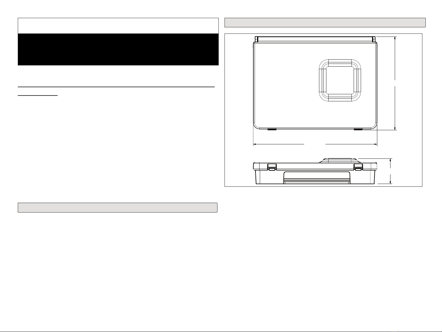
Unit Dimensions ..............................................................................................8
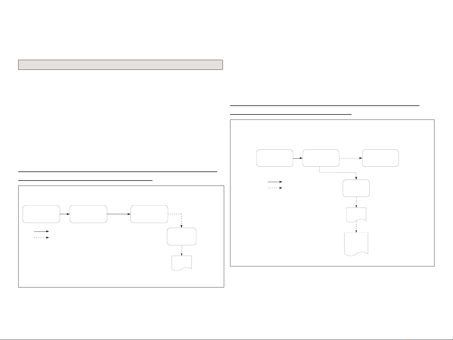
Most Common Congurations.......................................................................9
Lennox Communicating Thermostat, EIM, Non-communicating Furnace,
Non-communicating Air Conditioner or Heat Pump.................................................... 9
Lennox Communicating Thermostat, EIM, Non-communicating Air Handler,
Non-communicating Air Conditioner or Heat Pump.................................................... 9
Lennox S40 Smart Thermostat Only, EIM and Ventilation Only................................. 9
Duel-Fuel Congurations..............................................................................10
Lennox Communicating Thermostat, EIM, Lennox Communicating Furnace and
Non-communicating Heat Pump .............................................................................. 10
Lennox Communicating Thermostat, EIM, Non-Communicating Furnace and
Communicating Heat Pump ..................................................................................... 10
Lennox S40 Smart Thermostat Only, EIM (2), Lennox Communicating
Furnace, 24VAC Heat Pump and Ventilation (ERV/HRV) .........................................11
Thermostat Terminal Information ................................................................11
Field Wiring Diagrams...................................................................................12
Communicating Wiring Diagrams............................................................................. 13
Minimizing Electrical Noise....................................................................................... 14
Alert Codes and Troubleshooting................................................................22
Alert Code Types ...................................................................................................... 22
Alert Codes............................................................................................................... 23
Applications (Ventilation and Zoning) ........................................................31
ERV/HRV Applications ............................................................................................. 31
Fresh Air Damper Application................................................................................... 31
Ventilation Zoning Application .................................................................................. 31
Ventilation Control Modes ........................................................................................ 32
Thermostat Ventilation Parameters .......................................................................... 33
TABLE OF CONTENTS WARNING
Improper installation, adjustment, alteration, service or maintenance can
cause property damage, personal injury or loss of life.
Installation and service must be performed by a licensed professional
HVAC installer (or equivalent) or a service agency.
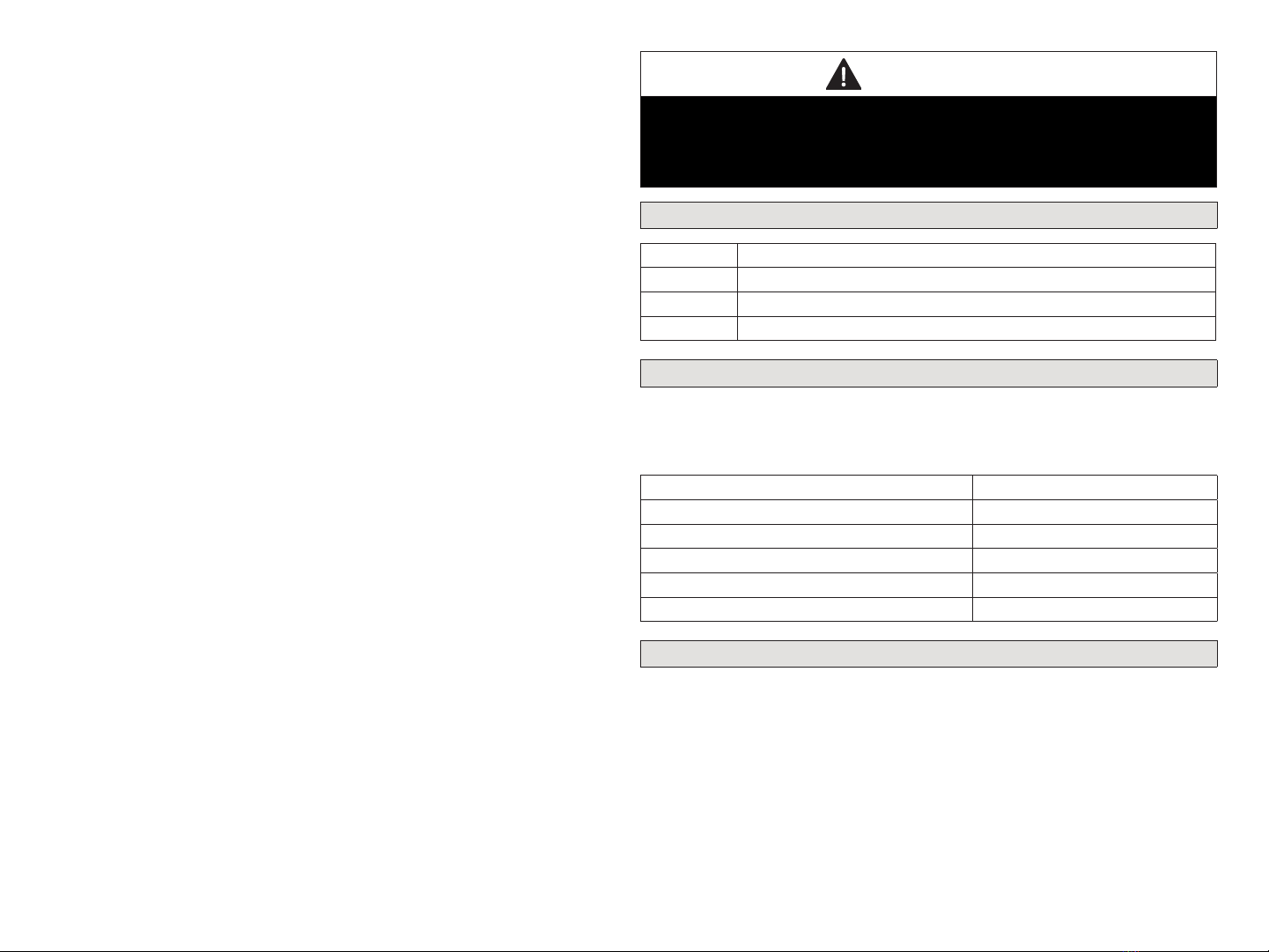
Shipping and Packing List
Quantity Description
1 Equipment Interface Module.
1 Installation and setup guide
1Warranty certicate
Indoor Transformer Requirements
The following lists the required indoor unit transformer rating (VA) for spe-
cic congurations.
Table 1. System VA Loading Chart
Conguration Minimum Transformer Rating (VA)
2-Stage HP, 3-Stage Electric heat and Fresh Air 70
2-Stage HP, 2-Stage Furnace (with tempering) 70
2-Stage HP, 2-Stage Furnace (without tempering) 50
2-Stage AC, 2-Stage Furnace 40
Single stage fresh air damper 6 to 12VA
Overview
The Equipment Interface Module (EIM) is used with an Lennox commu-
nicating thermostat using the R, i+, i-, and C terminals. The EIM is the
interface between non-communicating HVAC equipment and Lennox com-
municating HVAC equipment.
NOTE: EIM will support single-stage outdoor units with single-stage or
variable-stage indoor furnaces.
For ventilation or zoning applications, see “Applications (Ventilation and
Zoning)” on page 31.