Figures
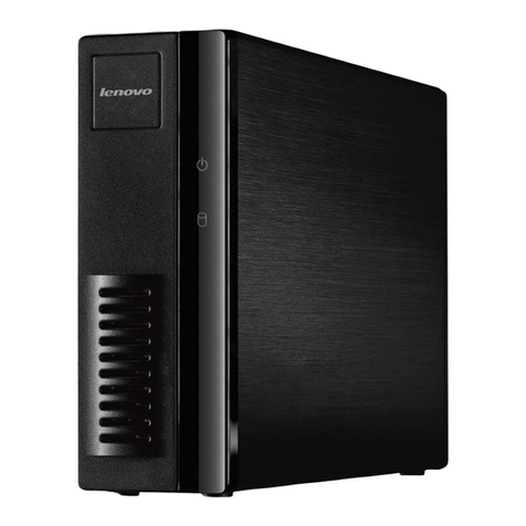
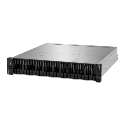
1. Storage block . . . . . . . . . . . . . . 2
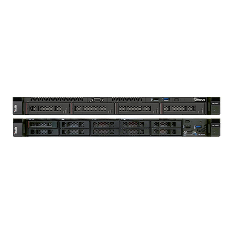
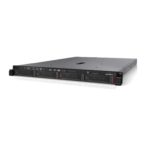
2. Compute block. . . . . . . . . . . . . . 2
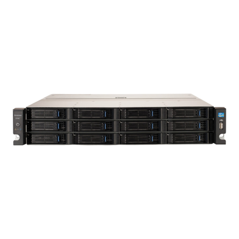
3. CP Interconnect . . . . . . . . . . . . . 3
4. Management switch . . . . . . . . . . . . 3
5. Storage block components . . . . . . . . 11
. Compute block components . . . . . . . 13
7. Cloud Controller Support Mode menu
item . . . . . . . . . . . . . . . . . 23
8. Turn On Support Mode dialog box . . . . . 24
9. Port number and password for Support
Mode connection . . . . . . . . . . . . 24
10. Virtual Office sign-in page . . . . . . . . 24
11. Command to connect to customer’s
interconnect . . . . . . . . . . . . . . 2
12. Cloud Controller Support Mode menu
item . . . . . . . . . . . . . . . . . 28
13. Turn Off Support Mode dialog box . . . . . 28
14. Enclosure indicators. . . . . . . . . . . 30
15. Drive indicators. . . . . . . . . . . . . 31
1 . Storage controller indicators . . . . . . . 32
17. Storage controller port indicators. . . . . . 33
18. Hot-swap drive removal . . . . . . . . . 52
19. Hot-swap drive removal . . . . . . . . . 53
20. Opening the drive tray handle . . . . . . . 5
21. Sliding the drive into the drive bay . . . . . 57
22. Hot-swap power supply removal (1/2) . . . . 4
23. Hot-swap power supply removal (2/2) . . . . 5
24. Hot-swap power supply installation (1/
2) . . . . . . . . . . . . . . . . . . 8
25. Hot-swap power supply installation (2/
2) . . . . . . . . . . . . . . . . . . 9
2 . Hot-swap storage controller removal . . . . 70
27. Hot-swap storage controller installation . . . 71
28. SSH sign-in to proxy server . . . . . . . . 75
29. Entering the proxy server port . . . . . . . 7
30. Entering the proxy server password. . . . . 7
31. Side cover removal . . . . . . . . . . . 78
32. Screws removal . . . . . . . . . . . . 79
33. Enclosure removal from rack . . . . . . . 79
34. Removal of side cover . . . . . . . . . . 81
35. Installing the enclosure into the rack . . . . 82
3 . Installing screws on front of enclosure . . . . 82
37. Reinstalling the side cover . . . . . . . . 83
38. Enable Maintenance Mode for a Node . . . . 88
39. Maintenance Mode dialog box . . . . . . . 89
40. Disable Maintenance Mode for a Node . . . 90
41. Drive removal . . . . . . . . . . . . . 92
42. Drive installation . . . . . . . . . . . . 93
43. Hot-swap power supply removal . . . . . . 9
44. Hot-swap power supply installation . . . . . 99
45. Fan fault LEDs . . . . . . . . . . . . . 101
4 . 0x 0x5 mm fan removal . . . . . . . . 102
47. 80x80x80mm fan removal . . . . . . . . 103
48. 0x 0x5 mm fan installation . . . . . . . 105
49. 80x80x80mm fan installation . . . . . . . 10
50. EIOM ports and corresponding node
number . . . . . . . . . . . . . . . . 107
51. EIOM removal . . . . . . . . . . . . . 108
52. EIOM installation . . . . . . . . . . . . 109
53. DIMM removal . . . . . . . . . . . . . 111
54. Location of the DIMM connectors on the
system board . . . . . . . . . . . . . 113
55. Location of the DIMM connectors on the
system board . . . . . . . . . . . . . 115
5 . DIMM installation . . . . . . . . . . . . 11
57. Recabling management switch from primary
to secondary interconnect . . . . . . . . 123
58. Removing the interconnect from the
rack . . . . . . . . . . . . . . . . . 127
59. Hardware management network connectivity
in a single interconnect configuration . . . . 134
0. Single—interconnect configuration —
compute node and network interconnect
connections . . . . . . . . . . . . . . 13
1. Single—interconnect configuration —
storage block and network interconnect
connections . . . . . . . . . . . . . . 137
2. Hardware management network connectivity
in a dual—interconnect configuration . . . . 138
3. Dual—interconnect configuration —
compute node and network interconnect
connections . . . . . . . . . . . . . . 140
4. Dual—interconnect configuration — storage
block and network interconnect
connections . . . . . . . . . . . . . . 141
5. Dual-interconnect configuration — inter-
interconnect link network connectivity . . . . 141
. Power-cord retention clip removal . . . . . 144
7. Releasing switch unit from the rack . . . . . 145
8. Removing mounting brackets from
switch . . . . . . . . . . . . . . . . 145
9. Attaching mounting brackets to switch . . . 147
70. Securing switch to rack posts . . . . . . . 147
71. Installing power cord retention clip . . . . . 148
© Copyright Lenovo 2018, 2020 iii


