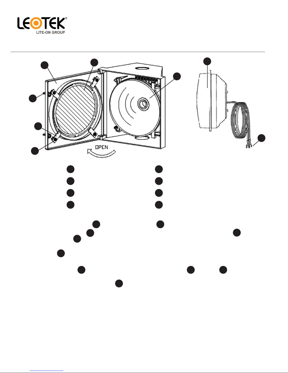
Step 1 - Loosen the two wing-nuts located on the front panel and then open the front panel.
Step 2 - Loosen the four screws on the back side of the front panel and turn the four metal plates to remove
the exisng lens.
Step 3 - Unscrew the exisng incandescent light bulb from the socket (cauon: light bulb may be hot) and remove the
reector.
Step 4 - Remove the protecve lm from the lens of the module.
Step 5 - Mount the module to the front panel. Use the exisng metal plates and screws to mount the
module. For balls, make sure the “TOP” arrow is poinng upward.
Step 6 - Securely connect the spade terminal to the trac signal power terminals, which are connected to the
controller. LED modules have colored wire: red, yellow, and brown wires for phase conductor, and white wire
for neutral line.
Step 7 - Close the panel and ghten the two wing nuts.
Step 8 - If the external exible cable or cord of this module is damaged, it shall be replaced by a special cord or cord
exclusively available from the manufacturer or service agent.
Terminal block not included.
© 2015 Leotek Electronics USA LLC
www.leotek.com
IL Series Installaon Guide_v8_110315
LED Trac Signal Modules
Incandescent Look
IL Series (Type 1)
Informaon provided subject to change without noce.
Leotek Electronics USA LLC | 1955 Lundy Avenue | San Jose, CA 9513
408.380.1788 | www.leotek.com
G
BE
A
D
C
F
H
Wing Nuts
Front Panel
Screws
Metal Plates
Exisng Lens
Socket and Reector
Module
Spade Terminal
A
B
C
D
E
F
G
H
A B
CD
E
F
G D C
H


