LETRIKA 260 User manual

USER MANUAL
SOLAR
MICRO INVERTER 260

2USER MANUAL
Copyright
Trademarks
Who should read this manual
Disclaimer of liability
All rights with respect to this document, including applications for patent and registration of
other industrial property rights, are reserved. Unauthorized use, in particular reproduction or
making available to third parties, is prohibited.
Letrika Sol d.o.o. is registered trademarks of the Mahle Letrika d.o.o.. All other brand or
product names mentioned in this document may be trademarks or registered trademarks of
their respective holders.
This manual is intended to be used during installation, commissioning and maintenance as a
reference for installers, system integrators and other qualified personnel with knowledge of local
standards and regulations. They should always follow local electrical safety and fire protection
guidelines. Only technically qualified personnel should install or replace Letrika Micro inverters.
This manual only describes the product and is not a warranty of performance or characteristic.
Contents of the manual has been reviewed against the hardware and software described. Any
liability can be accepted for any errors or omissions contained in the information given.
The installation, handling and use of Letrika micro inverters are beyond company control.
Letrika Sol d.o.o. does not assume any responsibility for loss, damage, injury or expense
resulting from the improper installation, handling, use or maintenance.
We reserve the right to change this document at any time without notice.

3
USER MANUAL
Introduction 4
Main features 4
PV Power Plant with Letrika Solar Micro inverters 260 5
Hardware Structure of Solar Micro Inverter 260 6
Safety 8
Symbols legend used in this manual and/or equipment 8
Safety and general warnings 8
General installation safety guidelines 9
Installation procedure 10
Compatible PV modules 10
Landscape versus portrait panels placement 11
Mounting hardware compatibility 12
Al profile selection 12
Inverter fixing screws positions 12
Inverter cooling consideration 13
Connecting cables to micro inverter 14
Connecting micro inverter system to utility grid 14
Simple single phase connection with I.P.S. device 15
Single phase connection without I.P.S. interface to grid 15
Three phase connection 16
Trunk cable extension and cable end covering 17
Commissioning 18
Preliminary checks 18
Sequence of operations 18
Troubleshooting 19
List of errors in alarm list 19
Storage 22
Disposal 22
Maintenance 22
Registration and warranty 23
Contact 23
Appendix 24
Technical specification 24
Certificate 25
Identification and oredring code 25
Dimensions 26
Compatible dc connector systems 26
Compatible AC connector system 27
Trunk cable data 27
Accessories 28
Waterproof cap 28
Cable end cap 29
Cable joiner 29
1
1.1
1.2
1.3
2
2.1
2.2
2.3
3
3.1
3.1.1
3.1.2
3.1.2.1
3.1.2.2
3.1.2.3
3.2
3.3
3.3.1
3.3.2
3.3.3
3.3.4
4
4.1
4.2
5
5.1
6
7
8
9
10
Table of contents

4
USER MANUAL
1 Introduction
1.1 Main features
• Nominal Apparent Power 290 VA at power factor f 0,9
• Nominal Real Power 260W
• Nominal Reactive Power 260 VAr at power factor 0.9
• Max. Reactive Power 0-260 VAr (cap., ind.)
• Max efficiency 96,1%
• Large voltage and power input range - corresponds to the majority of 60 and 72-cells PV modules
• Reactive power capability – wide range
• Dynamic power factor
• Integrated relay for safe grid disconnection
• Galvanic isolation of DC side from AC side with HF transformer
• Low ripple current
• 0.0 W standby consumption
• WMBUS standard wireless communication
• DC circuit is isolated and insulated from ground
• Quick installation
• Full power at ambient temperature 65°C
• Die cast aluminum enclosure with completely potted electronics
• IP 67 – dust tight, no ingress of dust; immersion in water up to 1 m for 30 minutes
• Integrated foil capacitors, allowing very long life-time (25 years)
• Design flexibility
• Letrika 50 years’ experience in automotive and heavy duty electronics and electro mechanics
Protection Function
• Over and under voltage protection
• Over and under frequency protection
• Anti-Island protection
• Surge protection device (SPD) integrated
• Mains Monitoring Switching Device (MSD) integrated according to VDE 4105
INTRODUCTION

5
USER MANUAL
1.2 PV Power Plant with Letrika Solar Micro inverters 260
PV power plant with Letrika Solar Micro inverters 260
consists of several components. PV module directly
convert sunlight into DC electricity, micro inverters
change electrical current from DC to AC. Electricity is then
transferred via, trunk cables, junction boxes and main
distribution switch to the grid .
Each PV module is directly connected to Letrika Solar Micro
inverter 260. PV module and micro inverter is individual
power unit operating at maximum available power. The
operation of such power unit is independent and does not
affect the operation and performance of other power units.
PV modules of different characteristic can be installed in
different position and orientation without interfering with
each other.
The operation of micro inverters can be controlled via Linux
based Gateway. Gateway communicates over wireless
WMBUS with Letrika Solar micro inverter 260 and over a
Wi-Fi or Ethernet with computer, smart phone or tablet.
We can monitor and analyze individual micro-inverters or
the whole power plant using browser on computer, smart
phone or tablet.
INTRODUCTION

6
USER MANUAL
Solar Micro inverter converts direct current (DC) generated from a single PV module to alternating current (AC).
Each micro inverter use Maximum Power Point Tracking (MPPT) to maximize production of single PV module.
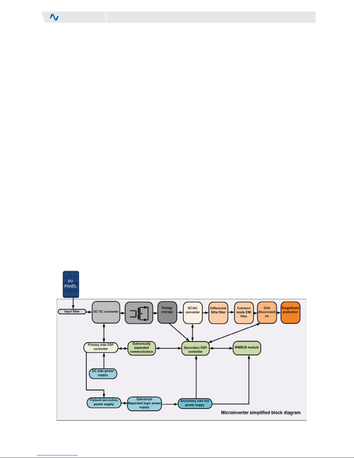
Micro inverter has several functional units:
Input filter on DC side decouples PV panel from high
frequency transients during DCDC converter switching.
DC side power supply of the primary (DCDC) logic is active
until minimum panel voltage is reached.
Primary DSP controller (16bit , 70MIPS, high performance
DSP) calibrates analog system, then starts to sample
PV panel open circuit voltage. After PV voltage reaches
sufficient voltage for reliable start of main flyback power
supply, secondary(AC) side logic is turned on.
At this point, power supply to both power sections is
activated, secondary DSP (32bit,60Mips controller) is
started.
After successful connection with primary DSP controller,
secondary controller will execute auto calibration and
after 10 seconds activate WMBUS RF module. This delay
is necessary for WMBUS module to stabilize operating
parameters and also to avoid unnecessary power ON/OFF
INTRODUCTION
1.3 Hardware Structure of Solar Micro Inverter 260
cycling in case of low irradiation. WMBUS module converts
inverter serial data into 868Mhz data stream according to
WMBUS standard. Data from micro inverter can be received
by Letrika data gateway or by any device compatible with
WMBUS standard.
The power DCDC converter is started in constant current
mode and high voltage. Energy storage capacitor is charged
up to minimum voltage needed for reliable start. Voltage
level in energy storage capacitor changes with grid voltage,
optimizing switching losses on power section. Foiled
capacitors are use because they have lower aging compared
with electrolytic capacitors.
Concurrently DSP2 algorithms are synchronized with grid
and operating limits are checked. Once DC voltage reaches
minimum level, AC inverter power stage is enabled, grid
disconnection relay (if present) is turned on and grid current
is gradually (according to standards limits) increased.
DCDC converter switches to MPPT tracker mode and begins
to track PV panel maximum power point. A high speed

7
USER MANUAL
INTRODUCTION
processor with special algorithm is used to achieve high
efficiency and best possible harvest from sun.
Differential mode filters are used for filtering 50 Hz current
from inverter carrier frequency,, .
Common mode EMC filters are used for EMC interferences
filtering. THD for
Surge and Burst protections are used for protecting inverter
from lightening phenomena’s and grid over voltages. It
is strongly recommended to install external overvoltage
protection class II on AC side, it is also condition for the
validity of Limited Warranty.
Solar Micro inverter is in standby until there is insufficient
irradiance and a specific minimum voltage is present in
the inverter. The consumption in standby is 0W. The micro
inverter starts to fully operate when the sun begins to
supply energy and the voltage in PV module reach 22Vdc.
When the voltage drops below the minimum voltage value
(15Vdc) feed-in mode ends and the inverter switches off.

8
USER MANUAL
SAFETY
2 Safety
CAUTION
Generic danger - Important safety
information.
WARNING
Dangerous voltage. All precautions and pro-
tections against high voltage electric shock
should be taken.
HOT
SURFACE
Danger of burns, do not touch product.
WARNING
Letrika inverters must be installed only by
technically qualified personal.
WARNING
All electrical installations must be performed
in accordance with local and national electrical
standards and codes.
WARNING
Do not connect wet connectors. Connectors must
be dry before any attempt to connect them.
WARNING
Do not cut, bend or modify original connectors
and/or cables supplied with inverters.
WARNING
Lightning protection must be placed on each
inverters branch. Avoid wiring loops or rings.
Keep cable paths short as possible.
WARNING
Inverter and all metal components must be
grounded according to local standards.
2.1 Symbols legend used in this manual and/or equipment
2.2 Safety and general warnings
WARNING
Inverter PV side is galvanically separated from
dangerous voltages; however do not attempt
to disconnect PC cables from inverter during
operation.
WARNING
Always mount grid disconnection switch be-
tween micro inverter installation and grid.
WARNING
There are no user serviceable parts inside
Letrika micro inverter. It is strictly forbidden
any intervention on micro inverter internal
structure.
CAUTION
In case of fault on PV installation with Letrika
micro inverters, do not attempt disconnect PV
or grid cables from inverters or junction boxes
until qualified personal checks the installation.
HOT
SURFACE
Metal surface of Letrika micro inverters can reach
more than 70 degrees in operation. To reduce
risk of burns do not touch the inverter while in
operation. After switching o micro inverter wait
at least 10 minutes before touching it.
Manual shall be consulted that must be
available for future use and not damaged.
Connection to ground protection.
Note. Please read paragraph marked with
this icon carefully.

9
USER MANUAL
SAFETY
CAUTION
Grounding of all metal parts of the
construction is the responsibility of
installer.
WARNING
Micro inverters generates power from more
than one source
WARNING
When micro inverter is connected to PV
module and exposed to light, dangerous
voltages may appear on output in case of
malfunction.
WARNING
Inverters with damaged enclosure or wiring
must not be repaired and must be returned
to producer
WARNING
It is forbidden to connect DC input of micro
inverter to the battery or any other DC
power supply. Solar micro inverter can be
connected only to PV module.
2.3 General installation safety guidelines
WARNING
Use only originally supplied cables. Use
original end cap from ALTW cable producer
to ensure IP67 protection on whole cable
trunk.
CAUTION
Connect circuit breaker with overcurrent
protection according to PV plant power and
local standards.
CAUTION
Always fix cables to the frame. Do not allow
PV and grid cables to float free.
CAUTION
If equipment is not used as specified in
this manual and other Letrika documents,
protection provided by the equipment may
be impaired.
The installation must be wired according to local regulations
and standards where inverters are mounted.
Follow local guidelines for grid monitoring devices and other
safety devices to be located between inverters and grid.
CAUTION
If required by local standards, AC wiring must
be additionally protected with RCDs and Earth
Fault Monitors where required.
CAUTION
Before starting inverters for first time, inspect
the wiring, measure isolation resistance be-
tween PV+,PV- and protective ground.
CAUTION
Micro inverters should be mounted on
aluminum frame holding the PV modules.
Preferably on upper side to avoid prolonged
submersion of inverters into water or snow. Do
not left inverters unfixed on the roof.

10
USER MANUAL
Letrika micro inverters are compatible with monocrystalline
and polycrystalline panels with 60 and 72 cells per panel.
Thin film panels are normally not suitable because of
higher panel dc voltage incompatible with micro inverter
input range. However some thin film panels with output
voltage of approx. 50V can still be used with Letrika micro
inverters. Thin film modules have a risk of TCO corrosion.
Consult the producer of thin film panels how to ground
the positive or negative terminal of the PV module. Letrika
Solar micro inverter 260 allows using the positive or
negative grounding.
PV modules from 220Wp up to 310Wp can be connected
to the inverter. Using lower power PV modules, the micro
During installation it is a good idea to follow a check list of
operations. We will describe general approach that allows
installation of the inverters that is easy to manage and
maintain.
3 Installation procedure
3.1 Compatible PV modules
INSTALLATION PROCEDURE
inverter power is not entirely used, efficiency is lower and
this affect the production of electricity.
When higher power PV modules are used, consider that the
micro inverter can deliver approx. 300W of AC power for
approx. 20 minutes at 30°C.
During selection of PV modules power consider also
average and peak operating ambient temperature. From
the point of view of micro inverter performances, there
is no derating in performances until 65 degrees ambient
temperature is reached.
Open circuit voltages (Uoc) and short circuit currents (Isc)
of PV modules shouldn’t exceed the declared values in
technical specification.

11
USER MANUAL
Portrait or landscape layout could be used when installing
more PV panels.
Layout of PV panels will affect the choice of trunk cable.
If the layout is portrait the distance between the
connections on trunk cable are every 1,05 m.
If the layout is landscape the distance between the AC
connections on trunk cable are every 1,70 m or 2,00 m.
3.1.1 Landscape versus portrait panels placement
INSTALLATION PROCEDURE
Landscape panels orientation
Portrait panels orientation

12
USER MANUAL
INSTALLATION PROCEDURE
Install the mounting screws (M8 x 16) on the body of
the supporting structure at intervals of 130 mm and
installation of the casing by tightening the bolts to torque
Nm 9. Do not over torque.
3.1.2.2 Inverter fixing screws positions
Letrika Solar micro inverter is designed to be compatible
with most standard Al frames. During frame selection few
important thing must be observed.
Al profile must have a T shaped groove for M8 or M6 nut.
M8 screw inserted into T shaped groove. If screw is
inserted it is easier to place and fix the micro inverter.
Screws must be inserted before the frame is assembled,
since they can`t be moved across frame junctions.
If M8 or M6 nuts are inserted into profile care should be
taken during screw length selection, since long screws can
damage the AL profile or they cannot fix micro inverter
adequately.
Use M8 or M6 screws and nuts. Do not use smaller or larger
screws for fixing the micro inverter
Al profile width must match micro inverter fixing tab
length. There are several possibilities how to mount
the inverter on the profile each with advantages and
disadvantages.
3.1.2 Mounting hardware compatibility
3.1.2.1 Al profile selection

13
USER MANUAL
For proper inverter operation and full performance
delivery some mounting guidelines must be observed.
Although micro inverter does not need any forced
ventilation and is cooled by natural heat exchange
with surrounding air, it still need some air around its
aluminum enclosure to cool efficiently.
We strongly suggest to place micro inverter at least
15mm bellow the panel surface and to leave at least
20mm between inverter and underneath surface to
avoid panel heating and micro inverter overheating.
Micro inverter can be positioned above or below
supporting Al frame, as indicated on drawings
bellow. Placing micro inverter on bottom side of Al
support, decrease heat transfer from micro inverter
to solar panel, increasing efficiency on high ambient
temperatures.
Mount micro inverter in locations, which are out of
direct sunlight.
We do not recommend mounting micro inverter directly
between panel and roof surface since air irculation is not
guaranteed. Efficiency of the system will be decreased
and the micro inverter and the panel can be overheated
if mounted like shown on bellow drawing.
If micro inverters are mounted as showed above,
warranty period is voided.
3.1.2.3 Inverter cooling consideration
Recommended mounting for optimal heat dissipation (micro inverter on
top of supporting frame
Forbidden micro inverter mounting
INSTALLATION PROCEDURE
Recommended mounting for optimal heat dissipation (micro inverter on
bottom side of supporting frame)

14
USER MANUAL
It is a good practice to mount inverter in the middle
of the panel width, regardless if the panel is placed in
portrait or landscape position.
Horizontal placement of the inverter
Connecting cables to micro inverter
Connecting cables to micro inverter is simple. Just connect
DC cables connectors into matched panel DC connectors
coming from panel junction box. Push connectors together
until they latch with audible CLICK.
Some DC connectors are marked with + and – engraved on
plastic. Polarity is valid for panel side. On micro inverter,
we placed two additional colored signs on DC wires. BLUE
for DC- and RED for DC+ wire. Please take care about right
polarity while connecting inverters. Before connecting the
inverter measure voltage polarity on PV module.
Insert AC connector from inverter into T junction connector
on the cable. Again, push connectors until audible CLICK is
heard and connector is latched.
Micro inverter must be connected to the utility grid in
accordance with local standards and permissions.
Letrika Solar micro inverter 260 has built in interface
protection system (IPS) according to VDE 4105. All frequency,
voltage and anti-islanding protections are embedded inside
micro inverter. Also power factor, voltage control functions are
built-in. Inside micro inverter is a relay with double contacts
to physically disconnect micro inverter from the grid. External
IPS must be connected between micro inverters and grid if
required by local standards and permission.
3.2 Connecting cables to micro inverter
3.3 Connecting micro inverter system to utility grid
We strongly suggest to mount surge protection devices into
roof junction box or better, to use surge protector systems
that are mounted in same housing as micro inverter and can
be connected to standard ALTW PT 3 wire system allowing
placement of surge protections also in between micro
inverters improving surge immunity.
Please contact Letrika Sol for details on surge protection
devices.
INSTALLATION PROCEDURE

15
USER MANUAL
Single phase system with I.P.S
Single phase connection without I.P.S inteface
Inverters are simply connected to ALTW PT-3 trunk cable.
See table 1 for maximum allowed number n of micro
inverters per trunk.
Not used T junctions on trunk cable must be covered with
watertight cap.
Since Letrika micro inverters have built in I.P.S. according
to VDE 4105 standard with incorporated disconnection
relay, they can be used, if a local standard permits,
3.3.1 Simple single phase connection with I.P.S. device
3.3.2 Single phase connection without I.P.S. interface to grid
I.P.S. device may vary from country to country, please
check with local distributor company.
without additional I.P.S device interfacing to grid, only grid
disconnection switch must be used.
INSTALLATION PROCEDURE

16
USER MANUAL
Micro inverters can be connected also on three phase grid
system. Although they can operate even in event of one or
two phase failure, it is generally not recommended, and in
3.3.3 Three phase connection
some countries also forbidden to operate with one or more
phases interrupted or in short circuit. It is recommended to
use protection against unbalanced load.
INSTALLATION PROCEDURE

17
USER MANUAL
Guidelines for trunk cable extension and cable end covering
are showed below. It’s not allowed to extend the trunk cable
above maximum number of T junctions specified in Table 1.
Trunk extension is normally necessary when panels and micro
inverters are mounted on different places on the roof, making
difficult to connect them only by using trunk cable.
Always use original cable joiner CX-04BCM32-7002 to ensure
trunk cable join point water tightness.
3.3.4 Trunk cable extension and cable end covering
Insert CAP-WTCASMA2 on exposed cable end since original
water tight cap ensure IP67 protection of exposed trunk
cable end.
If trunk extension is done by using customer supplied cable,
please note that the cable must be UV reinforced cable with
cold bending 90 degrees at -40°, 90° maximum temperature.
Figure 12 Trunk cable extension and cable ending
INSTALLATION PROCEDURE

18
USER MANUAL
COMMISSIONING
• Check the data on micro inverter and verify compliance
of these data with grid data
• Peel the label with Serial number and attach it to the
matrix in the same order as they are installed.
• When conducting the checks, ensure that the main AC
disconnector switch (downstream from the system) and
any other possible isolation switches are switched off
position
• Ensure that all conductors and protective grounding
points are connected
• Switch on the main AC disconnector switch
(downstream from the system) and any other possible
isolation switches
• Proceed with configuration of Gateway. Details are
described in Gateway User Manual.
Commissioning should be done by technically qualified personal.
Connecting cable output AC and DC voltage input cables
should be carried out in accordance with the manufacturer's
instructions (AMPHENOL).
4 Commissioning
4.1 Preliminary checks
4.2 Sequence of operations
• Check the position of all connection cables and the
tightness of all nuts and terminals
• Check the micro inverter is firmly mounted
• Ensure that all electrical safeguards have been correctly
installed
• Ensure that the complete system has been checked,
tested and approved in accordance with the local
standards and codes

19
USER MANUAL
TROUBLESHOOTING
The operating state of the micro inverters can be
monitored on the Gateway LCD. LCD shows the status of
the plant on default view. In normal operation the status
is »working«, it means that everything is OK.
If an internal or external fault occurred, the LCD displays
status: »alarm« . Gateway stores errors in alarm list, which
5 Troubleshooting
5.1 List of errors in alarm list
can be at any time retrieved from it with web application.
The inverter will not feed the grid while the alarm on LCD is
present.
Only technically qualified personal may perform work on
electrical installation.
Example of Alarm history from web application
1ERR_OVER_
CURRENT_SW
Over current on AC side is detected by software.
Possible cause is short circuit on grid lines or sudden voltage drop on grid lines.
Proposed action:
• Check connecting lines
• Check surge protections on lines
• Check external power capacitors banks for power factor corrections
• Scan grid voltage for deeps
2ERR_OVER_
CURRENT_HW
Over current is detected by hardware. Possible cause is very high short circuit current, very
deep voltage transients or high voltage surge spikes.
Proposed action:
• Check connecting lines
• Check surge protections on lines
• Check external power capacitors banks for power factor corrections
• Scan grid voltage for deeps
3ERR_OVER_
VOLTAGE
This signal is active if DC high voltage too high.
Possible cause for DC high voltage to rise above safety limits is very unstable grid with
changing shadows on PV module.
Proposed action:
High voltage spikes from grid are transferred to DC high voltage capacitors
Check grid voltage and transients

20
USER MANUAL
4ERR_UNDER_
VOLTAGE
DC high voltage is too low. During operation on high output power, deep shadowing occurred.
It is possible that DC voltage drops too low and it is not possible to push the current into the
grid.
Proposed action:
• Check DC connectors
• If under voltage is repeated on same panels, check all connections
5ERR_ADC Internal circuit problem
Internal circuit calibration failed
Proposed action:
• Replace inverter
6ERR_PANEL_
VOLTAGE_LOW
Panel voltage is too low to operate. Inverter detected too low voltage on PV panel to ensure
correct energy transfer to secondary side.
Proposed action:
• Wait panel voltage to rise up, if this error insist under heavy sun, then check panel voltage
or replace inverter
7ERR_OVER_
TEMPERATURE_
CONTROLLER
DC or AC side power section over temperature.
Temperature on DC or AC power section reached maximum allowed temperature, approx. 90
degrees centigrade.
Proposed action:
• check ambient temperature is lower then 65 degrees
• check inverter exposure to direct sun light
• air is not circulating across inverter enclosure
8ERR_PARAMETERS_
CORRUPTED
Internal Country and other parameters corrupted.
Internal FRAM memory corrupted.
Proposed action:
• Replace inverter
9ERR_ADC_OFFSET_
ERROR
Internal ADC oset to high.
Internal analog to digital converter oset is out of adjustable range.
Proposed action:
• Replace inverter
10 ERR_INTERPROC_COM CRC error in interprocessor communication.
An CRC error occurred between both DSP controllers on inverter.
Proposed action:
• Error should reset automatically after some time, if not, replace inverter
11 ERR_GRID_VOLTAGE Grid voltage to high or too low.
Grid voltage is out of limits, according to country standard.
Proposed action:
• Too much inverters on grid line
• Installation close to grid low voltage transformer
• Grid without power factor correction capability
TROUBLESHOOTING
Table of contents
Popular Inverter manuals by other brands

NEP
NEP BDM-300 Installation and operation manual

Nelinor
Nelinor GRID BATTERY user guide

PowerTech
PowerTech MI5700 user manual

Turbo Energy
Turbo Energy Lithium Slim Series Quick installation guide

Magnum Energy
Magnum Energy MS Series owner's manual

TECO-Westinghouse
TECO-Westinghouse E510-201-H-U Installation and start-up manual