LeuchtKraft RGBL-412DMX User manual

RGBL-412DMX
Bestell-Nr. • Order No. 38.6440
BEDIENUNGSANLEITUNG
INSTRUCTION MANUAL
MODE D’EMPLOI
ISTRUZIONI PER L’USO
MANUAL DE INSTRUCCIONES
INSTRUKCJA OBSŁUGI
VEILIGHEIDSVOORSCHRIFTEN
SIKKERHEDSOPLYSNINGER
SÄKERHETSFÖRESKRIFTER
TURVALLISUUDESTA
LED-DMX-Lichteffekt-Panel
LED DMX Light Effect Panel
LEUCHTKRAFT

2
ENTERMENU/ ESC UP DOWN
➀Menüstruktur • Menu structure
Structure du menu • Struttura del menù
Estructura del menú • Struktura menu
Automatisch ablaufende Programme
Automatic programs
Programmes à déroulement automatique
Programmi a svolgimento automatico
Programas automáticos
Programy automatyczne
DMX-Steuerung
DMX control
Gestion DMX
Comando DMX
Control DMX
Sterowanie DMX
Anzahl der DMX-Kanäle
Number of DMX channels
Nombre de canaux DMX
Numero dei canali DMX
Número de canales DMX
Liczba kanałów DMX
Farbstrahler
Colour spotlight
Projecteur couleur
Proiettore di colori
Proyector de color
Kolorowy reflektor
Slave-Modus • Slave mode
Mode slave • Modo slave
Modo Slave • Tryb slave
Musiksteuerung
Music control
Gestion musique
Comando musica
Control por música
Sterowanie muzyką
Firmware-Version • Firmware version
Version Firmware • Versione Firmware
Versión del Firmware • Wersja firmware'a

SAFETY EYE
ATTACHSAFETY
CABLEHERE
DMXIN DMXOUT MENU/ESC DOWN UP ENTER
230V~/ 50 Hz
SENSITIVITY
MIN MAX
MIC
3
12
2 3 4 45 21 1
4
➁
English
English Page
Contents
Français
Français Page
Table des matières
Italiano
Italiano Pagina
Indice
Español
Español Página
Contenidos
Nederlands
Nederlands Pagina
Inhoud
Polski
Polski Strona
Spis treści
Deutsch
Deutsch Seite
Inhalt
Inhalt
1 Einsatzmöglichkeiten . . . . . . . . . . . 4
2 Übersicht . . . . . . . . . . . . . . . . . 4
3 Hinweise für den sicherenGebrauch . . . 4
4 Montage . . . . . . . . . . . . . . . . . 5
5 Inbetriebnahme . . . . . . . . . . . . . 5
6 Bedienung . . . . . . . . . . . . . . . . 5
6.1 Bedienung über das Menü . . . . . . . . . . 6
6.2 Farbstrahler . . . . . . . . . . . . . . . . 6
6.3 Automatisch ablaufende Programme. . . . . . 6
6.4 Musiksteuerung . . . . . . . . . . . . . . 6
6.5 Synchrone Steuerung mehrerer RGBL-412DMX . 7
6.6 Betrieb mit einem DMX-Steuergerät . . . . . . 7
6.6.1 DMX-Anschluss . . . . . . . . . . . . . . 7
6.6.2 Anzahl der DMX-Kanäle einstellen . . . . . . 7
6.6.3 DMX-Startadresse einstellen. . . . . . . . . 7
6.6.4 DMX-Kanäle und -Funktionen . . . . . . . . 8
6.7 Anzeige der Firmware-Version . . . . . . . . 9
7 Reinigung des Gerätes . . . . . . . . . . 9
8 Technische Daten . . . . . . . . . . . . . 9
Deutsch
LED-DMX-Lichteffekt-Panel
Diese Anleitung richtet sich an den Installateur des
Geräts und an den Bediener mit Grundkenntnissen
in der DMX-Steuerung. Bitte lesen Sie die Anleitung
vor dem Betrieb gründlich durch und heben Sie sie
für ein späteres Nachlesen auf. Auf der Seite 2 ist
die Menüstruktur abgebildet.
1 Einsatzmöglichkeiten
Das Lichteffekt-Panel RGBL-412DMX dient zur
Effektbeleuchtung (z.B. zum Abstrahlen von far-
bigem Licht oder zum Erzeugen von Lauflicht- und
Stroboskopeffekten) und ist für den Einsatz auf
Bühnen, in Diskotheken etc. geeignet. Als Licht-
quelle sind 16 extrem helle RGBW-LEDs eingesetzt.
Das Lichteffekt-Panel ist für die Steuerung über
ein DMX-Lichtsteuergerät ausgelegt (wahlweise 4,
6, 10, 18, 32 oder 34 DMX-Kanäle). Es kann aber
auch ohne Steuergerät betrieben werden, entwe-
der als Einzelgerät oder im Master-Slave-Modus.
2 Übersicht
1 Feststellschrauben für die Montagewinkel
2
Montagewinkel (2 ×) zum Festschauben des
Geräts an einer Wand oder Decke
3 Sicherungsöse zum Befestigen eines Fangseils
4 Feststellschrauben für den Montagebügel
5 Montagebügel
6
XLR-Einbaustecker DMX IN: DMX-Signalein-
gang zum Anschluss eines Lichtsteuergerätes
oder an den DMX-Signalausgang eines anderen
DMX-gesteuerten Gerätes
7
XLR-Buchse DMX OUT: DMX-Signalausgang
zum Anschluss an den DMX-Eingang eines
weiteren DMX-gesteuerten Gerätes
8
Tasten zur Auswahl des Betriebsmodus und zum
Ändern von Einstellungen über das Menü
9 Display
10 Mikrofon zur Musiksteuerung
11
Regler SENSITIVITY für die Ansprechempfindlich-
keit bei Musiksteuerung über das Mikrofon (10)
12 Netzbuchse zum Anschluss an eine Steckdose
(230V/50 Hz) über das beiliegende Netzkabel
13 Halterung für die Netzsicherung
Eine geschmolzene Sicherung nur durch eine
gleichen Typs ersetzen.
3 Hinweise für den
sicherenGebrauch
Das Gerät entspricht allen relevanten Richtlinien
der EU und trägt deshalb das -Zeichen.
WARNUNG
Das Gerät wird mit lebensgefähr-
licher Netzspannung versorgt.
Nehmen Sie deshalb niemals selbst
Eingriffe daran vor. Es besteht die
Gefahr eines elektrischen Schlages.
•
Verwenden Sie das Gerät nur im Innenbereich
und schützen Sie es vor Tropf- und Spritzwasser,
hoher Luftfeuchtigkeit und Hitze (zulässiger Ein-
satztemperaturbereich 0–40 °C).

5
Deutsch
DMX IN DMX OUT ENTER
230V~/50Hz
SENSITIVITY
MIN MAX
MIC
3
1
2
UPDOWNMENU/ESC
6 7 8 9 10 11 12 13
➂
•
Stellen Sie keine mit Flüssigkeit gefüllten Gefäße,
z.B. Trinkgläser, auf das Gerät.
•
Nehmen Sie das Gerät nicht in Betrieb oder zie-
hen Sie sofort den Netzstecker aus der Steck-
dose,
1. wenn sichtbare Schäden am Gerät oder am
Netzkabel vorhanden sind,
2. wenn nach einem Sturz oder Ähnlichem der
Verdacht auf einen Defekt besteht,
3. wenn Funktionsstörungen auftreten.
Geben Sie das Gerät in jedem Fall zur Reparatur
in eine Fachwerkstatt.
•
Ziehen Sie den Netzstecker nie am Kabel aus
der Steckdose, fassen Sie immer am Stecker an.
•
Wird das Gerät zweckentfremdet, nicht sicher
montiert, nicht richtig angeschlossen, falsch
bedient oder nicht fachgerecht repariert, kann
keine Haftung für daraus resultierende Sach-
oder Personenschäden und keine Garantie für
das Gerät übernommen werden.
Soll das Gerät endgültig aus dem Betrieb
genommen werden, übergeben Sie es zur
umweltgerechten Entsorgung einem ört-
lichen Recyclingbetrieb.
4 Montage
Platzieren Sie das Gerät immer so, dass im Betrieb
eine ausreichende Luftzirkulation gewährleistet ist.
Die Lüftungsöffnungen am Gehäuse dürfen auf
keinen Fall abgedeckt werden.
WARNUNG
Das Lichteffekt-Panel muss fachge-
recht und sicher montiert werden.
Wird es an einer Stelle installiert,
unter der sich Personen aufhalten
können, muss es zusätzlich gesichert werden
[z.B. durch ein Fangseil; das Fangseil durch die
Sicherungsöse (3) führen und so befestigen, dass
der Fallweg des Gerätes nicht mehr als 20cm
betragen kann].
Wird eine Fläche angestrahlt, sollte der Abstand
zur Fläche mindestens 50cm betragen.
1. Das Lichteffekt-Panel kann über seinen Mon-
tagebügel (5) an geeigneter Stelle festge-
schraubt werden, z.B. mit einer stabilen Mon-
tageschraube oder einer Lichtstrahler-Halterung
(C-Haken) an einer Traverse.
2. Alternativ dazu lässt sich das Gerät auch über
die zwei Montagewinkel (2) an einer Wand oder
Decke montieren oder auf dem Boden aufstel-
len. Die Winkel mit jeweils einer Griffschraube
(1) links und rechts am Gerät befestigen.
Zum Ausrichten des Geräts die zwei Feststellschrau-
ben (1 oder 4) lösen. Die gewünschte Neigung
des Geräts einstellen und die Schrauben wieder
festziehen.
5 Inbetriebnahme
WARNUNG Blicken Sie nicht direkt in die Licht-
quelle, das kann zu Augenschäden
führen.
Beachten Sie, dass sehr schnelle
Lichtwechsel bei fotosensiblen
Menschen und Epileptikern epi-
leptische Anfälle auslösen können!
Das beiliegende Netzkabel zuerst in die Netzbuchse
(12) stecken und anschließend in eine Steckdose
(230V/50 Hz). Das Gerät ist damit eingeschaltet.
Das Display (9) zeigt für einige Sekunden die letzte
Einstellung an (Seite 2, Abb. 1) und erlischt
anschließend.
Hinweis: Das Gerät verfügt über einen Überhitzungs-
schutz. Dadurch schaltet es sich bei zu hoher Temperatur
ab und nach dem Abkühlen automatisch wieder ein.
6 Bedienung
Das Auswählen des Betriebsmodus und der ver-
schiedenen Funktionen erfolgt über ein Menü
(Seite 2, Abb. 1) mit den Tasten MENU/ESC,
UP, DOWN und ENTER (8). Zur Bedienung über ein
DMX-Lichtsteuergerät siehe Kapitel 6.6.

6
Deutsch
DMX IN DMX OUT ENTER
230V~/50Hz
SENSITIVITY
MIN MAX
MIC
3
1
2
UPDOWNMENU/ESC
➃
6.1 Bedienung über das Menü
1)
Die Taste MENU/ESC so oft drücken, bis sich die
Anzeige im Display nicht mehr ändert. Damit
ist die oberste Menüebene erreicht (☞ Abb.1
ganz links).
2)
Mit der Taste UP oder DOWN den gewünschten
Menüpunkt anwählen.
3)
Die Taste ENTER drücken. Das Display zeigt jetzt
die aktuelle Einstellung des gewählten Menü-
punkts an.
4)
Mit der Taste UP oder DOWN die Einstellung
ändern.
5)
Wenn Untermenüpunkte vorhanden sind, kön-
nen diese mit der Taste ENTER aufgerufen wer-
den und deren Einstellungen mit der Taste UP
oder DOWN geändert werden.
6)
Zum Speichern einer Einstellung die Taste ENTER
drücken.
7) Für weitere Einstellungen wieder mit dem Be-
dienschritt 1 beginnen.
Wird einige Sekunden lang keine Taste gedrückt,
erlischt das Display. Beim nächsten Tastendruck
leuchtet es wieder.
6.2 Farbstrahler
Soll das Lichteffekt-Panel konstant eine Farbe
abstrahlen, kann zwischen neun voreingestellten
Farben und einer individuell einstellbaren Farbe
gewählt werden:
1)
Die Taste MENU/ESC so oft drücken, bis sich die
Anzeige im Display nicht mehr ändert.
2)
Die Taste UP oder DOWN so oft drücken, bis
das Display anzeigt.
3) Die Taste ENTER drücken. Die zuletzt gewählte
Farbe ist eingeschaltet:
… = voreingestellte Farbe
= individuelle Farbeinstellung
Mit der Taste UP oder DOWN die gewünschte
Farbe auswählen.
4)
Zum Einstellen einer individuellen Farbe den
Menüpunkt wählen und die Taste ENTER
drücken. Das Display zeigt die zuletzt einge-
stellte Farbe an:
= Rot
= Grün
= Blau
= Weiß
5)
Mit der Taste DOWN oder UP die Farbe auswäh-
len und die Taste ENTER drücken. Das Display
zeigt nun den Buchstaben für die Farbe ( , ,
oder ) und den zugehörigen Helligkeitswert
(000 … 255) an.
6)
Die gewünschte Helligkeit mit der Taste UP oder
DOWN einstellen.
7) Mit der Taste MENU/ESC den Menüpunkt wie-
der verlassen. Jetzt kann die nächste Farbe an-
gewählt und eingestellt werden.
6.3 Automatisch ablaufende
Programme
Über den Menüpunkt können drei verschie-
dene Programme ausgewählt werden:
= Farbwechsel 1 (langsam)
= Farbwechsel 2 (schnell)
= verschiedene Lauflichteffekte
Die Ablaufgeschwindigkeit lässt sich in neun Stufen
(… ) ändern.
6.4 Musiksteuerung
Bei der Musiksteuerung leuchten die LEDs durch
über das Mikrofon (MIC) aufgenommene Schall-
ereignisse auf. Drei Programme ( , ,
) können ausgewählt werden.
1)
Das gewünschte Programm über den Menü-
punkt einschalten.
2) Den Regler SENSITIVITY für die Mikrofonemp-
findlichkeit so einstellen, dass die LEDs optimal
durch die Musik gesteuert werden. Je weiter
der Regler aufgedreht wird, desto empfindlicher
reagiert die Musiksteuerung.
Hinweis: Beim Ändern der Lautstärke an der Musikanlage
muss auch die Mikrofonempfindlichkeit mit dem Dreh-
regler entsprechend angepasst werden.

7
Deutsch
6.5 Synchrone Steuerung mehrerer
RGBL-412DMX
(Master-Slave-Modus)
Es lassen sich mehrere RGBL-412DMX zusammen-
schließen. Das Hauptgerät (Master) kann dann alle
Nebengeräte (Slave) synchron steuern.
1)
Die Geräte über die DMX-Anschlüsse mitei-
nander zu einer Kette verbinden. Siehe dazu
Kapitel 6.6.1 „DMX-Anschluss“, jedoch ohne
den Bedienschritt 1 zu beachten.
2)
Das erste Gerät der Kette (dessen Eingang
DMX IN nicht angeschlossen ist) dient als
Hauptgerät und steuert die Nebengeräte. Die
Nebengeräte auf den Slave-Modus einstellen:
a)
Die Taste MENU/ESC so oft drücken, bis sich
die Anzeige im Display nicht mehr ändert.
b)
Die Taste UP oder DOWN so oft drücken, bis
das Display anzeigt.
c) Die Taste ENTER drücken. Das Display schal-
tet auf um.
6.6 Betrieb mit einem DMX-Steuergerät
Zur Bedienung über ein DMX-Lichtsteuergerät
(z.B. DMX-1440 oder DMX-510USB von IMG
STAGELINE) verfügt das Lichteffekt-Panel über 34
DMX-Steuerkanäle. Er lässt sich je nach Bedarf aber
auch über nur 32, 18, 10, 6 oder 4 Kanäle steu-
ern. DMX ist die Abkürzung für Digital Multiplex
und bedeutet digitale Steuerung von mehreren
DMX-Geräten über eine gemeinsame Steuerlei
-
tung. Die Funktionen der Kanäle und die DMX-
Werte sind im Kapitel 6.6.4 angegeben.
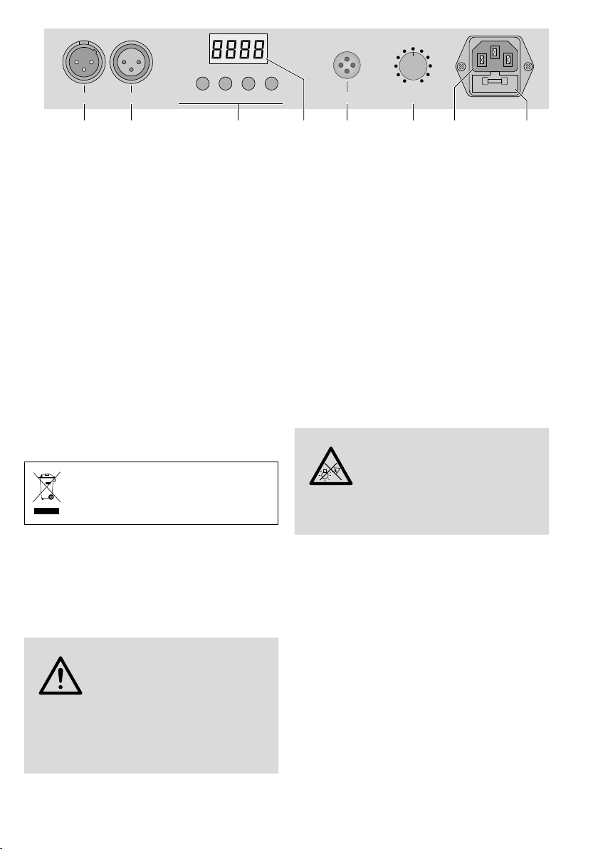
6.6.1 DMX-Anschluss
Zum Anschluss sollten spezielle Kabel für die
DMX-Signalübertragung verwendet werden (z.B.
Kabel der CDMXN-Serie von IMG STAGELINE). Bei
Leitungslängen ab 150m wird grundsätzlich das
Zwischenschalten eines DMX-Aufholverstärkers
empfohlen (z.B. SR-103DMX).
1) Den Eingang DMX IN mit dem DMX-Ausgang
des Lichtsteuergerätes verbinden.
2)
Den Ausgang DMX OUT mit dem DMX-Ein-
gang des nächsten DMX-Gerätes verbinden.
Dessen Ausgang wieder mit dem Eingang des
nachfolgenden DMX-Gerätes verbinden usw.,
bis alle DMX-gesteuerten Geräte in einer Kette
angeschlossen sind.
3)
Um Störungen bei der Signalübertragung
auszuschließen, sollte bei langen Leitungen
bzw. bei einer Vielzahl von hintereinander-
geschalteten Geräten der DMX-Ausgang des
letzten DMX-Gerätes der Kette mit einem
120-Ω-Widerstand (> 0,3 W) abgeschlossen
werden: In die DMX-Ausgangsbuchse einen
entsprechenden Abschlussstecker (z.B. DLT-123
von IMG STAGELINE) stecken.
6.6.2 Anzahl der DMX-Kanäle einstellen
Um das RGBL-412DMX mit einem Lichtsteuergerät
bedienen zu können, müssen die DMX-Startadresse
(☞Kap. 6.6.3) und die Anzahl der DMX-Kanäle
eingestellt werden. Die Anzahl der DMX-Kanäle
hängt von den benötigten Funktionen ab und
eventuell auch von der Anzahl der verfügbaren
Steuerkanäle am Lichtsteuergerät. Informieren Sie
sich bitte im Kapitel 6.6.4 über die Funktionen,
die jeweils möglich sind und wählen Sie danach
die Anzahl aus:
1)
Die Taste MENU/ESC so oft drücken, bis sich die
Anzeige im Display nicht mehr ändert.
2)
Die Taste UP oder DOWN so oft drücken, bis
das Display anzeigt.
3) Die Taste ENTER drücken. Das Display zeigt die
momentane Einstellung an:
… = 4 … 34 Kanäle
4) Die Anzahl mit der Taste UP oder DOWN ein-
stellen und zum Speichern die Taste ENTER
drücken.
6.6.3 DMX-Startadresse einstellen
Um alle am Lichtsteuergerät angeschlossenen
DMX-Geräte separat bedienen zu können, muss
jedes Gerät eine eigene Startadresse erhalten.
Soll der erste DMX-Kanal des RGBL-412DMX vom
Lichtsteuergerät z.B. über die DMX-Adresse 17
gesteuert werden, am RGBL-412DMX die Start-
adresse 17 einstellen. Alle weiteren DMX-Kanäle
des RGBL-412DMX sind dann automatisch den
darauffolgenden Adressen zugeordnet. Beispiele
mit verschiedenen Startadressen:
Anzahl der
DMX-
Kanäle
Start-
adresse
vom RGBL-
412DMX belegte
Adressen
nächstmögliche Start-
adresse für das nachfol-
gende DMX-Gerät
411 – 4 5
17 17 – 20 21
611 – 6 7
17 17 – 22 23
10 1 1 – 10 11
18 25 25 – 42 43
32 73 73 – 104 105
34 13 13 – 46 47
479 479 – 512 –
➄DMX-Adressenbelegung des RGBL-412DMX

8
Deutsch
Die Startadresse über den Menüpunkt ein-
stellen. Danach lässt sich das Lichteffekt-Panel mit
dem Lichtsteuergerät bedienen.
Hinweise:
Für die DMX-Steuerung muss immer die DMX-Startad-
resse über das Menü angewählt sein.
Im Display blinkt ein Punkt, wenn DMX-Signale am
DMX-Eingang (DMX INPUT) anliegen.
6.6.4 DMX-Kanäle und -Funktionen
1 2 3 4 5 6 7 8 9 10 11 12 13 14 15 16
➅Nummerierung der LEDs
Wichtig: Für die DMX-Steuerung muss immer die DMX-Startadresse über das Menü angewählt sein.
Funktion
Kanal 4 Kanäle 6 Kanäle 10 Kanäle 18 Kanäle 34 Kanäle 32 Kanäle
1R: LEDs 1–16 Modus R: LEDs 1+2
2G: LEDs 1–16 Stroboskop-Frequenz/Ablaufgeschwindigkeit G: LEDs 1+2
3B: LEDs 1–16 R: LEDs 1–16 R: LEDs 1–8 R: LEDs 1–4 R: LEDs 1+2 B: LEDs 1+2
4W: LEDs 1–16 G: LEDs 1–16 G: LEDs 1–8 G: LEDs 1– 4 G: LEDs 1+2 W: LEDs 1+2
5B: LEDs 1–16 B: LEDs 1–8 B: LEDs 1–4 B: LEDs 1+2 R: LEDs 3 +4
6W: LEDs 1–16 W: LEDs 1–8 W: LEDs 1–4 W: LEDs 1+2 G: LEDs 3+4
7R: LEDs 9–16 R: LEDs 5–8 R: LEDs 3+4 B: LEDs 3+4
8G: LEDs 9–16 G: LEDs 5–8 G: LEDs 3+ 4 W: LEDs 3+4
9B: LEDs 9–16 B: LEDs 5–8 B: LEDs 3+4 R: LEDs 5+6
10 W: LEDs 9–16 W: LEDs 5–8 W: LEDs 3+4 G: LEDs 5+6
11 R: LEDs 9–12 R: LEDs 5+6 B: LEDs 5+6
12 G: LEDs 9–12 G: LEDs 5+6 W: LEDs 5+ 6
13 B: LEDs 9–12 B: LEDs 5+6 R: LEDs 7+8
14 W: LEDs 9–12 W: LEDs 5+6 G: LEDs 7+8
15 R: LEDs 13–16 R: LEDs 7+8 B: LEDs 7+8
16 G: LEDs 13–16 G: LEDs 7+8 W: LEDs 7+8
17 B: LEDs 13–16 B: LEDs 7+8 R: LEDs 9+10
18 W: LEDs 13–16 W: LEDs 7+ 8 G: LEDs 9+10
19 R: LEDs 9+10 B: LEDs 9+10
20 G: LEDs 9+10 W: LEDs 9+10
21 B: LEDs 9+10 R: LEDs 11+12
22 W: LEDs 9+10 G: LEDs 11+ 12
23 R: LEDs 11+12 B: LEDs 11+12
24 G: LEDs 11+12 W: LEDs 11+12
25 B: LEDs 11+12 R: LEDs 13+14
26 W: LEDs 11+12 G: LEDs 13+ 14
27 R: LEDs 13+14 B: LEDs 13+14
28 G: LEDs 13+14 W: LEDs 13+14
29 B: LEDs 13+14 R: LEDs 15+16
30 W: LEDs 13+14 G: LEDs 15+ 16
31 R: LEDs 15+16 B: LEDs 15+16
32 G: LEDs 15+16 W: LEDs 15+16
33 G: LEDs 15+16
34 W: LEDs 15+16
➆DMX-Kanalbelegung R = Rot, G = Grün, B = Blau, W = weiß

9
Deutsch
Kanal DMX-Wert Funktion
1*
000–007 Farbstrahler: Farbe und Helligkeit über die Kanäle > 2 einstellen
008–015 Steuerprogramm 1
016–023 Steuerprogramm 2
024–031 Steuerprogramm 3
… …
216–223 Steuerprogramm 27
224–231 Steuerprogramm 28
232–239 Musiksteuerung SOUND 1
240–247 Musiksteuerung SOUND 2
248–255 Musiksteuerung SOUND 3
2*
wenn Kanal 1 = 000–007
000–007 Stroboskop aus
008–255 Stroboskop langsam schnell
wenn Kanal 1 = 008–231
000–255 Ablaufgeschwindigkeit langsam schnell
R000–255 Helligkeit Rot
G000–255 Helligkeit Grün
B000–255 Helligkeit Blau
W000–255 Helligkeit Weiß
➇DMX-Werte *nur beim Betrieb über 6, 10, 18 oder 34 Kanäle
6.7 Anzeige der Firmware-Version
Um die Versionsnummer der Firmware (Betriebs-
software des Gerätes) anzuzeigen:
1)
Die Taste MENU/ESC so oft drücken, bis sich die
Anzeige im Display nicht mehr ändert.
2)
Die Taste UP oder DOWN so oft drücken, bis
das Display (version) anzeigt.
3) Die Taste ENTER drücken. Das Display zeigt für
einige Sekunden die Versionsnummer an. Da-
nach erlischt es.
4)
Mit den Bedientasten zurück auf die ge-
wünschte Betriebsart schalten.
7 Reinigung des Gerätes
Die Kunststoffscheibe vor den LEDs sollte in regel-
mäßigen Abständen, je nach Verschmutzung durch
Staub, Rauch oder andere Schmutzpartikel gerei-
nigt werden. Nur dann kann das Licht in maxima-
ler Helligkeit abgestrahlt werden. Zum Säubern
den Netzstecker aus der Steckdose ziehen.
Nur ein weiches, sauberes Tuch und ein mildes
Reinigungsmittel verwenden. Anschließend die
Kunststoffscheibe trocken wischen.
Zum Reinigen der anderen Gehäuseteile nur
ein weiches, sauberes Tuch benutzen. Auf keinen
Fall eine Flüssigkeit verwenden, die könnte in das
Gerät laufen und Beschädigungen verursachen.
8 Technische Daten
Datenprotokoll:. . . . . . . DMX 512
Anzahl
der DMX-Kanäle: . . . . . 4, 6, 10, 18, 32 oder34
Lichtquelle: . . . . . . . . . . 16 RGBW-LEDs
Leistung je LED: . . . . . 8 W
Stromversorgung: . . . . . 230V/50Hz
Leistungsaufnahme: . . . max. 170VA
Abmessungen ohne
Montagewinkel
(B × H × T) : . . . . . . . . . 105 × 11 × 13,5cm
Gewicht:. . . . . . . . . . . . 4,5 kg
Änderungen vorbehalten.
Diese Bedienungsanleitung ist urheberrechtlich für
MONACOR
®
INTERNATIONAL GmbH & Co. KG geschützt.
Eine Reproduktion für eigene kommerzielle Zwecke – auch
auszugsweise – ist untersagt.

SAFETY EYE
ATTACHSAFETY
CABLEHERE
DMXIN DMXOUT MENU/ESC DOWN UP ENTER
230V~/ 50 Hz
SENSITIVITY
MIN MAX
MIC
3
12
2 3 4 45 21 1
10
Deutsch
Deutsch Seite
Inhalt
Français
Français Page
Table des matières
Italiano
Italiano Pagina
Indice
Español
Español Página
Contenidos
Nederlands
Nederlands Pagina
Inhoud
Polski
Polski Strona
Spis treści
English
English Page
Contents
English
Contents
1 Applications . . . . . . . . . . . . . . . 10
2 Overview . . . . . . . . . . . . . . . . .10
3 Safety Notes . . . . . . . . . . . . . . . 10
4 Mounting. . . . . . . . . . . . . . . . .11
5 Setting into Operation . . . . . . . . . . 11
6 Operation . . . . . . . . . . . . . . . . 11
6.1 Operation via the menu . . . . . . . . . . . 12
6.2 Colour spotlight . . . . . . . . . . . . . . 12
6.3 Automatic programs. . . . . . . . . . . . .12
6.4 Music control. . . . . . . . . . . . . . . .12
6.5 Synchronous control of multiple RGBL-412DMX 13
6.6 Operation with a DMX controller . . . . . . . 13
6.6.1 DMX connection. . . . . . . . . . . . . .13
6.6.2 Adjusting the number of DMX channels . . . .13
6.6.3 Adjusting the DMX start address . . . . . . .13
6.6.4 DMX channels and functions . . . . . . . . 14
6.7 Indication of the firmware version . . . . . . .15
7 Cleaning the Unit . . . . . . . . . . . . .15
8 Specifications . . . . . . . . . . . . . . 15
LED DMX Light Effect Panel
These instructions are intended for installers of the unit
and for users with basic knowledge in DMX control.
Please read the instructions carefully prior to operation
and keep them for later reference. The menu structure
can be found on page 2.
1 Applications
The light effect panel RGBL-412DMX has been
designed for effect illumination (e.g. for radiating
coloured light or for creating running light and
stroboscope effects) and is suitable for application
on stage, in discotheques etc. As a light source,
16extra bright RGBW LEDs are used.
The light effect panel is designed for control via
a DMX light controller (optionally 4, 6, 10, 18, 32
or 34 DMX control channels). However, it can also
be operated without controller, either as a single
unit or in the master/slave mode.
2 Overview
1 Locking screws for the mounting brackets
2 Mounting bracket (2 ×) to screw the unit to a
wall or ceiling
3 Safety lug to fix a safety rope
4 Locking screws for the mounting support
5 Mounting support
6 XLR chassis plug DMX IN: DMX signal input for
connection of a light controller or to the DMX
signal output of another DMX-controlled unit
7
XLR jack DMX OUT: DMX signal output for con-
nection to the DMX input of another DMX-con
-
trolled unit
8
Buttons to select the operating mode and to
change adjustments via the menu
9 Display
10 Microphone for music control
11
Control SENSITIVITY for the sensitivity of re-
sponse in case of music control via the micro-
phone (10)
12 Mains jack for connection to a socket (230V/
50Hz) via the supplied mains cable
13 Support for the mains fuse
Only replace a blown fuse by one of the same
type.
3 Safety Notes
The unit corresponds to all relevant directives of
the EU and is therefore marked with .
WARNING
The unit uses hazardous mains
voltage. Leave servicing to skilled
personnel only. Inexpert handling
may result in electric shock.
•
The unit is suitable for indoor use only. Protect
it against dripping water and splash water, high
air humidity, and heat (admissible ambient tem-
perature range 0–40 °C).
➁

11
English
DMX IN DMX OUT ENTER
230V~/50Hz
SENSITIVITY
MIN MAX
MIC
3
1
2
UPDOWNMENU/ESC
6 7 8 9 10 11 12 13
➂
•
Do not place any vessels filled with liquid, e.g.
drinking glasses, on the unit.
•
Do not operate the unit or immediately discon-
nect the mains plug from the mains socket
1. if the unit or the mains cable is visibly dam-
aged,
2. if a defect might have occurred after the unit
was dropped or suffered a similar accident,
3. if malfunctions occur.
In any case the unit must be repaired by skilled
personnel.
•
Never pull the mains cable to disconnect the
mains plug from the socket, always seize the
plug.
•
No guarantee claims for the unit and no liability
for any resulting personal damage or material
damage will be accepted if the unit is used for
other purposes than originally intended, if it is
not safely mounted, not correctly connected or
operated, or if it is not repaired in an expert way.
If the unit is to be put out of operation
definitively, take it to a local recycling
plant for a disposal which is not harmful
to the environment.
4 Mounting
Always place the unit so that sufficient air ventila-
tion is ensured during operation. Never cover the
air vents of the housing.
WARNING
The light effect panel must be
mounted in a safe and expert way. If
it is installed at a place where people
may walk or sit under it, it must addi-
tionally be secured [e.g. by a safety rope; lead the
safety rope through the safety lug (3) and fix it so
that the maximum falling distance of the unit will
not exceed 20cm].
If a surface is illuminated, the distance to the sur-
face should be 50cm as a minimum.
1. The light effect panel can be screwed to a
suitable place via its mounting support (5),
e.g. with a stable mounting screw or a support
for lighting units (C hook) to a crossbar.
2. As an alternative, the unit can also be mounted
to a wall or ceiling via the two mounting brack-
ets (2) or be set up on the floor. Fix the brackets
with a knurled screw (1) on the left and on the
right of the unit.
To align the unit, release the two locking screws
(1 or 4). Adjust the desired inclination of the unit
and retighten the screws.
5 Setting into Operation
WARNING
To prevent damage to your eyes,
never look into the light source for
any length of time.
Please note that fast changes in
lighting may trigger epileptic sei-
zures with photosensitive persons
or persons with epilepsy!
Connect the supplied mains cable to the mains jack
(12) first and then to a socket (230V/50 Hz). Thus,
the unit is switched on. The display (9) will show
the most recent adjustment (page 2, fig. 1) for a
few seconds before it is extinguished.
Note: The unit provides an overhead control. Thus, it
is switched off in case of excessive temperatures and
switched on again automatically after cooling down.
6 Operation
The operating mode and the different functions are
selected via a menu (page 2, fig. 1) with the but-
tons MENU/ESC, UP, DOWN and ENTER (8). For op-
eration via a DMX light controller, see chapter6.6.

12
English
DMX IN DMX OUT ENTER
230V~/50Hz
SENSITIVITY
MIN MAX
MIC
3
1
2
UPDOWNMENU/ESC
➃
6.1 Operation via the menu
1)
Press the button MENU/ESC repeatedly until the
indication on the display does not change any
more. Thus, the highest menu level is reached
(☞ fig. 1 on the very left).
2) Select the desired menu item with the button
UP or DOWN.
3)
Press the button ENTER. The display now shows
the present adjustment of the selected menu
item.
4) Change the adjustment with the button UP or
DOWN.
5)
When submenu items are available, they can
be activated with the button ENTER and their
adjustments can be changed with the button
UP or DOWN.
6)
To save an adjustment, press the button ENTER.
7) For further adjustments start with step 1.
When no button is pressed,the display is extin-
guished after a few seconds. It will light up again
the next time a button is pressed.
6.2 Colour spotlight
For constant radiation of one colour by the light
effect panel, nine preset colours and a colour
adjustable individually are available:
1)
Press the button MENU/ESC repeatedly until
the indication on the display does not change
any more.
2) Press the button UP or DOWN repeatedly until
the display shows .
3)
Press the button ENTER. The colour most re-
cently selected is activated:
… = preset colour
= individual colour adjustment
Select the desired colour with the button UP
or DOWN.
4) To adjust an individual colour, select the menu
item and press the button ENTER. The dis-
play shows the colour most recently adjusted:
= red
= green
= blue
= white
5)
Select the colour with the button DOWN or
UP and press the button ENTER. The display
now shows the letter for the colour ( , ,
or ) and the corresponding brightness value
(000 … 255).
6) Adjust the desired brightness with the button
UP or DOWN.
7)
Use the button MENU/EXIT to exit the menu
item. Now the next colour can be selected and
adjusted.
6.3 Automatic programs
Three different programs can be selected via the
menu item :
= colour change 1 (slow)
= colour change 2 (fast)
= different running light effects
The speed can be changed in nine steps ( …
).
6.4 Music control
In case of music control, the LEDs light up by the
sound picked up via the microphone (MIC). Three
programs ( , , ) can be selected:
1)
Activate the desired program via the menu item
.
2) Adjust the control SENSITIVITY for the micro-
phone sensitivity so that the LEDs are controlled
by the music in an optimum way. The further
the control is turned up, the more sensitive the
response of the music control.
Note: When changing the volume at the music system,
the sensitivity of the microphone must be changed
accordingly with the rotary control.

13
English
6.5 Synchronous control of multiple
RGBL-412DMX
(master/slave mode)
Multiple RGBL-412DMX can be interconnected.
Then the master unit can control all slave units
in sync.
1) Interconnect the units to a chain via the DMX
connections. For this purpose, see chapter 6.6.1
“DMX connection”, however, skip step 1.
2)
The first unit of the chain (whose input DMX IN
is not connected) serves as a master unit and
controls the slave units. Adjust the slave units
to the slave mode:
a)
Press the button MENU/ESC repeatedly
until the indication on the display does not
change any more.
b)
Press the button UP or DOWN repeatedly
until the display shows .
c)
Press the button ENTER. The display is
switched to .
6.6 Operation with a DMX controller
For operation via a DMX light controller (e.g.
DMX-1440 or DMX-510USB from IMG STAGELINE)
the light effect panel is equipped with 34 DMX
control channels. It is also possible to only control
it via 32, 18, 10, 6 or 4 channels as required. DMX
is the abbreviation for Digital Multiplexand means
digital control of multiple DMX units via a common
control line. The functions of the channels and the
DMX values can be found in chapter 6.6.4.
6.6.1 DMX connection
For connection, special cables for the DMX signal
transmission should be used (e.g. cables of the
CDMXN series from IMG STAGELINE). For cable
lengths exceeding 150m, it is recommended
to insert a DMX level matching amplifier (e.g.
SR-103DMX).
1) Connect the input DMX IN to the DMX output
of the light controller.
2)
Connect the output DMX OUT to the DMX
input of the second DMX unit. Connect the
output of the second DMX unit to the input of
the third DMX unit, etc. until all DMX-controlled
units have been connected in a chain.
3) To prevent interference in signal transmission,
for long cables or for a great number of units
connected in series, terminate the DMX output
of the last DMX unit of the chain with a 120Ω
resistor (> 0.3W): Connect a corresponding ter-
minating plug (e.g. DLT-123 from IMG STAGE-
LINE) to the DMX output jack.
6.6.2 Adjusting the number of DMX channels
To be able to operate the RGBL-412DMX with a
light controller, the DMX start address (☞chap-
ter6.6.3) and the number of DMX channels have
to be adjusted. The number of DMX channels de-
pends on the functions required and possibly on
the number of the control channels available at
the light controller. Please refer to chapter 6.6.4
for the functions possible and then select the ap-
propriate number:
1)
Press the button MENU/ESC repeatedly until
the indication on the display does not change
any more.
2) Press the button UP or DOWN repeatedly until
the display shows .
3) Press the button ENTER. The display shows the
present adjustment:
… = 4 … 34 channels
4)
Adjust the number with the button UP or
DOWN and press the button ENTER to save it.
6.6.3 Adjusting the DMX start address
To be able to operate all DMX units separately
which are connected to the light controller, each
unit must have its own start address. To control
the first DMX channel of the RGBL-412DMX by
the light controller e.g. via the DMX address 17,
adjust the start address 17 on the RGBL-412DMX.
All further DMX channels of the RGBL-412DMX
are then automatically assigned to the subsequent
addresses. Examples with different start addresses:
Number of
DMX
channels
Start
address
Addresses
used by
RGBL-412DMX
Next possible start
address for the
following DMX unit
411 – 4 5
17 17 – 20 21
611 – 6 7
17 17 – 22 23
10 1 1 – 10 11
18 25 25 – 42 43
32 73 73 – 104 105
34 13 13 – 46 47
479 479 – 512 –
➄DMX address configuration of the RGBL-412DMX

14
English
Adjust the start address via the menu item .
Then the light effect panel can be operated with
the light controller.
Notes:
For DMX control, the DMX start address must always be
selected via the menu.
A point flashes on the display when DMX signals are
present at the DMX input.
6.6.4 DMX channels and functions
1 2 3 4 5 6 7 8 9 10 11 12 13 14 15 16
➅Numbering of the LEDs
Important: For DMX control, always select the DMX start address via the menu.
Function
Channel 4 channels 6 channels 10 channels 18 channels 34 channels 32 channels
1R: LEDs 1–16 mode R: LEDs 1+2
2G: LEDs 1–16 stroboscope frequency/speed G: LEDs 1+2
3B: LEDs 1–16 R: LEDs 1–16 R: LEDs 1–8 R: LEDs 1–4 R: LEDs 1+2 B: LEDs 1+2
4W: LEDs 1–16 G: LEDs 1–16 G: LEDs 1–8 G: LEDs 1– 4 G: LEDs 1+2 W: LEDs 1+2
5B: LEDs 1–16 B: LEDs 1–8 B: LEDs 1–4 B: LEDs 1+2 R: LEDs 3 +4
6W: LEDs 1–16 W: LEDs 1–8 W: LEDs 1–4 W: LEDs 1+2 G: LEDs 3+4
7R: LEDs 9–16 R: LEDs 5–8 R: LEDs 3+4 B: LEDs 3+4
8G: LEDs 9–16 G: LEDs 5–8 G: LEDs 3+ 4 W: LEDs 3+4
9B: LEDs 9–16 B: LEDs 5–8 B: LEDs 3+4 R: LEDs 5+6
10 W: LEDs 9–16 W: LEDs 5–8 W: LEDs 3+4 G: LEDs 5+6
11 R: LEDs 9–12 R: LEDs 5+6 B: LEDs 5+6
12 G: LEDs 9–12 G: LEDs 5+6 W: LEDs 5+ 6
13 B: LEDs 9–12 B: LEDs 5+6 R: LEDs 7+8
14 W: LEDs 9–12 W: LEDs 5+6 G: LEDs 7+8
15 R: LEDs 13–16 R: LEDs 7+8 B: LEDs 7+8
16 G: LEDs 13–16 G: LEDs 7+8 W: LEDs 7+8
17 B: LEDs 13–16 B: LEDs 7+8 R: LEDs 9+10
18 W: LEDs 13–16 W: LEDs 7+ 8 G: LEDs 9+10
19 R: LEDs 9+10 B: LEDs 9+10
20 G: LEDs 9+10 W: LEDs 9+10
21 B: LEDs 9+10 R: LEDs 11+12
22 W: LEDs 9+10 G: LEDs 11+ 12
23 R: LEDs 11+12 B: LEDs 11+12
24 G: LEDs 11+12 W: LEDs 11+12
25 B: LEDs 11+12 R: LEDs 13+14
26 W: LEDs 11+12 G: LEDs 13+ 14
27 R: LEDs 13+14 B: LEDs 13+14
28 G: LEDs 13+14 W: LEDs 13+14
29 B: LEDs 13+14 R: LEDs 15+16
30 W: LEDs 13+14 G: LEDs 15+ 16
31 R: LEDs 15+16 B: LEDs 15+16
32 G: LEDs 15+16 W: LEDs 15+16
33 G: LEDs 15+16
34 W: LEDs 15+16
➆DMX channel configuration R = red, G = green, B = blue, W = white

15
English
6.7 Indication of the firmware version
To indicate the version number of the firmware
(operating software of the unit):
1)
Press the button MENU/ESC repeatedly until
the indication on the display does not change
any more.
2) Press the button UP or DOWN repeatedly until
the display shows (version).
3) Press the button ENTER. The display shows the
version number for a few seconds. Then it will
be extinguished.
4)
Then switch back to the desired operating mode
with the operating buttons.
7 Cleaning the Unit
The plastic pane in front of the LEDs should be
cleaned at regular intervals, depending on impuri-
ties by dust, smoke or other dirt particles. Only this
will ensure that the light is radiated at maximum
brightness. Prior to cleaning, disconnect the
mains plug from the socket. Only use a soft,
clean cloth and a mild detergent. Then wipe the
plastic pane dry.
For cleaning the other parts of the housing,
only use a dry, soft cloth, never use any liquid, it
may leak into the unit and cause damage.
8 Specifications
Data protocol:. . . . . . . . DMX 512
Number of
DMX channels: . . . . . . . 4, 6, 10, 18, 32 or 34
Light source: . . . . . . . . . 16 RGBW LEDs
Power of each LED:. . . 8 W
Power supply: . . . . . . . . 230V/50Hz
Power consumption: . . . max. 170 VA
Dimensions w/o
mounting brackets
(W × H × D): . . . . . . . . . 105 × 11 × 13.5 mm
Weight: . . . . . . . . . . . . 4.5kg
Subject to technical modifications.
All rights reserved by MONACOR
®
INTERNATIONAL GmbH
& Co. KG. No part of this instruction manual may be
reproduced in any form or by any means for any com-
mercial use.
Channel DMX value Function
1*
000–007 colour spotlight: adjust colour and brightness via channels > 2
008–015 control program 1
016–023 control program 2
024–031 control program 3
… …
216–223 control program 27
224–231 control program 28
232–239 music control SOUND 1
240–247 music control SOUND 2
248–255 music control SOUND 3
2*
when channel 1 = 000–007
000–007 stroboscope off
008–255 stroboscope slow fast
when channel 1 = 008–231
000–255 speed slow fast
R000–255 brightness of red
G000–255 brightness of green
B000–255 brightness of blue
W000–255 brightness of white
➇DMX values *only for operation via 6, 10, 18 or 34 channels

SAFETY EYE
ATTACHSAFETY
CABLEHERE
DMXIN DMXOUT MENU/ESC DOWN UP ENTER
230V~/ 50 Hz
SENSITIVITY
MIN MAX
MIC
3
12
2 3 4 45 21 1
16
➁
Deutsch
Deutsch Seite
Inhalt
English
English Page
Contents
Italiano
Italiano Pagina
Indice
Español
Español Página
Contenidos
Nederlands
Nederlands Pagina
Inhoud
Polski
Polski Strona
Spis treści
Français
Table des matières
1 Possibilités d’utilisation. . . . . . . . . .16
2 Eléments et branchements . . . . . . . . 16
3 Conseils d’utilisation et desécurité . . . .16
4 Montage . . . . . . . . . . . . . . . . . 17
5 Fonctionnement . . . . . . . . . . . . .17
6 Utilisation . . . . . . . . . . . . . . . . 17
6.1 Utilisation via le menu . . . . . . . . . . . .18
6.2 Projecteur de couleurs . . . . . . . . . . . .18
6.3 Programmes à déroulement automatique. . . .18
6.4 Gestion par la musique . . . . . . . . . . . 18
6.5 Fonctionnement synchrone deplusieurs
RGBL-412DMX . . . . . . . . . . . . . . .19
6.6 Fonctionnement avec uncontrôleurDMX . . . .19
6.6.1 Branchement DMX . . . . . . . . . . . . .19
6.6.2 Réglage du nombre de canaux DMX . . . . . 19
6.6.3 Réglage de l’adresse DMX de démarrage . . . 19
6.6.4 Canaux et fonctions DMX . . . . . . . . . .20
7 Nettoyage de l’appareil. . . . . . . . . .21
8 Caractéristiques techniques. . . . . . . .21
Français
Français Page
Table des matières 2 Eléments et branchements
1
Vis de verrouillage pour les équerres de montage
2 Equerre de montage (× 2) pour visser l’appareil
à un mur ou un plafond
3 Œillet de sécurité pour fixer une élingue
4 Vis de serrage pour l’étrier de montage
5 Etrier de montage
6
Fiche XLR mâle DMX IN: entrée signal DMX pour
brancher à un contrôleur ou une sortie de signal
DMX d’un autre appareil géré par DMX
7
Fiche XLR femelle DMX OUT : sortie signal DMX
à brancher à l’entrée DMX d’un autre appareil
géré par DMX
8
Touches pour sélectionner le mode de fonc-
tionnement et modifier les réglages via le menu
9 Affichage
10 Microphone pour une gestion via la musique
11
Réglage SENSITIVITY pour la sensibilité en mode
de gestion par la musique via le microphone (10)
12 Prise secteur à brancher, via le cordon secteur
livré à 230V/50Hz
13 Porte-fusible
Tout fusible fondu doit être impérativement
remplacé par un fusible de même type.
3 Conseils d’utilisation et
desécurité
L’appareil répond à toutes les directives nécessaires
de l’Union européenne et porte donc le symbole .
AVERTISSEMENT
L’appareil est alimenté par
une tension dangereuse. Ne
touchez jamais l’intérieur de
l’appareil ! Risque de décharge
électrique.
•
L’appareil n’est conçu que pour une utilisation en
intérieur.Protégez-le de tout type de projections
d’eau, des éclaboussures, d’une humidité élevée
de l’air et de la chaleur (plage de température de
fonctionnement autorisée : 0– 40°C).
•
En aucun cas, vous ne devez poser d’objet conte-
nant du liquide, ou un verre, sur l’appareil.
Barre DMX à LEDs
Cette notice s’adresse à l’installateur de l‘appareil
et à l‘utilisateur avec des connaissances de base
dans la gestion DMX. Veuillez lire la présente notice
avec attention avant le fonctionnement et conser-
vez-la pour pouvoir, si besoin, vous y reporter ul-
térieurement. Vous trouverez sur la page 2 une
représentation de la structure du menu.
1 Possibilités d’utilisation
La barre DMX à LEDs, RGBL-412DMX, permet des
éclairages avec effets (par exemple pour projeter
une lumière de couleur ou produire des effets de
lumière défilants ou des effets stroboscope) et est
adaptée pour une utilisation sur scène, en disco-
thèque etc. 16 LEDs RGBW très claires servent de
source de lumière.
La barre à LEDs est conçue pour une gestion via
un contrôleur DMX (au choix, 4, 6, 10, 18, 32 ou
34 canaux DMX). Elle peut également fonctionner
sans contrôleur, soit comme appareil seul ou en
mode Master Slave.
➁

17
Français
DMX IN DMX OUT ENTER
230V~/50Hz
SENSITIVITY
MIN MAX
MIC
3
1
2
UPDOWNMENU/ESC
6 7 8 9 10 11 12 13
➂
•
Ne faites pas fonctionner l’appareil ou débran-
chez-le immédiatement du secteur lorsque :
1. des dommages visibles apparaissent sur l’ap-
pareil ou sur le cordon secteur,
2.
après une chute ou un cas similaire, vous avez
un doute sur l’état de l’appareil,
3. des dysfonctionnements apparaissent.
Dans tous les cas, les dommages doivent être
réparés par un technicien spécialisé.
•
Ne débranchez jamais l’appareil en tirant sur
le cordon secteur ; retirez toujours le cordon
secteur en tirant la fiche.
•
Nous déclinons toute responsabilité en cas de
dommages matériels ou corporels résultants si
l’appareil est utilisé dans un but autre que celui
pour lequel il a été conçu, s’il n’est pas monté
d’une manière sûre ou correctement utilisé ou
s’il n’est pas réparée par une personne habilitée,
en outre, la garantie deviendrait caduque.
Lorsque l’appareil est définitivement retiré
du service, vous devez le déposer dans une
usine de recyclage adaptée pour contri-
buer à son élimination non polluante.
CARTONS ET EMBALLAGE
PAPIER À TRIER
4 Montage
Placez l’appareil de telle sorte que pendant le
fonctionnement, une circulation d’air suffisante
soit assurée. Les ouïes de ventilation du boîtier ne
doivent en aucun cas être obturées.
AVERTISSEMENT
L’appareil doit être monté de
manière professionnelle et
sûre. Si l’appareil est installé
à un endroit sous lequel des
personnes peuvent se trouver, il doit en plus être
assuré [p.ex. par une élingue de sécurité; faites
passer l’élingue via l’œillet (3) et fixez-la de telle
sorte que la chute de l’appareil ne puisse pas être
supérieure à 20cm].
Si vous éclairez une surface, la distance avec cette
surface devrait être de 50cm au moins.
1. Fixez la barre à LEDs, via l’étrier de montage
(5) à l’endroit voulu, par exemple via une vis de
montage solide ou un support pour projecteur
(crochet C) à une traverse.
2. A la place, vous pouvez monter la barre à LEDs,
via les deux équerres (2) sur un mur ou à un
plafond ou la poser sur le sol. Fixez les équerres
avec respectivement une vis (1) à gauche et à
droite sur l’appareil.
Pour orienter l’appareil, desserrez les deux vis
(1ou4). Réglez l’inclinaison voulue puis revissez
les vis.
5 Fonctionnement
AVERTISSEMENT
Ne regardez jamais directement
la source de lumière, cela pour-
rait causer des troubles de la
vision.
N’oubliez pas que des change-
ments très rapides de lumière
peuvent déclencher des crises
d’épilepsie chez les personnes
photosensibles et épileptiques.
Reliez d’abord le cordon secteur livré à la prise
secteur (12) et puis à une prise secteur 230V/50Hz.
L’appareil est alors allumé. L’affichage (9) indique
pendant quelques secondes le dernier réglage
(page 2, schéma 1) puis s’éteint.
Note : l’appareil dispose d’une protection contre les sur-
chauffes. En cas de température trop élevée, l’appareil se
coupe et se rallume automatiquement, une fois refroidi.
6 Utilisation
La sélection du mode de fonctionnement et des
différentes fonctions s’effectue via un menu
(page2, schéma 1) avec les touches MENU/ESC,
UP, DOWN et ENTER (8). Voir chapitre 6.6 pour une
utilisation via un contrôleur DMX.

18
Français
DMX IN DMX OUT ENTER
230V~/50Hz
SENSITIVITY
MIN MAX
MIC
3
1
2
UPDOWNMENU/ESC
➃
6.1 Utilisation via le menu
1) Appuyez sur la touche MENU/ESC de manière
répétée jusqu’à ce que l’indication sur l’affi-
chage ne se modifie plus. Vous avez alors atteint
le niveau supérieur du menu (
☞
schéma1 tout
à gauche).
2) Avec la touche UP ou DOWN, sélectionnez le
point de menu voulu.
3)
Appuyez sur la touche ENTER. L’affichage in
-
dique maintenant le réglage actuel du point du
menu sélectionné.
4)
Avec la touche UP ou DOWN, modifiez le réglage.
5)
S’il existe des points de sous-menu, vous pouvez
les appeler avec la touche ENTER et modifier
leurs réglages avec la touche UP ou DOWN.
6)
Pour mémoriser un réglage, appuyez sur la
touche ENTER.
Pour d’autres réglages, redémarrez avec le point1.
Si une touche n’est pas activée pendant quelques
secondes, l’affichage s’éteint. Il se rallume à la pro-
chaine pression sur une touche.
6.2 Projecteur de couleurs
Si la barre à LEDs doit émettre une couleur en
continu, vous pouvez sélectionner entre neuf
couleurs préréglées et une couleur réglable indi-
viduellement :
1) Appuyez sur la touche MENU/ESC de manière
répétée jusqu’à ce que l’indication sur l’affi-
chage ne se modifie plus.
2)
Appuyez sur la touche UP ou DOWN de ma-
nière répétée jusqu’à ce que l’affichage indique
.
3) Appuyez sur la touche ENTER. La dernière cou-
leur sélectionnée est activée :
… = couleur préréglée
= réglage individuel de couleur
Avec la touche UP ou DOWN, sélectionnez la
couleur voulue.
4) Pour régler une couleur individuelle, sélection-
nez le point de menu et appuyez sur la
touche ENTER. L’affichage indique la dernière
couleur réglée :
= rouge
= vert
= bleu
= blanc
5)
Avec la touche DOWN ou UP, sélectionnez la
couleur et appuyez sur la touche ENTER. L’af-
fichage indique maintenant la lettre pour la
couleur ( , , ou ) et la valeur de luminosité
réglée (000 … 255).
6) Réglez la luminosité voulue avec la touche UP
ou DOWN.
7) Avec la touche MENU/ESC, quittez à nouveau
le point du menu. Vous pouvez maintenant
sélectionner la prochaine couleur et la régler.
6.3 Programmes à déroulement
automatique
Via le point de menu , vous pouvez sélec-
tionner trois programmes différents :
= changement couleur 1 (lent)
= changement couleur 2 (rapide)
= différents effets défilants
Vous pouvez régler la vitesse de défilement en neuf
paliers ( … ).
6.4 Gestion par la musique
Avec le mode gestion par la musique, les LEDs
brillent selon le son capté par le microphone (MIC).
Trois programmes ( , , ) sont pro-
posés.
1) Activez le programme souhaité via le point de
menu .
2)
Réglez le réglage SENSITIVITY pour la sensibilité
du microphone de telle sorte que les LEDs soient
gérées de manière optimale via la musique. Plus
vous tournez le réglage, plus la gestion par la
musique réagit avec sensibilité.
Note : Lorsque vous modifiez le volume sur l’installation
audio, vous devez également adapter, en conséquence,
la sensibilité du microphone avec le réglage.

19
Français
6.5 Fonctionnement synchrone
deplusieurs RGBL-412DMX
(modeMaster Slave)
Il est possible de relier ensemble plusieurs RGBL-
412DMX. L’appareil principal (Master) peut gérer
de manière synchrone tous les appareils auxiliaires
(Slave).
1) Reliez les appareils via les branchements DMX
entre eux pour former une chaîne. Voir cha-
pitre 6.6.1 «Branchement DMX» sans suivre
le point 1.
2) Le premier appareil de la chaîne (dont l’entrée
DMX IN n’est pas connectée) sert d’appareil
principal et gère les appareils auxiliaires. Réglez
les appareils auxiliaires sur le mode Slave.
a) Appuyez sur la touche MENU/ESC de ma-
nière répétée jusqu’à ce que l’indication sur
l’affichage ne se modifie plus.
b)
Appuyez sur la touche UP ou DOWN de ma-
nière répétée jusqu’à ce l’affichage indique
.
c)
Appuyez sur la touche ENTER. L’affichage
commute sur .
6.6 Fonctionnement avec
uncontrôleurDMX
Pour une gestion via un contrôleur DMX (par
exemple DMX-1440 ou DMX-510USB de IMG
STAGELINE), la barre à LEDs dispose de 34 canaux
de commande DMX. Selon les besoins, il peut être
géré uniquement via 32, 18, 10, 6 ou 4 canaux.
DMX est l’abréviation de Digital Multiplexet
signifie transmission digitale de plusieurs appareils
DMX via un câble commun de commande. Vous
trouverez les fonctions des canaux et les valeurs
DMX dans le chapitre 6.6.4.
6.6.1 Branchement DMX
Pour le branchement, il est recommandé d’utili-
ser des câbles spécifiques pour la transmission de
signaux DMX (p.ex. câbles de la série CDMXN de
IMG STAGELINE). Pour des longueurs de liaison à
partir de 150m, il est recommandé d’insérer un
amplificateur DMX de signal (p.ex.SR-103DMX).
1)
Reliez l’entrée DMX IN à la sortie DMX du
contrôleur.
2)
Reliez la sortie DMX OUT à l’entrée DMX du
prochain appareil DMX. Reliez sa sortie à l’en-
trée de l’appareil DMX suivant et ainsi de suite
de manière à ce que tous les appareils gérés par
DMX forment une chaîne.
3)
Pour éviter les perturbations lors de la transmis-
sion du signal, il convient, pour de longs câbles
ou pour une multitude d’appareils branchés
les uns derrière les autres, de terminer la sortie
DMX du dernier appareil DMX de la chaîne avec
une résistance 120Ω (> 0,3W): mettez un bou-
chon (par exemple DLT-123 de IMG STAGELINE)
dans la prise de sortie DMX.
6.6.2 Réglage du nombre de canaux DMX
Pour pouvoir utiliser le RGBL-412DMX avec un
contrôleur, il faut régler l’adresse de démarrage
DMX (☞chapitre 6.6.3) et le nombre de canaux
DMX. Ce dernier dépend des fonctions nécessaires
et parfois du nombre de canaux de commande
disponibles sur le contrôleur. Retrouvez dans le
chapitre 6.6.4 les fonctions possibles et sélection-
nez, en fonction, le nombre :
1) Appuyez sur la touche MENU/ESC de manière
répétée jusqu’à ce que l’affichage ne se mo-
difie plus.
2)
Appuyez sur la touche UP ou DOWN de ma-
nière répétée jusqu’à ce que l’affichage indique
.
3)
Appuyez sur la touche ENTER. L’affichage in
-
dique le réglage en cours :
… = 4 … 34 canaux
4) Réglez le nombre avec la touche UP ou DOWN
et mémorisez en appuyant sur la touche ENTER.
6.6.3 Réglage de l’adresse DMX de démarrage
Pour pouvoir utiliser tous les appareils DMX reliés
au contrôleur séparément, chaque appareil doit re-
cevoir une adresse de démarrage propre. Si le pre-
mier canal DMX du RGBL-412DMX doit être géré
par le contrôleur, p.ex. via l’adresse DMX 17, réglez
sur le RGBL-412DMX l’adresse de démarrage 17.
Tous les autres canaux DMX du RGBL-412DMX sont
automatiquement attribués aux adresses suivantes.
Exemples avec différentes adresses de démarrage :
Nombre
de canaux
DMX
Adresse
de
démarrage
Adresses
utilisées par
RGBL-412DMX
Prochaine adresse de
démarrage possible pour
l‘appareil DMX suivant
411 – 4 5
17 17 – 20 21
611 – 6 7
17 17 – 22 23
10 1 1 – 10 11
18 25 25 – 42 43
32 73 73 – 104 105
34 13 13 – 46 47
479 479 – 512 –
➄Configuration DMX des adresses du RGBL-412DMX

20
Français
Réglez l’adresse de démarrage via le point de
menu ; vous pouvez alors utiliser la barre à
LEDs avec le contrôleur.
Notes:
Pour une gestion DMX, il faut toujours que l’adresse de
démarrage DMX soit sélectionnée via un menu.
Sur l’affichage, un point clignote lorsque des signaux DMX
sont présents à l’entrée DMX (DMX INPUT).
6.6.4 Canaux et fonctions DMX
1 2 3 4 5 6 7 8 9 10 11 12 13 14 15 16
➅Numérotation des LEDs
Important: Pour la gestion DMX, il faut toujours que l’adresse de démarrage DMX soit sélectionnée via le menu.
Fonction
Canal 4 canaux 6 canaux 10 canaux 18 canaux 34 canaux 32 canaux
1R: LEDs 1–16 mode R: LEDs 1+2
2G: LEDs 1–16 fréquence stroboscope/vitesse de défilement G: LEDs 1+2
3B: LEDs 1–16 R: LEDs 1–16 R: LEDs 1–8 R: LEDs 1–4 R: LEDs 1+2 B: LEDs 1+2
4W: LEDs 1–16 G: LEDs 1–16 G: LEDs 1–8 G: LEDs 1– 4 G: LEDs 1+2 W: LEDs 1+2
5B: LEDs 1–16 B: LEDs 1–8 B: LEDs 1–4 B: LEDs 1+2 R: LEDs 3 +4
6W: LEDs 1–16 W: LEDs 1–8 W: LEDs 1–4 W: LEDs 1+2 G: LEDs 3+4
7R: LEDs 9–16 R: LEDs 5–8 R: LEDs 3+4 B: LEDs 3+4
8G: LEDs 9–16 G: LEDs 5–8 G: LEDs 3+ 4 W: LEDs 3+4
9B: LEDs 9–16 B: LEDs 5–8 B: LEDs 3+4 R: LEDs 5+6
10 W: LEDs 9–16 W: LEDs 5–8 W: LEDs 3+4 G: LEDs 5+6
11 R: LEDs 9–12 R: LEDs 5+6 B: LEDs 5+6
12 G: LEDs 9–12 G: LEDs 5+6 W: LEDs 5+ 6
13 B: LEDs 9–12 B: LEDs 5+6 R: LEDs 7+8
14 W: LEDs 9–12 W: LEDs 5+6 G: LEDs 7+8
15 R: LEDs 13–16 R: LEDs 7+8 B: LEDs 7+8
16 G: LEDs 13–16 G: LEDs 7+8 W: LEDs 7+8
17 B: LEDs 13–16 B: LEDs 7+8 R: LEDs 9+10
18 W: LEDs 13–16 W: LEDs 7+ 8 G: LEDs 9+10
19 R: LEDs 9+10 B: LEDs 9+10
20 G: LEDs 9+10 W: LEDs 9+10
21 B: LEDs 9+10 R: LEDs 11+12
22 W: LEDs 9+10 G: LEDs 11+ 12
23 R: LEDs 11+12 B: LEDs 11+12
24 G: LEDs 11+12 W: LEDs 11+12
25 B: LEDs 11+12 R: LEDs 13+14
26 W: LEDs 11+12 G: LEDs 13+ 14
27 R: LEDs 13+14 B: LEDs 13+14
28 G: LEDs 13+14 W: LEDs 13+14
29 B: LEDs 13+14 R: LEDs 15+16
30 W: LEDs 13+14 G: LEDs 15+ 16
31 R: LEDs 15+16 B: LEDs 15+16
32 G: LEDs 15+16 W: LEDs 15+16
33 G: LEDs 15+16
34 W: LEDs 15+16
➆Configuration de canaux DMX R = rouge, G = vert, B = bleu, W = blanc
This manual suits for next models
1
Table of contents
Languages:
Other LeuchtKraft Dj Equipment manuals
Popular Dj Equipment manuals by other brands

Chauvet DJ
Chauvet DJ HURRICANE 1800 FLEX Quick reference guide

Varytec
Varytec BAT.PARset 4 RGBW user manual

Monacor
Monacor img Stage Line QUAD FLOWER LED-380RGBW instruction manual

Stageline
Stageline LE-182LED instruction manual

Chauvet DJ
Chauvet DJ SlimPAR PRO W USB user manual

Foxfury Lighting Solutions
Foxfury Lighting Solutions TACSWAN EXOLANDER 700-XDS-M3 manual