Leutert DLE-station User manual

PVT Instrumentation
The Leutert Booster Station is used to compress nitrogen into the
sample chambers of the one phase™ samplers and cylinders to a
pressure rate above the well pressure.
Booster Station
Operating Instructions
Picture Courtesy of the Petroleum Engineering Department
at the Colorado School of Mines, Golden, CO USA

2 Friedrich Leutert GmbH & Co. KG
Booster Station - Operating Instructions
Contents
1 Basic Information...............................................................................4
1.1 Information about the Instructions............................................4
1.2 Other Applicable Documents....................................................4
1.3 Warranty and Liability ...............................................................4
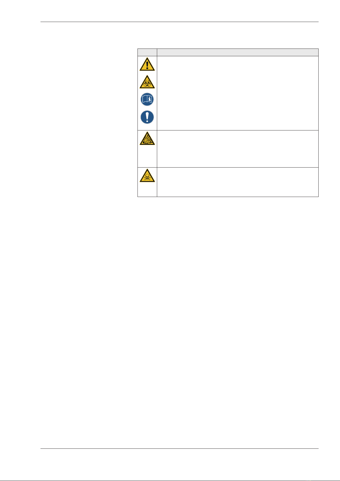
1.4 Explanation of Symbols 1..........................................................5
1.5 Explanation of Symbols 2..........................................................6
2 Basic Safety Information.....................................................................7
2.1 Standards and Directives...........................................................7
2.2 Intended Use ............................................................................7
2.3 Foreseeable Misuse...................................................................7
2.4 Personal Protective Equipment..................................................7
2.5 Hazards that may emanate from the System .............................8
2.6 Basic Safety Measures.............................................................10
2.7 Requirements on Specialist Personnel...................................... 11
3 Technical Data ................................................................................. 12
3.1 Features..................................................................................12
3.2 Specifications Booster Station .................................................12
3.3 Specifications Gas Booster ......................................................13
3.4 Fluid Diagram .........................................................................14
3.5 Dimension Drawing ................................................................15
3.6 Performance Graph ................................................................16
4 Commissioning the System .............................................................. 17
4.1 Safety Guidelines....................................................................17
4.2 Requirements on the Installation Location...............................18
4.3 Minimum clearance ................................................................18
4.4 Supply lines ............................................................................18
4.5 Operating materials ................................................................19
4.5.1 Drive Fluid ..................................................................19
4.5.2 Gas Quality ................................................................19
4.6 Valve adjustment ....................................................................19
4.7 Initial start-up and re-start / operation........................................19
5 Technical Description .......................................................................20
5.1 Essential Components.............................................................20
5.2 Connections ...........................................................................20
5.3 Operator Panel .......................................................................21
5.4 Functional Description ............................................................21
5.4.1 Drive Pressure Supply..................................................21
5.4.2 Fluid Supply / Gas Supply............................................22
5.4.3 Pressure Generation ...................................................22
5.4.4 Discharging ................................................................22

Friedrich Leutert GmbH & Co. KG 3
Booster Station - Operating Instructions
6 Service and Maintenance .................................................................23
6.1 Safety Information, Maintenance and Repair...........................23
6.2 Maintenance Intervals.............................................................23
7 Faults...............................................................................................24
7.1 Safety Guidelines....................................................................24
7.2 What to do in the Event of a Fault ..........................................24
7.3 What to do once the Fault has been removed.........................25
7.4 Faults, Causes and Remedies ..................................................25
7.4.1 Pressure Holding Test .................................................25
8 Spare Parts ......................................................................................26
8.1 Ordering Spare Parts...............................................................26
8.2 Returns / Complaints...............................................................26
9 Transport, Packaging and Storage ....................................................27
9.1 Transportation ........................................................................27
9.2 Packing Materials....................................................................29
9.3 Storage...................................................................................29
10 Dismantling and Disposal .................................................................30
10.1 Dismantling ............................................................................30
10.2 Waste Disposal .......................................................................30
11 Declaration of Conformity................................................................31
12 Parts List..........................................................................................32

4 Friedrich Leutert GmbH & Co. KG
Booster Station - Operating Instructions
1 Basic Information
1.1 Information about the Instructions
These instructions describe how to use the system safely and appropriately.
The safety information and instructions, as stated, must be complied
with. In addition, local occupational safety provisions and general safety
regulations apply to the area in which the system is used.
1.2 Other Applicable Documents
Components from other manufacturers are installed in the system.
These purchased assemblies have been subjected to a risk analysis by
the manufacturers. The manufacturers of the components have declared
that the designs are consistent with applicable European and national
regulations.
1.3 Warranty and Liability
In principle, the “General Terms and Conditions of Sale and Delivery”
submitted to the operating company by the manufacturer shall apply. Any
warranty and liability claims in the event of personal injury or material
damage are precluded if they are due to one or more of the following
causes:
•Improper use of the system.
•Incorrect commissioning, operation and maintenance of the system.
•Modifications of the system without the manufacturer’s prior
agreement.
•Operating the system with defective safety equipment or improperly
installed safety and protective equipment.
•Failure to comply with the information in these instructions in
respect of assembly, commissioning, operation and maintenance.
•Inadequate monitoring of system parts that are subject to wear and
tear.
•Improper repair work on the system or system parts.

Friedrich Leutert GmbH & Co. KG 5
Booster Station - Operating Instructions
1.4 Explanation of Symbols 1
Important safety information is marked by means of symbols in these
instructions. This information must be observed in order to avoid personal
injuries and material damage.
WARNING! Injury hazard or life-threatening hazard!
This symbol identifies information which, if not observed, may
result in an impairment of health, injuries, permanent physical
harm or even death and/or material damage.
WARNING! Electric shock hazard!
This symbol draws attention to hazardous situations caused by
electric currents. If the safety information is not observed, there is
a risk of serious injuries or death. Any work to be performed may
be carried out only by an instructed qualified electrician.
WARNING! Hazardous substances!
This symbol indicates environmental pollution or health risks
associated with the use of hazardous substances.
WARNING! Explosion hazard!
This symbol indicates a risk in the event of use in explosive
atmospheres.
WARNING! Toxic substances!
This symbol indicates a health hazard due to toxic substances or
accumulations of gases / vapours that may lead to unconsciousness
or adverse health effects.
WARNING! Flying particle hazard!
This symbol indicates a hazard due to flying particles.
NOTE about wearing personal protective equipment!
This symbol indicates a situation in which wearing appropriate
protective equipment is necessary.
NOTE about reading the documentation and data sheets!
This symbol indicates that the enclosed documents must be read.
Reference to additional information!
This symbol refers to useful additional information.

6 Friedrich Leutert GmbH & Co. KG
Booster Station - Operating Instructions
1.5 Explanation of Symbols 2
Important safety information is marked by means of symbols in these
instructions. This information must be observed in order to avoid personal
injuries and material damage.
Warning: Suspended load!
This symbol identifies a risk which, if not observed, may result in
an impairment of health, injuries, permanent physical harm or even
death and/or material damage.
Prohibition sign: No anchor points!
This symbol identifies a prohibited action which, if not observed,
may result in an impairment of health, injuries, permanent physical
harm or even death and/or material damage.
Observe advice about anchor points!
This symbol identifies information which, if not observed, may
result in an impairment of health, injuries, permanent physical
harm or even death and/or material damage.
Note: Use a stacker!
This symbol identifies information which, if not observed, may
result in an impairment of health, injuries, permanent physical
harm or even death and/or material damage.

Friedrich Leutert GmbH & Co. KG 7
Booster Station - Operating Instructions
2 Basic Safety Information
2.1 Standards and Directives
The system has been built in accordance with the current state of the art
and generally accepted safety rules. In designing the system, basic safety
requirements, as well as standards and directives, have been applied
in accordance with the declaration of conformity. All safety information
is based on currently applicable regulations issued by the European
Union. Apart from the safety information provided in these instructions,
the generally accepted rules of accident prevention and environmental
protection have been observed and complied with.
2.2 Intended Use
The Booster Station is used for boosting pressure in gas systems up to max.
1,300 bar and is intended for the following fluid: Nitrogen (N2)
It is solely designed for assembly with other machines to create a complete
machine. Operational safety is guaranteed only if the system is used
appropriately.
Appropriate use also includes compliance with the operating conditions, as
well as the information contained in these instructions.
2.3 Foreseeable Misuse
The system is designed for operating fluids according to the intended use.
Compliance with these instructions must be taken into account. Using
other fluids without first consulting the manufacturer is prohibited and
may cause personal injury and material damage.
Drive pressure > 10 bar, max. 20°C (PL)
Falling below or exceeding the operating temperatures -20 °C to 60°C
2.4 Personal Protective Equipment
In line with the risk assessment, the following protective clothing must be
worn:
•Gloves and protective goggles when carrying out maintenance
activities
•Protective goggles during initial start-up and re-start operations due
to possible leaks
•Wear a helmet when lifting loads

8 Friedrich Leutert GmbH & Co. KG
Booster Station - Operating Instructions
2.5 Hazards that may emanate from the System
The following section lists residual risks that may emanate from the system
even if it is used as intended.
Symbol Event Cause Note
Starting No restart protection
available
In the event of returning drive
energy (drive pressure), the
pressure generator starts to pump
and build up pressure depending
on the system configuration.
Energy supply fault
Normal stopping Primary pressure present,
or in the case of more
than one pressure
generator, the “second
stage” continues even
though the “first stage”
has been switched off.
Depending on system
configuration, the line pressure of
a mains-side fluid supply may be
present at the outlet even after
a pressure generator has been
switched off. Likewise, pressure
generators can operate in parallel,
resulting in pressure continuing
to be built up after one pressure
generator has been switched off.
Completeness of
machinery
Partly completed machinery, no interface for emergency-stop
circuit exists.
Noise No noise protection measures present; must be analyzed
during incorporation into the system as a whole (if necessary,
wear hearing protectors).
Vibrations Vibrations may occur; this must be analyzed during
incorporation into the system as a whole.
Emission of
hazardous
materials and
substances
Some hazardous
substances are present;
this must be analyzed
during incorporation into
the system as a whole.
Hazardous substances can also
be pumped depending on the unit
configuration.
Isolation of energy
sources
Primary pressure still
present
Pressure may be present at
the unit’s inlet, depending on
configuration.
Explosion Implementation
according to ATEX
Only systems with corresponding
labelling and with an enclosed
declaration of conformity in
compliance with the ATEX
Directive have been implemented
appropriately.

Friedrich Leutert GmbH & Co. KG 9
Booster Station - Operating Instructions
Symbol Note
Pneumatic and hydraulic energy can cause serious injuries.
If individual components are damaged, highly pressurized fluids may escape and
result in physical injury and/or material damage:
• Depressurize the system before beginning any work.
• Do not remove, modify or deactivate safety equipment.
• Do not modify pressure settings beyond the max. values indicated.
Flying particle hazard!
The system can be used to generate very high pressures. Therefore only use
attachment parts (adapters, hoses etc.) that have been approved for these pressure
ranges.
Asphyxiation hazard!
Nitrogen as a drive fluid displaces oxygen! When using nitrogen, ensure that there
is sufficient ventilation.

10 Friedrich Leutert GmbH & Co. KG
Booster Station - Operating Instructions
2.6 Basic Safety Measures
The following basic safety measures must be complied with:
•The system may be used only as intended.
•All safety information contained in these instructions and in all other
documentation must be observed and complied with.
•The system may be assembled, operated and serviced only by
trained and instructed specialist personnel. The specialist personnel
must have read and understood the instructions. This includes,
in particular, knowledge about how to avert risks of injury to the
operator and third parties.
•No unauthorized persons may have access to the system.
•All safety information contained in these operating instructions and
in all other documentation must be observed and complied with.
•Outages and adverse environmental impact due to incorrect
handling must be precluded.
•Basic specific protection measures for handling hazardous or
environmentally harmful fluids must be observed.
•The operating company must take steps to ensure compliance with
the occupational safety provisions in terms of oil and grease content
in released compressed air / drive fluid.
•All work on the system must be carried out carefully and with safety
in mind.
•The relevant regulations on occupational safety and environmental
protection must be observed during transportation, assembly and
dismantling, operation, maintenance and service work.
•Spare parts must always be obtained from LEUTERT. LEUTERT
accepts no liability for damage resulting from the use of spare parts
supplied by other manufacturers.

Friedrich Leutert GmbH & Co. KG 11
Booster Station - Operating Instructions
2.7 Requirements on Specialist Personnel
Prior to commencement of work, any hazards involved in using the system
must be pointed out to specialist personnel.
The system may pose injury hazards if not operated by trained and qualified
personnel.
Any specialist personnel instructed to commission, service or repair the
system must have read and understood the instructions in their entirety.
This also applies if the specialist personnel in question have already
operated, or received training for, the system.
The instructions must be available to the specialist personnel at all times.
We recommend that you obtain written confirmation from the specialist
personnel that they are familiar with the contents of the instructions.
The operating company or authorized specialist personnel that handle
the system in accordance with their operational duties are responsible for
ensuring accident-free operation.
To ensure safe handling of the system, specialist personnel are obliged to
observe the following instructions:
•Personnel are not permitted to work on the system if they are
overtired or under the influence of alcohol or medication.
•Specialist personnel must not have any physical limitations that
diminish their attentiveness or judgment, either temporarily or
permanently.
•Specialist personnel must wear protective clothing suited to the task
at hand.
•All safety information contained in these instructions and in all other
documents must be fully observed and complied with at all times.
•If hazards that might result in personal injury are identified, the
system must be shut.
Specialist personnel must have sound knowledge of the following
operational processes, regulations and practices:
•Operational system processes
•Danger zone demarcations, safeguards and markings
•Procedures to be followed and measures to be taken in the event of
danger

12 Friedrich Leutert GmbH & Co. KG
Booster Station - Operating Instructions
3 Technical Data
3.1 Features
•easy to operate
•compact construction style
•pneumatic drive
•automatic stop at endpressure
•automatic restart after pressure drop
•no electric energie required
•stationary
3.2 Specifications Booster Station
Type : DLE 75-1-2-GU-614 (4H)
Pressure ratio : 1:150
Outlet Pressure max. : 1,050 bar
Process fluid : Nitrogen
Flow max. : depending on application
Air pressure drive : min. 1 bar / max. 7 bar
Max. drive pressure PS : 10 bar
Max. operating pressure PS : 1,300 bar
Operating temperature TS : -20 °C to 60 °C
Dimension (W x D x H) : 650 mm x 260 mm x 410 mm
Weight : 34 kg
Connection values
Drive fluid inlet (PL) : 1/2” G / BSPf
Primary pressure inlet (A) : 1/4” NPTi
Pressure outlet (P) : 7/16 - 20 UNFi
Airborne noise emission
Must be analyzed in the system as a whole.

Friedrich Leutert GmbH & Co. KG 13
Booster Station - Operating Instructions
3.3 Specifications Gas Booster
Air drive pressure pL : 1 to 10 bar / 14.5 to 145 psi
Pressure ratio : 1:150
Compression ratio : 1:20
Min. suction pressure pA : 50 bar
Max. suction pressure pA : 1,500 bar
Max. outlet pressure pB : 1,500 bar
Displacement volume/double stroke : 25 cm³
Max. cycles : 120 / min
Stall pressure : PB = i * pL
Max. operating temperature : 100°C
Dimension (W x D x H) : 448 mm x 181 mm x 275 mm
Net weight : 20 kg

14 Friedrich Leutert GmbH & Co. KG
Booster Station - Operating Instructions
3.4 Fluid Diagram
9
10
Air Drive Pressure
Shut-off Valve Air DriveAir Drive Regulator
N2 Outlet Pressure
Stroke Counter
Pressure Relief Valve
N2 Inlet Pressure
3
2
13
11
1
6
4
7
S
X L R y2
y1
P
A
PL
12
Pos. Description Part-No.
1 Booster Station 3210.1021
2 Tee connector 1,500 bar 1/4“ 3780.0375
3 Pressure Gauge 0 to 1,600 bar ø 100 mm 3300.4678
4 2-Way-Angle-Valve 1,500 bar 3780.1635
6 Stroke counter 8-digit 3630.1002
7 Safety valve 7 bar 3620.2692
8 Operating panel 3300.1060
9 Shut-off valve G 1/2“ 3507.1030
10 Pressure gauge 0 to 16 bar ø 63 mm 3300.0468
11 Pressure gauge 0 to 250 bar ø 63 mm 3920.0696
12 Pressure regulator BSP 1/2“ 3630.0100
13 Filter 7 Mic. (G 1/4) 3630.1638
Legend:
Connections:
piping stainless steel 15L
PL Drive Pressure
1/2“ BSP
f
P Pressure Outlet
7/16 - 20“ UNF
i
A Fluid Inlet
1/4“ NPT
i
piping stainless steel 8S
piping stainless steel 4M
plastic hoses ø 16 mm
plastic hoses ø 10 mm
plastic hoses ø 6 mm
Safety Valve
Booster Station DLE 75-1-2-GU-614 (4H)
E
P1
00000000
pmax 10 bar / 145 psi
pmin 1 bar / 14.5 psi
Tmax 20°C / 68°F
pmax 1,300 bar / 18,850 psi
Tmax 60°C / 140°F
pmax 250 bar / 3,625 psi
pmin 50 bar / 725 psi
Tmax 20°C / 68°F

Friedrich Leutert GmbH & Co. KG 15
Booster Station - Operating Instructions
3.5 Dimension Drawing
"Z3"
High pressure drain port 1/8 BSP
"Z4"
Air drive drain port 1/8 BSP
"SFP"
Special flushing port 1/8 BSP
Air release spool valve Drain port 1/8 BSP Pilot valve air release connection M5
Z3 Z4 SFP
X
Exhaust connection 1/2 BSP
392.5
170
11
4
80
54
13
587
619
233
181
143
131
135.5
200.5
88
A - Gas inlet 1/4 BSP
B - Gas outlet 9/16-18UNF (4H)*
*HP-Tube Connection: 4H (1/4" 65000psi / 4500bar) turned mounting bracket on the top cap
A
"PL"
Air drive inlet 3/4 BSP
"X"
External pilot connection 1/8 BSP
Booster Type DLE 75-1-2-GU-614
Pressure ratio : 1:150
Inlet Pressure : 50 bar / 725 psi
Outlet pressure : 1,500 bar / 21,750 psi
Drive pressure : 10 bar / 145 psi

16 Friedrich Leutert GmbH & Co. KG
Booster Station - Operating Instructions
MAXIMATOR GmbH, Lange Strasse 6, 99734 Nordhausen, Telephone +49 3631 9533 – 0, Telefax +49 3631 9533 – 5010, www.maximator.de, info@maximator.de
High Pressure Technology • Testing Equipment
Hydraulics • Pneumatics
Maximum Pressure.
0
20
40
60
80
100
120
140
160
0
100
200
300
400
500
600
0
200
400
600
800
1000
1200
1400
Max. Outlet Pressure 1500 bar
Pv = 35 bar
Pv = 80 bar
Pv = 100 bar
Pv = 50 bar
0
20
40
60
80
100
120
140
160
180
200
0
100
200
300
400
500
600
700
800
900
0
200
400
600
800
1000
1200
1400
1600
1800
2000
Max. Outlet Pressure 1500 bar
Pv = 40 bar
Pv = 100 ba r
Pv = 120 ba r
Pv = 70 bar
0
50
100
150
200
250
0
100
200
300
400
500
600
700
800
900
1000
1100
1200
0
500
1000
1500
2000
2500
3000
Max. Outlet Pressure 1500 bar
Pv = 40 bar
Pv = 100 bar
Pv = 150 bar
Pv = 70 bar
3.6 Performance Graph

Friedrich Leutert GmbH & Co. KG 17
Booster Station - Operating Instructions
4 Commissioning the System
4.1 Safety Guidelines
Check that components are complete and in perfect technical condition
and read the instructions as well as connection diagram and data sheets
before setting the system up and installing it.
Only personnel with the relevant qualifications may assemble and install
the system.
General accident prevention measures should be borne in mind before
commissioning and filling the system; personal protective equipment (PPE)
comprising protective goggles and gloves should also be worn.
Only use materials that have been approved for the fluid used and the
pressure range in line with these instructions, connection diagram and
intended use.
Damaged or unsuitable materials may cause serious physical injury and/or
material damage!

18 Friedrich Leutert GmbH & Co. KG
Booster Station - Operating Instructions
4.2 Requirements on the Installation Location
The system can be installed both inside and outside buildings (protected
from the weather).
Steps must be taken to ensure adequate ventilation or monitoring at
the installation site, in particular with respect to systems for hazardous
or environmentally harmful fluids. Steps must be taken to ensure safe
discharge of leak and relief lines.
The installation surface must be flat and free of contamination and have
sufficient stability or load capacity. The system is designed for use in the
following atmospheric conditions:
Temperature range : 5 °C to 40 °C
Relative humidity : max. 60 %
Ambient pressure range : min. 1 bar less than the drive pressure
4.3 Minimum clearance
For operation and maintenance purposes, the system must be installed
with sufficient clearance from walls, ceilings and other devices. Free access
to the system must be possible at all times. For guide values for premises,
see DIN EN547-1 and DIN EN547-3.
4.4 Supply lines
Install the supply lines required to operate the system in accordance with
the applicable provisions and safety regulations.
Remove the factory sealing caps before connecting the supply lines. For
the required connection dimensions, see the enclosed fluid diagram and
section 3 “Technical Data“ in these instructions.
Supply lines on site need to be equipped with shutoff fittings to facilitate
service and maintenance activities. Furthermore, steps need to be taken on
site to ensure that the pumping rates of upstream pressure generators do
not exceed the maximum discharge rate of installed safety valves.
Connections for safety valves need to be connected and implemented on
site in accordance with AD2000.

Friedrich Leutert GmbH & Co. KG 19
Booster Station - Operating Instructions
4.5 Operating materials
Compressed air and the fluid to be boosted as defined in the system
specification are required to operate the system.
These operating materials must be provided on-site by the operating
company.
4.5.1 Drive Fluid
The drive air should exhibit the following quality classes as defined in
ISO8573-1:
Solids: class 6: max. particle size: 5 μm
Max. particle concentration: 5 mg/m³
Pressure dew point: class 7: 10 °C water content of max. 5 g/m³
Oil content: class 4: ≤ 5 mg/m³
4.5.2 Gas Quality
Solids: max. particle size: 10 μm
Max. inlet temperature: 20 °C
The specified fluid quality ensures that seals and guide elements have an
optimum lifetime.
4.6 Valve adjustment
Prior to initial start-up, check the adjustment of the shut-off valves and set
them to the closed position, if necessary.
When the system is delivered, relief valves are always open and
need to be closed for commissioning!
4.7 Initial start-up and re-start / operation
When starting up and re-starting the system after an extended standstill,
take particular care to ensure that it is started up slowly. To ensure this, you
will need to increase the drive pressure slowly.
The pressure generators should carry out several strokes with the relief
valve open and with low drive and/or primary pressure.

20 Friedrich Leutert GmbH & Co. KG
Booster Station - Operating Instructions
5 Technical Description
5.1 Essential Components
The item information/designations in these instructions are consistent with
those in the fluid diagram.
5.2 Connections
The item information/designations in these instructions are consistent with
those in the fluid diagram.
Pressure outlet (P)
Primary pressure inlet (A) Air drive inlet (PL)
Handle
Compressor Drive air filter Pre-pressure filter
Control panel
This manual suits for next models
5
Table of contents
Popular Laboratory Equipment manuals by other brands

Elisabeth Pharmacon
Elisabeth Pharmacon ZEPHYRUS GelCube Illuminator Series Instructions for use

Retsch
Retsch SM100 operating manual

Exsys
Exsys EX-60300 manual

IKA
IKA KS 4000 i control operating instructions

Sanuvox
Sanuvox SABER MAGNET instruction manual

Heathrow Scientific
Heathrow Scientific Sprout Plus instruction manual

Elmi
Elmi DOS-10L user manual

Thermo Scientific
Thermo Scientific Apreo User's operation manual

IKA
IKA ULTRA-TURRAX T 25 digital operating instructions

sterilAir
sterilAir T2018 Series operating manual

Analytik Jena
Analytik Jena CyBio Well vario OL3381-25-300 operating manual

Gilson
Gilson PIPETMAN 8X200 user manual