Leuze electronic BCL 21/22 3
Leuze electronic Figures and tables
Figure 2.1: Attachment of the sticky labels with warning notices at the BCL 21/22 ....................... 8
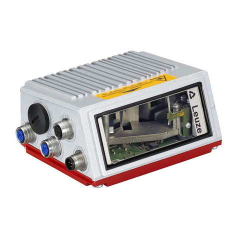
Figure 3.1: BCL 21/22 device construction.....................................................................................9
Figure 3.2: Networking possibilities using the multiNet plus (BCL 21) ......................................... 10
Table 4.1: General Specifications ...............................................................................................12
Table 4.2: LED indicators ............................................................................................................13
Figure 4.1: Dimensioned drawingBCL 21/22................................................................................ 14
Figure 4.2: Type key BCL 21/22...................................................................................................15
Table 4.3: Overview of the BCL 21 types.................................................................................... 17
Table 4.4: Overview of the BCL 22 types.................................................................................... 19
Figure 4.3: Reading field, optics model N (high density) ..............................................................20
Figure 4.4: Reading field, optics model M (medium density, normal range) ................................20
Figure 4.5: Reading field, optics model F (low density, long range).............................................21
Table 5.1: BCL 21 accessories ...................................................................................................22
Table 5.2: BCL 22 accessories ...................................................................................................23
Figure 5.1: Connector unit MA 2...................................................................................................24
Figure 5.2: Dimensioned drawing connector unit MA 2................................................................25
Figure 5.3: Connector unit MA 4/MA 4D....................................................................................... 26
Figure 5.4: Dimensioned drawing connector unit MA 4/MA 4D....................................................27
Figure 5.5: Connector unit MA 4 1xx/MA 4 D 1xx ........................................................................ 28
Figure 5.6: Dimensioned drawing MA 4 1xx/MA 4 D 1xx ............................................................. 29
Figure 5.7: Mounting device BT 20............................................................................................... 30
Figure 5.8: Mounting device BT 21............................................................................................... 30
Figure 6.1: Device name plate BCL 21/22.................................................................................... 31
Figure 6.2: Mounting example BCL 21/22 ....................................................................................32
Figure 6.3: Applications with perpendicular and front side beam exit ..........................................33
Figure 6.4: BCL 21/22 Sub-D pin assignments ............................................................................ 34
Table 6.1: Wiring description BCL 21..........................................................................................35
Table 6.2: Wiring description BCL 22..........................................................................................35
Figure 6.5: BCL 21 with connector unit MA 2/MA 4… ..................................................................36
Figure 6.6: Connector unit MA 2...................................................................................................37
Table 6.3: Terminal assignment MA 2......................................................................................... 37
Table 6.4: Terminal assignment voltage supply .......................................................................... 38
Table 6.5: Terminal assignment switching inputs........................................................................38
Table 6.6: Terminal assignment switching outputs ..................................................................... 38
Figure 6.7: Circuitry MA 2............................................................................................................. 39
Figure 6.8: Connector unit MA 4/MA 4D....................................................................................... 39
Table 6.7: Terminal assignment MA 4/MA 4D............................................................................. 40
Table 6.8: Terminal assignment voltage supply .......................................................................... 40
Table 6.9: Terminal assignment switching inputs........................................................................41
Table 6.10: Terminal assignment switching outputs ..................................................................... 41
Figure 6.9: Circuitry MA 4/MA 4D................................................................................................. 42
Figure 6.10: Connector unit MA 4 1xx/MA 4 D 1xx ........................................................................43
Table 6.11: Terminal assignment MA 4 1xx/MA 4 D 1xx ..............................................................43
Table 6.12: Terminal assignment voltage supply .......................................................................... 44
Table 6.13: Terminal assignment switching inputs........................................................................44
Table 6.14: Terminal assignment switching outputs ..................................................................... 45
Figure 6.11: Circuitry MA 4 1xx/MA 4 D 1xx................................................................................... 45
Table 6.15: Wire Lengths and Shielding .......................................................................................46


