Leuze electronic BCL 8 3
Figures and tables
Figure 2.1: Laser apertures, laser warning signs ...........................................................................9
Figure 2.2: Laser warning and laser information signs – supplied stick-on labels........................ 10
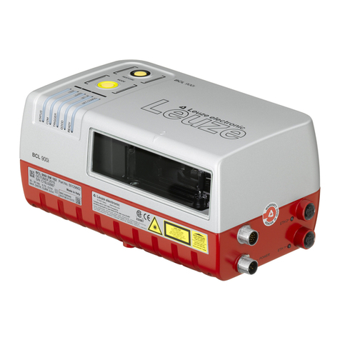
Figure 3.1: Device construction of the BCL 8 ............................................................................... 11
Table 4.1: Technical Data ........................................................................................................... 13
Table 4.2: LED indicators ............................................................................................................ 14
Figure 4.1: Dimensioned drawing BCL 8 S M …0, BCL 8 S N …0 with lateral beam exit ...........15
Figure 4.2: Dimensioned drawing BCL 8 S M …2, BCL 8 S N …2 with front beam exit .............. 16
Table 4.3: Type overview - M-optics ........................................................................................... 17
Table 4.4: Type overview - N-optics............................................................................................ 17
Figure 4.3: Reading field of BCL 8 S M … with M-optics (medium density).................................18
Figure 4.4: Reading field of BCL 8 S N … with N-optics (high density)........................................ 19
Table 5.1: Accessories / order codes .......................................................................................... 20
Figure 5.1: Photo and dimensioned drawing of the MA 8.1 connector unit .................................. 21
Figure 5.2: Electrical connection MA 8.1 ...................................................................................... 22
Figure 5.1: MA 8.1 - Pin assignment PWR IN HOST/RS 232 ...................................................... 23
Figure 5.1: MA 8.1 - Pin assignment SW IN/OUT ........................................................................ 23
Figure 5.2: Connection of the switching input/output of the MA 8.1 ............................................. 24
Figure 5.1: MA 8.1 - Pin assignment BCL .................................................................................... 25
Figure 5.2: Pin assignment MA 8-01 ............................................................................................ 26
Figure 5.1: MA 8-01 - Pin assignment PWR IN HOST/RS 485 .................................................... 27
Figure 5.1: MA 8-01 - Pin assignment SW IN/OUT ...................................................................... 28
Figure 5.2: Electrical connection MA 8-01....................................................................................29
Figure 5.1: MA 8-01 - Pin assignment BCL .................................................................................. 29
Figure 5.2: Termination of the RS 485 interface in the MA 8-01 .................................................. 30
Figure 5.3: Universal rod mounting system for BCL 8.................................................................. 31
Figure 6.1: BCL 8 device name plate ........................................................................................... 32
Figure 6.2: Definition of the BCL 8 reading angles....................................................................... 34
Figure 6.3: BCL 8 pin assignment ................................................................................................ 35
Table 6.1: Wiring description BCL 8............................................................................................ 35
Figure 6.4: Switching input for BCL 8 connection version 1 (standard setting) ............................36
Figure 6.5: Switching input for BCL 8 connection version 2 (setting "inverted")........................... 36
Figure 6.6: Switching output BCL 8 .............................................................................................. 37
Table 6.2: Line lengths ................................................................................................................38
Figure 7.1: Bar code label "Service".............................................................................................41
Figure 7.2: Connecting the RS 232 interface to a PC or terminal ................................................ 41
Figure 9.1: Installation window ..................................................................................................... 44
Figure 9.2: Installation directory ................................................................................................... 45
Figure 9.3: BCL 8 configuration software ..................................................................................... 45
Figure 10.1: Decode tab ................................................................................................................. 46
Figure 10.2: Standard settings for the Properties window – Decode tab ....................................... 47
Figure 10.3: Output tab................................................................................................................... 48
Figure 10.4: Control tab.................................................................................................................. 49
Figure 10.5: Host interface tab ....................................................................................................... 50
Figure 10.6: Standard settings for the Properties window – Host interface tab.............................. 51
Figure 10.7: Reference code tab .................................................................................................... 52
Figure 10.8: Sensor tab .................................................................................................................. 53
Figure 10.9: Laser tab .................................................................................................................... 54
Figure 10.10: AutoReflAct Wizard .................................................................................................... 55
Figure 10.11: Switch tab................................................................................................................... 56
Figure 12.1: Example bar code label types .................................................................................... 71


