4 BCL 34 Leuze electronic
Figures and tables Leuzeelectronic
Figure 2.1: Attachment of the sticky labels with warning notices at the BCL 34 ............................9
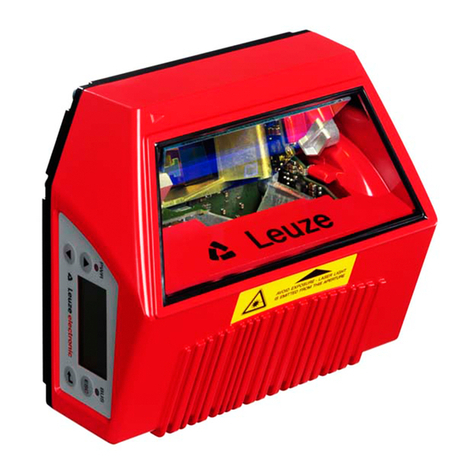
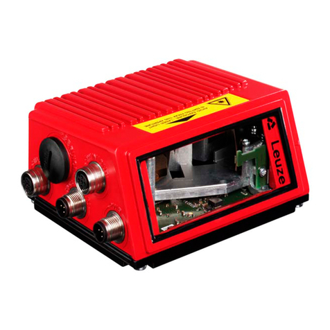
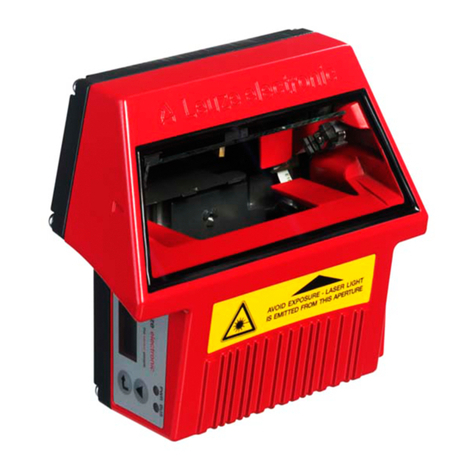
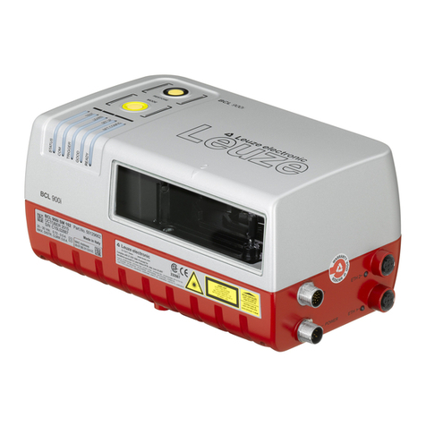
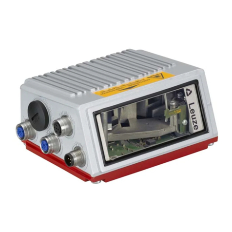
Figure 3.1: BCL 34 device construction........................................................................................10
Table 4.1: General Specifications ...............................................................................................13
Table 4.2: LED states MS 34 103 / MS 34 105...........................................................................13
Figure 4.1: BCL 34 with MS 34 105..............................................................................................14
Figure 4.2: Dimensioned drawing BCL 34....................................................................................14
Figure 4.3: Dimensioned drawing MS 34 103 / MS 34 105..........................................................15
Table 4.3: Type overview BCL 34 without integrated heating.....................................................16
Table 4.4: Type overview BCL 34 with integrated heating..........................................................16
Figure 4.4: BCL 34…100: Reading field, M optics (medium density, normal distance) ...............17
Figure 4.5: BCL 34…100: Reading field, F optics (low density, normal distance)........................18
Figure 4.6: BCL 34…100: Reading field, L optics (low density, long distance)............................18
Figure 4.7: BCL 34…100: Reading field, J optics (for ink-jet applications) ..................................19
Figure 4.8: BCL 34…100 H: Reading field, M optics (medium density, normal distance)............20
Figure 4.9: BCL 34…100 H: Reading field, F optics (low density, normal distance)....................20
Figure 4.10: BCL 34…100 H: Reading field, L optics (low density, long distance) ........................21
Figure 4.11: BCL 34…100 H: Reading field, J optics (for ink-jet applications)...............................22
Table 4.5: Examples of reflectors which may be used................................................................23
Figure 4.12: Reflector arrangement for autoReflAct.......................................................................23
Table 5.1: Accessories / Order Designation................................................................................24
Figure 5.1: Modular Service Display MSD 1 101..........................................................................25
Figure 5.2: Mounting device BT 56...............................................................................................26
Figure 6.1: Device name plate BCL 34.........................................................................................27
Figure 6.2: Mounting example BCL 34.........................................................................................28
Figure 6.3: Beam outlet on the BCL 34........................................................................................29
Figure 6.4: Application example "conveyor chain" .......................................................................30
Figure 6.5: View of the inside of the MS 34..................................................................................31
Figure 6.6: Connection assignment of the BCL 34 with MS 34 103 / MS 34 105.........................32
Table 6.1: Pin assignment PWR IN.............................................................................................33
Table 6.2: Pin assignment SW IN/OUT.......................................................................................33
Table 6.3: Pin assignment DP IN/OUT........................................................................................34
Figure 6.7: Mounting Profibus Connector.....................................................................................35
Figure 6.8: Connection diagram switching inputs and outputs BCL 34........................................36
Table 7.1: "Common" Parameters...............................................................................................39
Table 7.2: Code type and code length, Tables 1-4 .....................................................................39
Table 7.3: Overview of the project modules................................................................................40
Table 7.4: Parameters for Modules 1-4.......................................................................................42
Table 7.5: Parameters for Module 5............................................................................................43
Table 7.6: Input data for Module 5 ..............................................................................................43
Table 7.7: Output data module 5.................................................................................................44
Table 7.8: Parameters for Module 6............................................................................................44
Table 7.9: Parameters for Module 7............................................................................................45
Table 7.10: Parameters for Module 8............................................................................................46
Figure 7.1: Specifying switch-on and switch-off positions of the laser .........................................47
Table 7.11: Parameters for Module 10..........................................................................................47
Table 7.12: Parameters for Module 10..........................................................................................48
Table 7.13: Parameters for Module 11..........................................................................................49
Table 7.14: Parameters for Module 12..........................................................................................50
