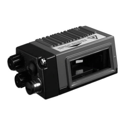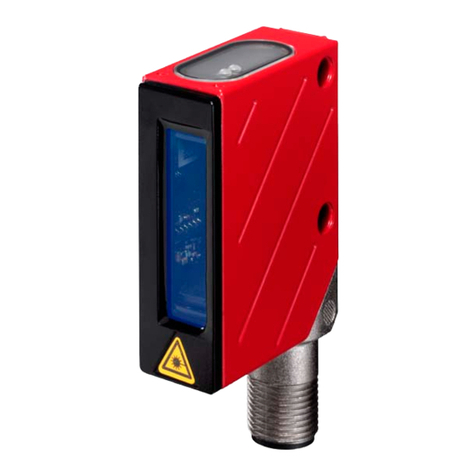
Leuze electronic BCL 558i7
Figures and tables
Figure 5.27: "Low Density" reading field curve for line scanner with heating (with deflection mirror) ........ 61
Figure 5.28: "Low Density" reading field curve for oscillating-mirror scanners with heating...................... 62
Figure 5.29: Lateral "Low Density" reading field curve for oscillating-mirror scanners with heating.......... 62
Figure 5.30: "Ultra Low Density" reading field curve for line scanner with heating (without deflection mirror) . 63
Figure 5.31: "Ultra Low Density" reading field curve for oscillating-mirror scanners with heating ............. 64
Figure 5.32: Lateral "Ultra Low Density" reading field curve for oscillating-mirror scanners with heating.. 64
Figure 6.1: Device name plate BCL 558i................................................................................................. 65
Figure 6.2: Fastening options using M4x6 threaded holes....................................................................... 66
Figure 6.3: BT 56 mounting device ......................................................................................................... 67
Figure 6.4: Mounting example of BCL 558iwith BT 56............................................................................ 68
Figure 6.5: BT 59 mounting device ......................................................................................................... 69
Figure 6.6: Total reflection – line scanner ............................................................................................... 71
Figure 6.7: Total reflection – BCL 558iwith oscillating/deflection mirror ................................................. 72
Figure 6.8: Reading angle for the line scanner ........................................................................................ 73
Figure 7.1: Location of the electrical connections.................................................................................... 74
Figure 7.2: Connections of the BCL 558i................................................................................................. 76
Table 7.1: Pin assignment PWR ............................................................................................................. 77
Figure 7.3: Switching input connection diagram SWIO_3 and SWIO_4 .................................................... 78
Figure 7.4: Switching output connection diagram SWIO_3 / SWIO_4....................................................... 78
Table 7.2: Pin assignments of SERVICE – USB interface......................................................................... 79
Table 7.3: Pin assignment SW IN/OUT ................................................................................................... 80
Figure 7.5: Switching input connection diagram SWIO_1 and SWIO_2 .................................................... 80
Figure 7.6: Switching output connection diagram SWIO_1 / SWIO_2....................................................... 81
Table 7.4: Pin assignment HOST / BUS IN BCL 558i............................................................................... 82
Figure 7.7: HOST / BUS IN cable assignments on RJ-45.......................................................................... 82
Table 7.5: Pin assignment BUS OUT ...................................................................................................... 83
Figure 7.8: Ethernet with star topology.................................................................................................... 84
Figure 7.9: Ethernet with linear topology................................................................................................. 84
Table 7.6: Cable lengths and shielding .................................................................................................. 85
Figure 8.1: Structure of the control panel................................................................................................ 86
Table 8.1: Parameter handling submenu ............................................................................................... 92
Table 8.2: Decoder table submenu ........................................................................................................ 93
Table 8.3: Digital SWIO submenu........................................................................................................... 96
Table 8.4: EtherNet/IP submenu ............................................................................................................ 99
Figure 9.1: Connecting the SERVICE USB interface................................................................................ 104
Figure 9.2: Device Manager with connected BCL 558i.......................................................................... 106
Figure 9.3: The start page of the webConfig tool................................................................................... 107
Figure 9.4: Module overview in the webConfig tool ............................................................................... 108
Figure 10.1: Connections of the BCL 558i............................................................................................... 111
Figure 10.2: Manually setting the IP address........................................................................................... 113
Figure 10.3: Generic Ethernet module..................................................................................................... 115
Figure 10.4: New module........................................................................................................................ 116
Figure 10.5: Connection between Data acceptance/Data rejection/Error code attributes.......................... 133
Figure 10.6: Configuration of example 1 - module definition with generic module................................... 137
Figure 10.7: Configuration of example 1 - module definition with the EDS file ......................................... 137
Figure 10.8: Data exchange sequence diagram - example 1 ................................................................... 139
Figure 10.9: Configuration of example 2 - module definition with generic module................................... 140
Figure 10.10: Configuration of example 2 - module definition with the EDS file......................................... 140
