manuals.online logo
Brands
  1. Home
  2. •
  3. Brands
  4. •
  5. Leviton
  6. •
  7. Accessories
  8. •
  9. Leviton Lumina ZSC15 User manual

Leviton Lumina ZSC15 User manual

Lumina™ RF Wireless Occupancy Sensor
Cat. Nos. ZSC04 & ZSC15
INSTALLATION AND QUICK START SHEET ENGLISH
DI-002-ZSCXX-00A
LEVITON LUMINA™ RF WALL SWITCH OVERVIEW
The Lumina™ RF components are designed to communicate with each other via 2.4GHz
Radio Frequency (RF) to provide remote control of your lighting. Each module in the
Lumina™ RF component line is designed to act as part of a system. Line powered
devices are designed to act as a router. These routers will re-transmit the RF signal from
one device to another until the intended device is reached. This ensures that the signal
is received by its intended device by routing the signal around obstacles and radio dead
spots.
DESCRIPTION
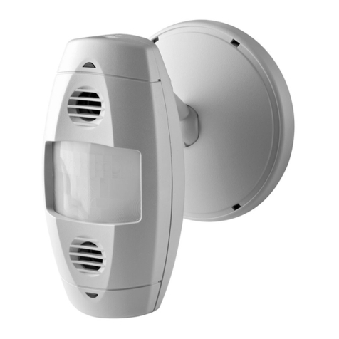
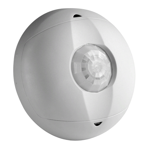
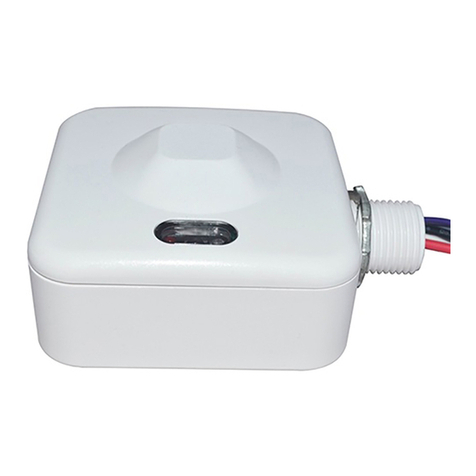
The Occupancy Sensor is a 2.4GHz wireless communication device which transmits a
wireless message to the Lumina™ gateway. This communication occurs each time an
occupancy change occurs in a room, occupied to unoccupied or unoccupied to occupied.
The gateway then routes the message to the load control device to take assigned action.
Occupancy/Vacancy time delays are configured and maintained in the gateway and load
control devices; this improves the design and efficiency of the wireless system.
QUICK START: SETUP, PROGRAMMING AND ACTIVATION
NOTE: Remove "Battery Pull Tab" to activate device.
Make sure the sensor is within 16 feet (5 meters) of the desired receiver when
programming.
• Configure the Lumina™ RF occupancy sensor using a Lumina™ gateway with a PC
running the Lumina™ RF smart configuration software
(see configuration videos and
software for detailed radio frequency pairing and control programming online at
www.leviton.com/luminarf). The device must be in Network Enrollment mode while
the Lumina™ gateway is searching for new devices to Enroll (see TABLE 2, MODE 1).
• Occupancy Sensor Programming: To associate a sensor with the receiving device
(gateway or other coordinator), remove the front access cover and use the MENU
button to enter the menu and enroll into a network (See TABLE 2, MODE 1 and the
Lumina™ gateway manual for details). Occupancy time delays are configured in
gateway or coordinator control device.
•
Gateway Activation: Once the Occupancy Sensor has been associated with a gateway/
coordinator, that device can then specify which loads to turn ON or OFF each time the
sensor’s field of view is entered (see configuration videos and software for detailed radio
frequency pairing and control programming online at www.leviton.com/luminarf).
OPERATION
LED Indicator (See TABLE 2, MODE 4)
The Lumina™ RF occupancy sensor comes equipped with an LED indicator that normally
flashes red for correct occupancy operation. This LED is also used during programming for
Menu and Mode selection.
• RED: PIR Motion detection (normal operation mode)
• AMBER: Signal to release push button when in Menu Mode
• GREEN: Represents a Menu mode or an active menu state (attempting to join a
network, identifying on the network, etc.)
OPERATION TESTING
1. Once joined into a network, confirm occupancy detection (RED LED will blink), then
cover the occupancy sensor so no further detection is detected.
a. Verify timeout and load turns OFF accurately
2. Uncover the occupancy sensor to verify Auto-ON responds and energizes load(s).
FIELD OF VIEW & SENSITIVITY TESTING
• Perform a FOV walk test of the coverage area and confirm the RED LED blinks and
detects within the responsible space (See TABLE 3).
• Adjust the sensitivity POT as necessary to increase or decrease the detection sensitivity
within the field of view.
PIR SENSITIVITY ADJUSTMENT: This can increase or decrease the amount of detection
points within the specified field of view. This does not increase or decrease the range of the
PIR detection.
INSTALLATION
Do not mount the sensor until after it has been programmed to communicate with all
appropriate receivers. Equipment needed for installation:
• Ceiling Tile Stem, Nut, & Washer (included)
• Double Sided Foam Mounting Tape (included)
• Screws (included) with Wall Anchors (not included)
COMPATIBLE DEVICES
• Lumina™ gateway (required for ZSC04 & ZSC15 operation)
• Lumina™ 10A Decora®Wall Switch
NOTES
•
Requires Lumina™ gateway for programming and control communication to other devices.
• Do not mount the sensor until after it has been programmed to communicate with all
appropriate receivers.
WARNINGS AND CAUTIONS
•
TO AVOID SERIOUS PERSONAL INJURY, DO NOT RECHARGE, DISASSEMBLE OR INCINERATE BATTERY, NOR HEAT IT ABOVE 100° C (212° F).
Dispose of used battery promptly. DO NOT dispose of battery in normal household waste. Keep away from children. Please contact your local waste
provider or recycling facility for proper disposal of used battery.
• Replace battery with Panasonic, Energizer, Sony, Duracell, Rayovac or Maxell CR2450 only. Use of another battery may present a risk of fire or explosion.
• To be installed and/or used in accordance with appropriate electrical codes and regulations.
• If you are unsure about any part of these instructions, consult an electrician.
• For indoor applications only.
• Save these instructions.
CEILING TILE MOUNT
1. Use the included ceiling tile stem, connect the stem to the back cover and twist to
secure, reference figures below for details.
2. In desired location, press the ceiling tile stem through the ceiling tile and install the
washer and nut above the ceiling tile to secure.
NOTE: The sensor back cover and front body are keyed with arrows for ease of
separation. To lock the sensor body to the back cover, align arrows and press
back cover to the front body, then rotate until the arrows are not aligned.
3. Rotate the sensor to the desired orientation.
Sensor location
optimized for best
entry detection and
reduced nuisance
tripping from hallway
Sensor location
center of room has
potential risk of
nuisance tripping
from hallway traffic
Drop Ceiling
1" thick maximum Nut Washer
Tile Stem
Mounting Option Diagram A
Sensor Mounted to Drop Ceiling Using Tile Stem
SURFACE MOUNT USING SCREWS
1. To remove the back cover of the sensor, locate alignment arrow on the edge of the back
cover and on the edge of the front body, rotate the back cover and front body until the
two arrows line up and pull apart.
2. Install back cover of the ceiling sensor to desired location using the included screws
(nuts and washers), or screws in combination with commercially available wall anchors.
If necessary, drill pilot holes.
3. Secure the sensor body to the back cover by aligning the arrows. Lock it by turning the
sensor such that the arrows do not line up.
4. Rotate the sensor to the desired orientation.
Nut
Washer
Sensor Back
Cover
Mounting
Screw
Mounting
Screw
Sensor Base
Back Cover shown mounted
to ceiling with screws
Back Cover (inside)
Sensor Front
Cover
Key lock
Arrow
Wallboard
Ceiling
Mounting Option Diagram B
Sensor Mounted to Wallboard or Drop Ceiling Using Screws
SURFACE MOUNT USING TAPE
1. Remove backing material and apply double sided mounting tape to the Sensor Base.
2. Press and hold the Wireless Occupancy Sensor to the desired mounting surface for a
few seconds before releasing. NOTE: The sensor back cover and front body are keyed
with arrows for ease of separation. To lock the sensor body to the back cover, align ar-
rows and press back cover to the front body, then rotate until the arrows are not aligned.
3. Rotate the sensor to the desired orientation.
Location: (Choose location to mount the sensor and the appropriate method -
Tile Stem, Screws, Mounting Tape)
1.
Sensor location is very important to ensure correct operation within each unique space.
2. Improve performance to Auto-ON response and reduce risk of false tripping from
external motion (example: hallway traffic) by choosing the best location.
3. Do not locate a sensor on a mounting surface within 6 feet of - air ducts, moving
machinery, heat sources.
TABLE 1 - Operation Modes Defined
Mode /
Blink(s) Operation
1Enrollment - Allows the device to enroll in a network, and be removed.
2Identify - The device will announce itself to other devices in the network.
3Walk Test - The device shortens the blackout and occupancy detection periods
to 2 seconds. This mode Auto Exits after 3 minutes.
4LED Operation - Allows the device to enable/disable LED operations.
5Reset - Resets device to Factory Default settings.
TABLE 2 - Configuration Menu, Quick Start Programming
Notes
Requires LuminaTM gateway - Review all related gateway instructions before
beginning.
Idle Time Exit: No button presses for > 20 seconds will time out the menu and
return to normal operation.
Mode 1: Enrolling your Device in RF Network
Enter
Menu
Press and hold the Menu button for > 10 seconds - identified by the LED
switching to rapid green blinking (Mode 1 - One Blink - Enroll into LuminaTM RF
Network).
Add
Device
Press and hold the Menu button for > 5 seconds to enroll into LuminaTM RF net-
work. Rapid green blinking continues until device is enrolled. Upon completion,
device returns to Menu selection.
Review Review LuminaTM gateway instructions. Power up gateway and prepare net-
work.
Exit Tap Menu button (<3s) to go back to menu selection. Alternative option is to
wait 20 seconds for auto exit timeout.
Mode 2: Identify a Device
Enter
Menu
Press and hold the Menu button for >10 seconds - identified by the LED
switching to rapid green blinking (Mode 1 - One Blink - Enroll into LuminaTM RF
Network).
Step 1 Tap (< 3 seconds) Menu button 1 time to move into Two Blink (Mode 2 - Identify
Operation).
Identify
Device
Press and hold the Menu button for >5 seconds to enter Identify Device Mode.
Rapid green blinking continues until identify time is complete.
Exit Will auto exit after 60 seconds.
Mode 4: Turn LED OFF/ON
Enter
Menu
Press and hold the Menu button for > 10 seconds - identified by the LED
switching to rapid green blinking (Mode 1 - One Blink - Enroll into LuminaTM RF
Network).
Step 1 Tap (< 3 seconds) Menu button 3 times to move into Four Blink
(Mode 4 - LED Operation).
Step 2 Press and hold Menu button for > 3 seconds to toggle the LED mode
-
Green LED confirmation blink indicates locator LED will operate normally
- Red LED confirmation blink indicates locator LED will be disabled and remain
OFF.
Exit Tap Menu button (< 3 seconds) to go back to the menu selection. Alternative
option is to wait 20 seconds for auto exit timeout.
TABLE 3 - Field of View Walk Test Operation Mode 3
Enter
Menu
Press and hold the Menu button for >10 seconds - identified by the LED
switching to rapid green blinking (Mode 1 - One Blink - Enroll into LuminaTM RF
Network).
Step 1 Tap (< 3 seconds) Menu button 2 times to move into Three Blink
(Mode 3 - Walk Test Operation).
Walk
Test
Press and hold the Menu button for >5 seconds to enter Walk Test Mode. Walk
test time is for 3 minutes. Field of view testing is done by walking the perimeter,
entry points, and directly toward the sensor (NOTE: When in this mode, the
device shortens the blackout and occupancy detection periods to 2 seconds).
Exit Tap Menu button (<3s) to go back to menu selection. Alternative option is to
wait 20 seconds for auto exit timeout.
TABLE 4 - Configuration Menu: Reset to Factory Default Settings Mode 5
Enter
Menu
Press and hold the Menu button for >10 seconds - identified by the LED
switching to rapid green blinking (Mode 1 - One Blink - Enroll into LuminaTM RF
Network).
Step 1 Tap (< 3 seconds) Menu button 4 times to move into Five Blink
(Mode 5 - Reset).
Step 2
Press and hold the Menu button for >5 seconds to enter Factory Default
pending mode (Start red blinking - to cancel Reset: press the Menu button or
allow idle timeout).
Step 3:
Reset/
Exit
Press and hold the Menu button for >5 seconds to enter Factory Default Reset
process (Stops the red blinking, cancels the menu and returns to normal device
operation when reset is complete.
SPECIFICATIONS
Field of View (FOV) ZSC04 = 450 sq. ft.
ZSC15 = 1,500 sq. ft.
Frequency/Range 2.4 GHz/50-150 ft.
Operational Temperature 0° to 40° C
Power Supply CR2450 battery, 620mAh
Power Consumption < 10uA @ 3VDC
Antenna Integrated PCB Trace Antenna
UL Standard UL916 Standard for Energy Management Equipment,
CSA-C22.2, No. 205-12 Signal Equipment - Edition 2
LEVITON LIMITED WARRANTY
Leviton warrants to the original consumer purchaser and not for the benefit of anyone else that products manufactured by Leviton under the Leviton brand name (“Product”) will be free from defects in material and workmanship for the time periods indicated below, whichever is
shorter: • OmniPro II and Lumina Pro: three (3) years from installation or 42 months from manufacture date. • OmniLT, Omni IIe, and Lumina: two (2) years from installation or 30 months from manufacture date. • Thermostats, Accessories: two (2) years from installation
or 30 months from manufacture date. • Batteries: Rechargeable batteries in products are warranted for ninety (90) days from date of purchase. Note: Primary (non-rechargeable) batteries shipped in products are not warranted. Products with Windows®Operating Systems:
During the warranty period, Leviton will restore corrupted operating systems to factory default at no charge, provided that the product has been used as originally intended. Installation of non-Leviton software or modification of the operating system voids this warranty. Leviton’s
obligation under this Limited Warranty is limited to the repair or replacement, at Leviton’s option, of Product that fails due to defect in material or workmanship. Leviton reserves the right to replace product under this Limited Warranty with new or re-manufactured product.
Leviton will not be responsible for labor costs of removal or re-installation of Product. The repaired or replaced product is then warranted under the terms of this Limited Warranty for the remainder of the Limited Warranty time period or ninety (90) days, whichever is
longer. This Limited Warranty does not cover PC-based software products. Leviton is not responsible for conditions or applications beyond Leviton’s control. Leviton is not responsible for issues related to improper installation, including failure to follow written
Installation and operation instructions, normal wear and tear, catastrophe, fault or negligence of the user or other problems external to the Product. To view complete warranty and instructions for returning product, please visit us at www.leviton.com.
FOR CANADA ONLY: For warranty information and/or product returns, residents of Canada should contact Leviton
in writing at Leviton Manufacturing of Canada Ltd to the attention of the Quality Assurance Department, 165
Hymus Blvd, Pointe-Claire (Quebec), Canada H9R 1E9 or by telephone at 1 800 405-5320.
TROUBLESHOOTING
• Verify Red LED is blinking every 60 seconds with occupancy, this indicates the device is
working properly and detecting occupancy.
• See the installation manual for Lumina™ gateway and software for additional information of
networking systems.
• Separate the device from other noisy electronics (example: personal computers, electronic
ballasts, machinery).
• Ensure the RF design is within specified range.
• Ensure that the control devices are located properly to optimize RF design within buildings
(example: building construction compared to line of sight).
• Remove the device and re-enroll to the network.
• Reset to factory defaults.
DI-002-ZSCXX-00A© 2015 Leviton Mfg. Co., Inc.
Minor Motion, Infrared
Major Motion, Infrared
0
12
5
5
12
0
SIDE VIEW
TOP VIEW
771212 595339
8
0
0
0
20
10
10
20
SIDE VIEW
TOP VIEW
201111 1515 55993320
8
0
PASSIVE INFRARED FIELD OF VIEW
ZSC04 ZSC15
For Technical Assistance Call: 1-800-824-3005 (U.S.A. Only) www.leviton.com
TRADEMARK DISCLAIMER: Use herein of third party trademarks, service marks, trade names, brand names and/or
product names are for informational purposes only, are/may be the trademarks of their respective owners; such use is
not meant to imply affiliation, sponsorship, or endorsement.
FCC COMPLIANCE STATEMENT:
Contains FCC ID: W7Z-ZICM357SP0
The enclosed device complies with Part 15 of the FCC Rules. Operation is subject to the following two conditions:
(i.) This device may not cause harmful interference (ii.) This device must accept any interference received, including interference that may cause undesired
operation. Any changes or modifications not expressly approved by Leviton could void the user’s authority to operate this equipment. This equipment has
been tested and found to comply with the limits for a Class B digital device, pursuant to part 15 of the FCC Rules. These limits are designed to provide
reasonable protection against harmful interference in a residential installation. This equipment generates uses and can radiate radio frequency energy and,
if not installed and used in accordance with the instructions, may cause harmful interference to radio communications. However, there is no guarantee
that interference will not occur in a particular installation. If this equipment does cause harmful interference to radio or television reception, which can be
determined by turning the equipment off and on, the user is encouraged to try to correct the interference by one or more of the following measures:
• Reorient or relocate the receiving antenna.
• Increase the separation between the equipment and receiver.
• Connect the equipment into an outlet on a circuit different from that to which the receiver is connected.
• Consult the dealer or an experienced radio/TV technician for help.
INDUSTRY CANADA COMPLIANCE STATEMENT:
Contains IC: 8254A-ZICM357SP0.
This device complies with Industry Canada license-exempt RSS
standard(s). Operation is subject to the following two conditions:
(1) this device may not cause interference, and (2) this device must
accept any interference, including interference that may cause
undesired operation of the device. IMPORTANT! Any changes or
modifications not expressly approved by the party responsible for
compliance could void the user’s authority to operate this equipment.
This Class B digital apparatus complies with Canadian ICES-003.
This manual suits for next models

1

Other Leviton Accessories manuals

Leviton OSC04-I User manual

Leviton

Leviton OSC04-I User manual

Leviton Renu RUAA1 Series User manual

Leviton

Leviton Renu RUAA1 Series User manual

Leviton 31A00-8 User manual

Leviton

Leviton 31A00-8 User manual

Leviton OSF10 User manual

Leviton

Leviton OSF10 User manual

Leviton Decora ODS10-IQ User manual

Leviton

Leviton Decora ODS10-IQ User manual

Leviton OSC05-U User manual

Leviton

Leviton OSC05-U User manual

Leviton CR15 User manual

Leviton

Leviton CR15 User manual

Leviton OSC20-MOW User manual

Leviton

Leviton OSC20-MOW User manual

Leviton renu RER15 User manual

Leviton

Leviton renu RER15 User manual

Leviton OSC04-R User manual

Leviton

Leviton OSC04-R User manual

Leviton ZC015 User manual

Leviton

Leviton ZC015 User manual

Leviton 279-S00 User manual

Leviton

Leviton 279-S00 User manual

Leviton OSC20-M0W User manual

Leviton

Leviton OSC20-M0W User manual

Leviton Intellect ZL00J-T02 User manual

Leviton

Leviton Intellect ZL00J-T02 User manual

Leviton ZW15R User manual

Leviton

Leviton ZW15R User manual

Leviton lumina User manual

Leviton

Leviton lumina User manual

Leviton Acenti AC315 User manual

Leviton

Leviton Acenti AC315 User manual

Leviton 8200 User manual

Leviton

Leviton 8200 User manual

Leviton ODP10-I1I User manual

Leviton

Leviton ODP10-I1I User manual

Leviton MDS10-ID Series User manual

Leviton

Leviton MDS10-ID Series User manual

Leviton 5207-S00 User manual

Leviton

Leviton 5207-S00 User manual

Leviton ODS15-I1I User manual

Leviton

Leviton ODS15-I1I User manual

Leviton OMNISTAT2 Mounting instructions

Leviton

Leviton OMNISTAT2 Mounting instructions

Leviton ODC15-IDW User manual

Leviton

Leviton ODC15-IDW User manual

Popular Accessories manuals by other brands

Mophie Powerstation mini user manual

Mophie

Mophie Powerstation mini user manual

River ET Super Series Additional instructions

River

River ET Super Series Additional instructions

Hunter MINI-CLIK Installation Card

Hunter

Hunter MINI-CLIK Installation Card

Siemens SITRANS WW100 operating instructions

Siemens

Siemens SITRANS WW100 operating instructions

Impulsion HB01 Instructions for use manual

Impulsion

Impulsion HB01 Instructions for use manual

Dometic Coolfreeze CF16 operating manual

Dometic

Dometic Coolfreeze CF16 operating manual

STEINEL True Presence KNX Information

STEINEL

STEINEL True Presence KNX Information

Coopers 10779 Instructions for use

Coopers

Coopers 10779 Instructions for use

Daruifuno DEC79 Basic user manual

Daruifuno

Daruifuno DEC79 Basic user manual

Lathem LTR-RSS Installation & user guide

Lathem

Lathem LTR-RSS Installation & user guide

Vega VEGACAL 60 Series Safety manual

Vega

Vega VEGACAL 60 Series Safety manual

pizzato ST Series manual

pizzato

pizzato ST Series manual

X10 MS10A Set up and operating instructions

X10

X10 MS10A Set up and operating instructions

BBC Bircher Hyperion 3D manual

BBC Bircher

BBC Bircher Hyperion 3D manual

Oregon Scientific Super 20 Series brochure

Oregon Scientific

Oregon Scientific Super 20 Series brochure

Philips P-5385-E Specifications

Philips

Philips P-5385-E Specifications

Kolver CBS 880 manual

Kolver

Kolver CBS 880 manual

TEKTELIC Communications Kiwi quick start guide

TEKTELIC Communications

TEKTELIC Communications Kiwi quick start guide

manuals.online logo
manuals.online logoBrands
  • About & Mission
  • Contact us
  • Privacy Policy
  • Terms and Conditions

Copyright 2025 Manuals.Online. All Rights Reserved.