manuals.online logo
Brands
  1. Home
  2. •
  3. Brands
  4. •
  5. Leviton
  6. •
  7. Accessories
  8. •
  9. Leviton ZC015 User manual

Leviton ZC015 User manual

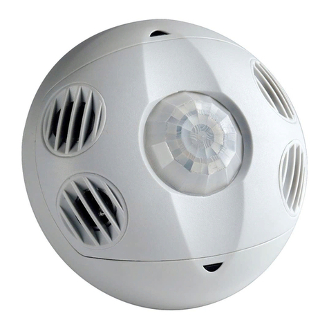
Wireless Occupancy Sensor with Photocell
Cat. No. ZC015
DI-000-ZC015-02A
Compatible Devices
• GreenMAX® DRC Wireless Keypad
• Zigbee 3.0 Room Controller
NOTES:
• Requires GreenMAX DRC Wireless Keypad or a Zigbee 3.0 Room Controller to
program and control communication to other devices.
• Mount the sensor after it has been programmed.
Quick Start: Enrollment and Verication
Enrollment
1. Remove "Battery Pull Tab" (on bottom) to activate device.
2. Place the sensor within 16 ft (5 m) from the desired receiver to program it.
3. Enroll sensor.
Press and hold button for 15 seconds until the LED indicator blinks White three (3)
times, then release immediately.
The device resets, and the LED indicator blinks Green approximately once per
second for 60 seconds to indicate the start of the join process.
3a.
To enroll sensor via QR code and mobile app:
• Use the camera on your mobile device to scan the QR code.
• Continue and save the sensor enrollment in the controller via the app.
•
After enrollment, use refresh option on app to show device successfully enrolled.
3b. To enroll sensor on a network:
Start Zigbee enrollment process for network controller.
4. To nd and bind enrolled sensor (step for non-Leviton controllers that need to
discover capability of sensor):
• Press and hold button for 10 seconds until the LED indicator blinks White twice,
then release immediately.
• The LED blinks Green approximately once per second as the sensor identies for
up to 180 seconds.
• Start Find and Bind: Initiates the controller to enroll the identied sensor.
Verication of Enrollment Process
Press and hold button up to 5 seconds, then release.
NOTES:
• If network enrollment is successful, LED indicator blinks Green once.
• If network enrollment is incomplete, LED indicator blinks Green twice.
• If there is no network connection, LED indicator blinks Blue once.
Installation
Do not mount sensor until it has been programmed to communicate with Room
Controller. Equipment needed for installation:
• Ceiling tile stem, nut, and washer (included)
• Double-sided foam mounting tape (included)
• Screws (included) and wall anchors (not included)
Operation Testing
1.
Once joined to the network, congure the sensor to control loads in required locations.
2. Conrm occupancy detection (Red LED blinks), then cover the occupancy sensor
to avoid further detection. Verify that the sensor times out and load turns OFF.
3. Uncover the occupancy sensor to verify Auto-ON responds and energizes loads.
Field-of-View and Sensitivity Testing
• Perform an FOV (Field-of-View) walk test of the coverage area and conrm the Red
LED blinks and detects occupancy within the coverage area.
• Use the app to adjust the sensor's sensitivity, as needed, to increase or decrease
the FOV.
Photocell Adjustment: Use the app to congure daylighting settings.
Button Action LED Color Blink Rate Sensor Status
No action. Green Rapid
Searching for network (up to 60 seconds);
Enrollment in process
Pressed and held
for fewer than
5 seconds.
Green
1 Time Enrolled in active Zigbee network.
2 Times Enrolled in active Zigbee network, but
not commissioned completely.
3 Times Enrolled in Zigbee network, but no
communication from network.
Blue 1 Time Not enrolled in Zigbee network.
No action. Blue 1 Time Power up on battery.
2 Times Power up on 24V DC source.
Pressed and held
for 5 to 9 seconds. White 1 Time Awake for 60 seconds before it reverts
to power save mode.
Pressed and held
for 10 to 14 seconds. White 2 Times
Leaves current network, if connected,
and triggers Find and Bind: Target for
enrollment for 180 seconds.
Pressed and held for
15 to 19 seconds. White 3 Times
Leaves current network, if connected
and performs Sensor Factory Reset.
Searches for network to enroll in up to
60 seconds.
Pressed and held
for more than
20 seconds.
N/A N/A N/A
No action. Red
1 Time Occupancy detected.
2 Times Battery replacement needed.
INSTALLATION INSTRUCTIONS ENGLISH
WARNINGS:
• TO AVOID FIRE, SHOCK, OR DEATH, TURN OFF POWER AT CIRCUIT
BREAKER OR FUSE, AND TEST THAT THE POWER IS OFF BEFORE WIRING!
• TO AVOID INJURY OR DEATH, DO NOT RECHARGE, DISASSEMBLE OR
INCINERATE BATTERY, OR HEAT IT ABOVE 212°F (100°C).
• Replace battery with an approved Lithium 3.6V non-rechargeable battery - Jauch
ER14505J-S, EVE ER14505V, or SAFT LS14500. Use of another battery may
present a risk of re or explosion.
CAUTIONS:
• Dispose of used battery promptly. DO NOT dispose of battery in normal household
waste. Please contact your local waste provider or recycling facility for proper
disposal of used battery.
• For indoor applications only.
• To be installed and/or used in accordance with electrical codes and regulations.
• If you are not sure about any part of these instructions, consult an electrician.
Product Description
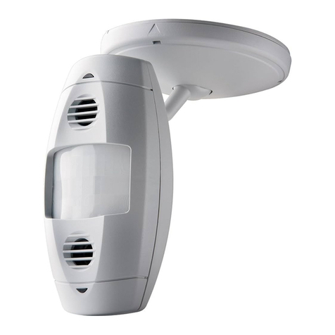
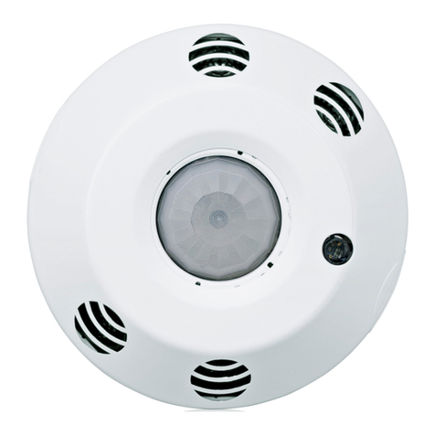
The occupancy sensor is a 2.4 GHz wireless communication device, which
transmits a wireless message to the Leviton room controller or wireless keypad.
This communication occurs each time there is a change to the occupation status or
change in light level. You can congure occupancy and vacancy time delays and
daylighting actions, which are maintained in the controller and load control devices.
The controller then routes the message to the load control device to take the
assigned action.
You can power this sensor by battery (observe proper polarity) or a +24V DC power
supply, such as OPP20. Refer to the image below.
Purpose of Control: Energy Management of Equipment
Pollution Degree: 2.
Connector for
24V DC Power Input
LED Indicator Operation
The occupancy sensor uses LED light colors to indicate occupancy status and
programming status, as shown in the table below.
Reset to Factory Default Settings
Press and hold button for 15 seconds until LED indicator blinks White three (3) times,
then release immediately.
NOTES:
• When reset is complete, LED blinks Green once per second, as sensor searches to
join the network.
• If you press the Green button for more than 20 seconds, the indicator times out, and
no functions are performed.
WEB VERSION
LIMITED 2 YEAR WARRANTY AND EXCLUSIONS
Leviton warrants to the original consumer purchaser and not for the benet of anyone else that this product at the time of its sale by Leviton is free of defects in materials and workmanship under normal and proper
use for two years from the purchase date. Leviton’s only obligation is to correct such defects by repair or replacement, at its option. For details visit www.leviton.com or call 1-800-824-3005. This warranty
excludes and there is disclaimed liability for labor for removal of this product or reinstallation. This warranty is void if this product is installed improperly or in an improper environment, overloaded, misused,
opened, abused, or altered in any manner, or is not used under normal operating conditions or not in accordance with any labels or instructions. There are no other or implied warranties of any kind, including
merchantability and tness for a particular purpose, but if any implied warranty is required by the applicable jurisdiction, the duration of any such implied warranty, including merchantability and tness for
a particular purpose, is limited to two years. Leviton is not liable for incidental, indirect, special, or consequential damages, including without limitation, damage to, or loss of use of, any equipment,
lost sales or prots or delay or failure to perform this warranty obligation. The remedies provided herein are the exclusive remedies under this warranty, whether based on contract, tort, or otherwise.
FOR CANADA ONLY
For warranty information and/or product returns, residents of Canada should contact Leviton in writing at Leviton Manufacturing of Canada ULC to the attention of the Quality Assurance Department,
165 Hymus Blvd, Pointe-Claire (Quebec), Canada H9R 1E9 or by telephone at 1-800-405-5320.
© 2023 Leviton Mfg. Co., Inc.
Minor Motion, Infrared
Major Motion, Infrared
0
0
20
10
10
20
SIDE VIEW
TOP VIEW
2011
11 1515 559920
8
0
Passive Infrared Field-of-View
For Technical Assistance Call: 1-800-824-3005 (USA Only) or 1-800-405-5320 (Canada Only) www.leviton.com
TRADEMARK DISCLAIMER
Use herein of third party trademarks, service marks, trade names, brand names and/or product names are for informational purposes only, are/may be the trademarks of their respective owners; such use is not meant to
imply affiliation, sponsorship, or endorsement.
Surface Mount Using Screws
1. Remove the back cover of the sensor: Locate the alignment arrow on the edge of
the back cover and on the edge of the front body, then rotate the back cover and
front body until the two arrows line up, and pull apart. Refer to Diagram B.
2. Use the included screws, nuts, and washers, or screws with commercially
available wall anchors to install the back cover. If necessary, drill pilot holes.
3. Secure the sensor's body to the back cover: Push back cover into front body and
rotate until the arrows do not align.
Surface Mount Using Tape
1. Remove backing material and apply double-sided mounting tape to the sensor base.
2. Press and hold the sensor to your desired mounting surface for a few seconds.
NOTE: The sensor's back cover and front body are keyed with arrows to lock and
separate it easily. To lock the sensor's body to the back cover, push back cover into
front body and rotate until the arrows do not align. To separate, rotate sensor until
the arrows are aligned, and pull apart.
Ceiling Tile Mount
1. Connect the included ceiling tile stem to the sensor's back cover and twist to
secure. Refer to Diagram A for details.
2. When sensor is in desired location, push the ceiling tile stem through the ceiling
tile and install the washer and nut above the ceiling tile to secure.
NOTE: The sensor's back cover and front body are keyed with arrows to lock and
separate it easily. To lock the sensor's body to the back cover, push back cover into
front body and rotate until the arrows do not align. To separate, rotate sensor until
the arrows are aligned, and pull apart.
Drop Ceiling
1 in. Thick Maximum
Nut Washer
Tile Stem
Diagram A
Sensor Mounted to Drop Ceiling with Tile Stem
Sensor location
optimized for best
entry detection
and reduced
nuisance tripping
from hallway.
Sensor location
center of room
has potential
risk of nuisance
tripping from
hallway traffic.
What to do if...
Load does not turn ON.
-Make sure the Red LED blinks every 15 seconds if there is occupancy. If not, separate the
device from other noisy electronics, such as personal computers, electronic ballasts,
and machinery.
- Use app to communicate to room controller and verify device is in the occupancy mode.
Press and hold device button for 5-9 seconds until LED blinks White once.
Select Device
Identify icon (magnifying glass) to have device LED ash Green repeatedly.
If unable to verify,
conrm that all devices on the network are within specied RF range.
-
Ensure that control devices are located properly to optimize RF design within installation location.
- Remove device and re-enroll it to the network.
- Reset sensor to its factory default settings.
- Check if sensor is actively daylighting (holding the lights OFF).
Location
Select the location to mount the sensor and the appropriate method:
- Tile stem
- Screws
- Mounting tape
NOTES:
• Sensor location is important to ensure correct operation within each unique space.
• Correct location improves Auto-ON response and reduces the risk of false tripping
from external motion (example, hallway traffic).
• Do not locate sensor on a mounting surface within 6 feet of air ducts, moving
machinery or heat sources.
• When used for daylighting, the sensor must be installed in the daylighting zone.
FCC STATEMENT
This equipment has been tested and found to comply with the limits for a Class B digital device, pursuant to part 15 of the FCC Rules. These limits are designed to provide reasonable protection against harmful interference in a
residential installation. This equipment generates, uses and can radiate radio frequency energy and, if not installed and used in accordance with the instructions, may cause harmful interference to radio communications. However,
there is no guarantee that interference will not occur in a particular installation. If this equipment does cause harmful interference to radio or television reception, which can be determined by turning the equipment off and on, the user
is encouraged to try to correct the interference by one or more of the following measures:
• Reorient or relocate the receiving antenna.
• Increase the separation between the equipment and receiver.
• Connect the equipment into an outlet on a circuit different from that to which the receiver is connected.
• Consult the dealer or an experienced radio/TV technician for help.
FCC SUPPLIER’S DECLARATION OF CONFORMITY
This device complies with part 15 of the FCC Rules. Operation is subject to the following two conditions:(1) This device may not cause harmful interference, and (2) this device must accept any interference received, including
interference that may cause undesired operation. Any changes or modications not expressly approved by Leviton Manufacturing Co., could void the user's authority to operate the equipment. Leviton Manufacturing Co., Inc.
201 North Service Road, Melville, NY 11747, www.leviton.com.
IC STATEMENT
This device complies with Industry Canada licence-exempt RSS standard(s). Operation is subject to the following two conditions: (1) this device may not cause interference, and (2) this device must accept any interference, including
interference that may cause undesired operation of the device.
RF EXPOSURE COMPLIANCE INFORMATION
To ensure compliance with FCC’s and ISED Canada’s RF exposure requirements this device must be installed to provide a minimum of 20 cm between the device and people.
Nut
Washer
Back
Cover
Mounting
Screw
Mounting
Screw
Sensor Base
Back Cover
Shown Mounted
to Ceiling with Screws
Back Cover (Inside)
Front Cover
Key Lock
Arrow
Wallboard
Ceiling
Mounting Option Diagram B
Sensor Mounted to Wallboard or Drop Ceiling Using Screws
WEB VERSION

Other Leviton Accessories manuals

Leviton OSFHU-CTW User manual

Leviton

Leviton OSFHU-CTW User manual

Leviton AEHTK User manual

Leviton

Leviton AEHTK User manual

Leviton decora smart DW15R User manual

Leviton

Leviton decora smart DW15R User manual

Leviton OSSMD-FT User manual

Leviton

Leviton OSSMD-FT User manual

Leviton OMNISTAT2 Mounting instructions

Leviton

Leviton OMNISTAT2 Mounting instructions

Leviton renu RER15 User manual

Leviton

Leviton renu RER15 User manual

Leviton ODD10-ID User manual

Leviton

Leviton ODD10-ID User manual

Leviton IPP0R User manual

Leviton

Leviton IPP0R User manual

Leviton Acenti AC315 User manual

Leviton

Leviton Acenti AC315 User manual

Leviton Lev-Lok M56AA User manual

Leviton

Leviton Lev-Lok M56AA User manual

Leviton OSWHB-I Series User manual

Leviton

Leviton OSWHB-I Series User manual

Leviton 5249 Service manual

Leviton

Leviton 5249 Service manual

Leviton OSC05-M0W User manual

Leviton

Leviton OSC05-M0W User manual

Leviton JCC ToughLED Pro User manual

Leviton

Leviton JCC ToughLED Pro User manual

Leviton ODS15-I1 User manual

Leviton

Leviton ODS15-I1 User manual

Leviton ODP10-I1W User manual

Leviton

Leviton ODP10-I1W User manual

Leviton WSCPC User manual

Leviton

Leviton WSCPC User manual

Leviton Renu RUAA1 Series User manual

Leviton

Leviton Renu RUAA1 Series User manual

Leviton ODS15-I1I User manual

Leviton

Leviton ODS15-I1I User manual

Leviton Lumina LURPC-OOW User manual

Leviton

Leviton Lumina LURPC-OOW User manual

Leviton OSF10 User manual

Leviton

Leviton OSF10 User manual

Leviton MDS10-ID Series User manual

Leviton

Leviton MDS10-ID Series User manual

Leviton 80301 User manual

Leviton

Leviton 80301 User manual

Leviton 279-S00 User manual

Leviton

Leviton 279-S00 User manual

Popular Accessories manuals by other brands

HoMedics ellia ASCEND quick start guide

HoMedics

HoMedics ellia ASCEND quick start guide

SICK Bluetooth WLA16 operating instructions

SICK

SICK Bluetooth WLA16 operating instructions

Dometic 9108853211 operating instructions

Dometic

Dometic 9108853211 operating instructions

DCU Tecnologic 34155011 instructions

DCU Tecnologic

DCU Tecnologic 34155011 instructions

dol sensors DOl 10 Technical user guide

dol sensors

dol sensors DOl 10 Technical user guide

Onix T624W100DA2b instruction manual

Onix

Onix T624W100DA2b instruction manual

Lascal BuggyBoard Maxi owner's manual

Lascal

Lascal BuggyBoard Maxi owner's manual

SICK UC40-112 Series operating instructions

SICK

SICK UC40-112 Series operating instructions

Holtek WAS-2271EN manual

Holtek

Holtek WAS-2271EN manual

EVE Window Guard Get started

EVE

EVE Window Guard Get started

KERN KFE-TM manual

KERN

KERN KFE-TM manual

e2 elektro BIM-BAM GNS-921/N manual

e2 elektro

e2 elektro BIM-BAM GNS-921/N manual

Keysight U8480 Series Programming guide

Keysight

Keysight U8480 Series Programming guide

Honeywell RPW201A Mounting instruction

Honeywell

Honeywell RPW201A Mounting instruction

Meari Bell 5S quick guide

Meari

Meari Bell 5S quick guide

LEGRAND 5 742 00 manual

LEGRAND

LEGRAND 5 742 00 manual

Crane AE8-SPCD-2 user manual

Crane

Crane AE8-SPCD-2 user manual

TRENDnet TEG-S24M1F supplementary guide

TRENDnet

TRENDnet TEG-S24M1F supplementary guide

manuals.online logo
manuals.online logoBrands
  • About & Mission
  • Contact us
  • Privacy Policy
  • Terms and Conditions

Copyright 2025 Manuals.Online. All Rights Reserved.