Wire
3/8" (1.6 cm)
Wire
3/8" (1.6 cm)
Grounding connection
to box (if box has a
grounding terminal)
Wire Connector
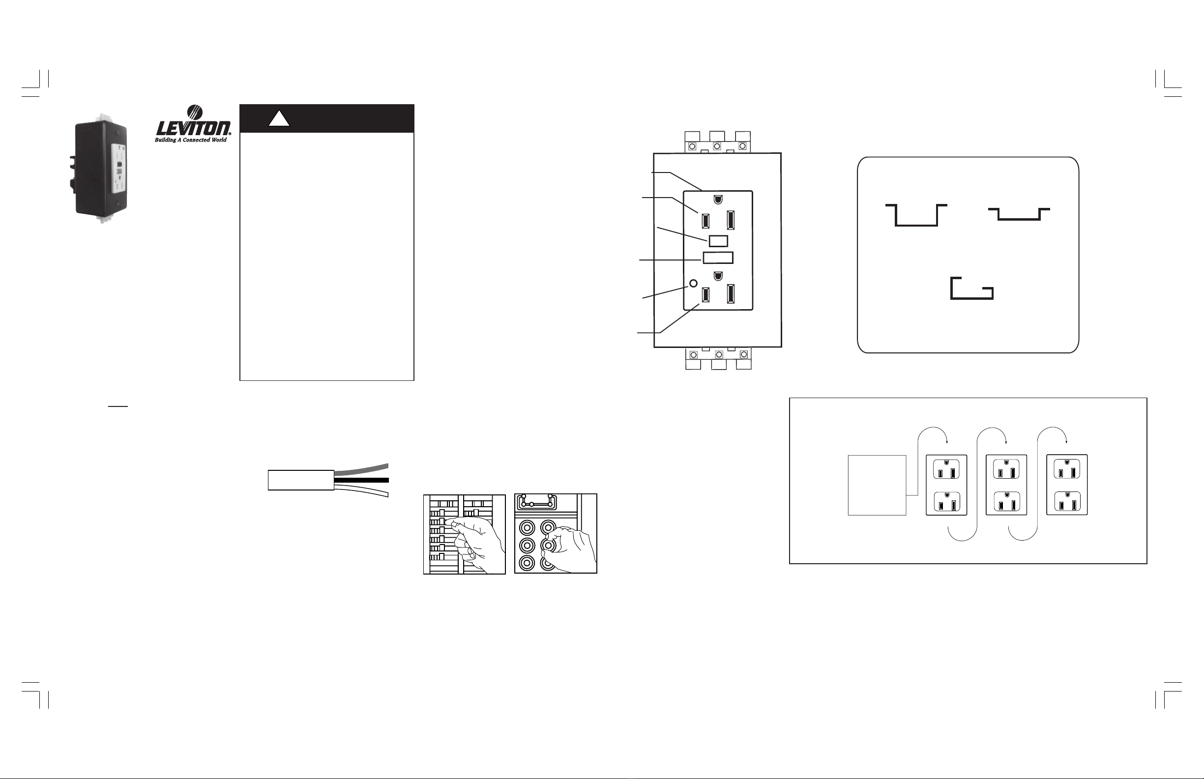
LINE cable brings
power to the GFCI
Electrical
Box
Electrical
Box
Wire
Connector
TROUBLESHOOTING
Turn the power OFF and check the wire connections against the appropriate wiring diagram
in step 8A or 8B. Make sure that there are no loose wires or loose connections. Start the test
from the beginning of step 9 if you rewired any connections to the 8598-DIN with GFCI.
General Information
GFCI rating:
15A-125V AC - Cat No. 8598 Lighted
Receptacle
This device is rated 20A feed-through.
For Technical Assistance Call:
1-800-648-3332 (U.S.A. Only); 1-800-405-5320 (Canada Only)
www.leviton.com
OR
About Wire Connections
To 8598-DIN:
Connect the LINE cable wires to the 8598-DIN LINE-INPUT terminals:
•The white wire connects to the Neutral (N) terminal.
•The black wire connects to the Line (L), or Hot, terminal.
Connect the LOAD cable wires to the 8598-DIN LOAD-OUTPUT terminals:
•The white wire connects to the Neutral (N) terminal.
•The black wire connects to the Line (L), or Hot, terminal.
Connect the grounding wires (only if there is a grounding wire):
•Connect a bare copper (or GREEN) 12 or 14 AWG wire to the grounding terminal on the
8598-DIN. If the box has a grounding terminal, also connect a similar wire to the grounding
terminal on the box. Connect the ends of these wires to the LINE or LOAD cable's bare copper
(or GREEN) wire using a wire connector. If these wires are already in place, check the
connections.
Complete the installation:
•Test your work. Go to step 9.
LOAD cable feeds
power to other
receptacle(s)
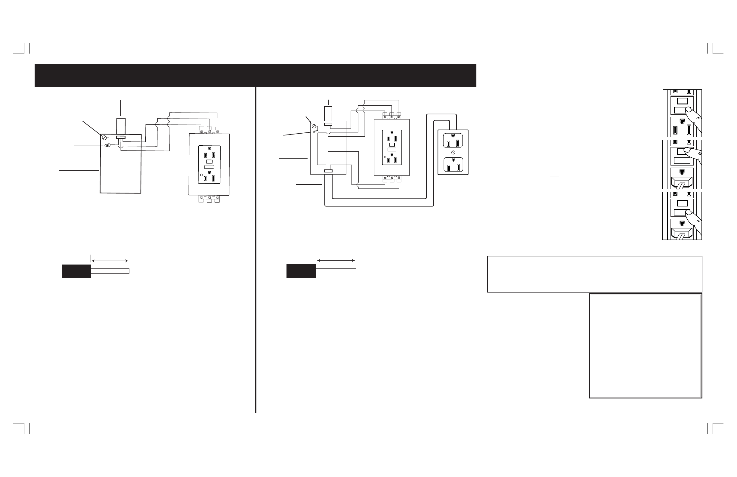
RESET
TEST
TEST
RESET
RESET
TEST
TEST
RESET
RESET
TEST
TEST
RESET
LINE cable brings
power to the GFCI
Grounding connection
to box (if box has a
grounding terminal)
8. Connect the wires (choose A or B)... only after reading other side completely:
A: Non-Feed-thru Installation OR B: Feed-thru Installation (provides downstream protection)
LIMITED 2 YEAR WARRANTY AND EXCLUSIONS
Leviton warrants to the original consumer purchaser and not for the
benefit of anyone else that this product at the time of its sale by Leviton
is free of defects in materials and workmanship under normal and proper
use for two years from the purchase date. Leviton’s only obligation is to
correct such defects by repair or replacement, at its option, if within
such two year period the product is returned prepaid, with proof of
purchase date, and a description of the problem to Leviton
Manufacturing Co., Inc., Att: Power Quality Customer Support, 860
Harold Place, Chula Vista, CA 91914 (In Canada send to Leviton
Mfg. of Canada Ltd., 165 Hymus Blvd., Pointe Claire, (Quebec),
Canada H9R 1E9). This warranty excludes and there is disclaimed
liability for labor for removal of this product or reinstallation.This warranty
is void if this product is installed improperly or in an improper
environment, overloaded, misused, opened, abused, or altered in any
manner, or is not used under normal operating conditions or not in
accordance with any labels or instructions.There are no other or implied
warranties of any kind, including merchantability and fitness for a
particular purpose, but if any implied warranty is required by the
applicable jurisdiction, the duration of any such implied warranty,
including merchantability and fitness for a particular purpose, is limited
to two years. Leviton is not liable for incidental, indirect, special, or
consequential damages, including without limitation, damage to, or loss
of use of, any equipment, lost sales or profits or delay or failure to perform
this warranty obligation. The remedies provided herein are the exclusive
remedies under this warranty, whether based on contract, tort or
otherwise.
DI-000-08598-00A
About Wire Connections
To 8598-DIN:
Connect the LINE cable wires to the 8598-DIN LINE-INPUT terminals:
•The white wire connects to the Neutral (N) terminal.
•The black wire connects to the Line (L), or Hot, terminal.
Connect the grounding wire (only if there is a grounding wire):
•For installations with no grounding terminal (diagram not shown): Connect the LINE
cable's bare copper (or GREEN) wire directly to the grounding terminal on the 8598-DIN.
•For installations with a grounding terminal (diagram shown above): Connect a bare copper
(or GREEN) 12 or 14 AWG wire to the grounding terminal on the 8598-DIN. Also connect a
similar wire to the grounding terminal on the box. Connect the ends of these wires to the
LINE cable's bare copper (or GREEN) wire using a wire connector. If these wires are
already in place, check the connections.
Complete the installation:
•Test your work. Go to step 9.
9. Test your work
Why perform this test?
•If you miswired the 8598-DIN, with GFCI, it may not prevent personal injury
or death due to a ground fault (electrical shock).
•If you mistakenly connect the LINE wires to the LOAD terminals, the
GFCIwill still operate like an ordinary receptacle, but it will not interrupt
a ground fault.
Procedure:
(a) This 8598-DIN is shipped from the factory with its GFCI in the tripped
condition and cannot be reset until it is wired correctly and power is
supplied to the device. Plug a lamp or radio into the GFCI (and leave it
plugged in). Turn the power ON at the service panel. Ensure that the GFCI
is still in the tripped condition by pressing the TEST button. If the lamp or
radio is ON and the Indicator Light is ON, go to the Troubleshooting
section because LINE and LOAD wiring connections have been reversed.
(b) Press the RESET button fully. If the lamp or radio turns ON and the
Indicator Light turns ON, the 8598-DIN has been installed correctly. If the
GFCI can not be reset, go to the Troubleshooting section.
(c) If you installed your 8598-DIN (with GFCI) using step 8B, press the TEST
button, then plug a lamp or radio into surrounding receptacles to see which
one(s), in addition to the GFCI, lost power when you pressed the TEST
button . DO NOT plug life saving devices into any of the receptacles that
lost power. Place a "GFCI Protected" sticker on every receptacle that lost
power, then press the RESET button to reset the GFCI.
(d) Press the TEST button (then RESET button) every month to assure
proper operation. If the GFCI can not be reset, then it must be replaced.
Can be used with
3880-DIN,16252-DIN, etc.
Black
White
RESET
RESET
TEST
TEST
TEST MONTHLY
TEST MENSUEL
FOLLOW DIRECTIONS
SUIVEZ INSTRUCTION
LN
G
Bare (or Green)
White
No Connection
LINE-INPUT
LOAD-OUTPUT
Black
White
White
RESET
RESET
TEST
TEST
TEST MONTHLY
TEST MENSUEL
FOLLOW DIRECTIONS
SUIVEZ INSTRUCTION
Bare (or Green)
White
Black
White
L
L
G
G
N
N
LINE-INPUT
LOAD-OUTPUT
DI-000-08598-00A 5/9/03, 2:31 PM2