Levitronix PuraLev 200SU User manual

User Manual for PuraLev®200SU
www.levitronix.com
PL-4030-00, Rev06, DCO# 20-144
First Release: 23-Oct-2013
Last Update: 09-Jul-2020
PuraLev®200SU
2 bar (29 psi)
21 liters/min (5.5 gallons/min)
USER MANUAL
This manual contains information necessary for the safe and proper use of the PuraLev®200SU. Included are
specifications for the standard configurations of the pump system and instructions regarding its use, installation,
operation, adjustment, inspection and maintenance. For special configurations of the pump system refer to
accompanying information. If the system must be configured for other parameter settings, then the Levitronix®Service
Software version V2.0.5.0 or higher (with according manual Levitronix
Doc.# PL-4046-00) is necessary. Familiarize
yourself with the contents of the manual to ensure the safe and effective use of this product. After reading this
manual, please store the manual where the personnel responsible for operating the pump system can readily refer to
it at any time.

User Manual for PuraLev®200SU
www.levitronix.com
PL-4030-00, Rev06, DCO# 20-144
2
Table of Contents
1SAFETY PRECAUTIONS...............................................................................................................................................................3
2SPECIFICATIONS..........................................................................................................................................................................4
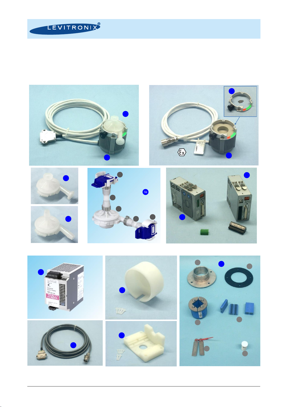
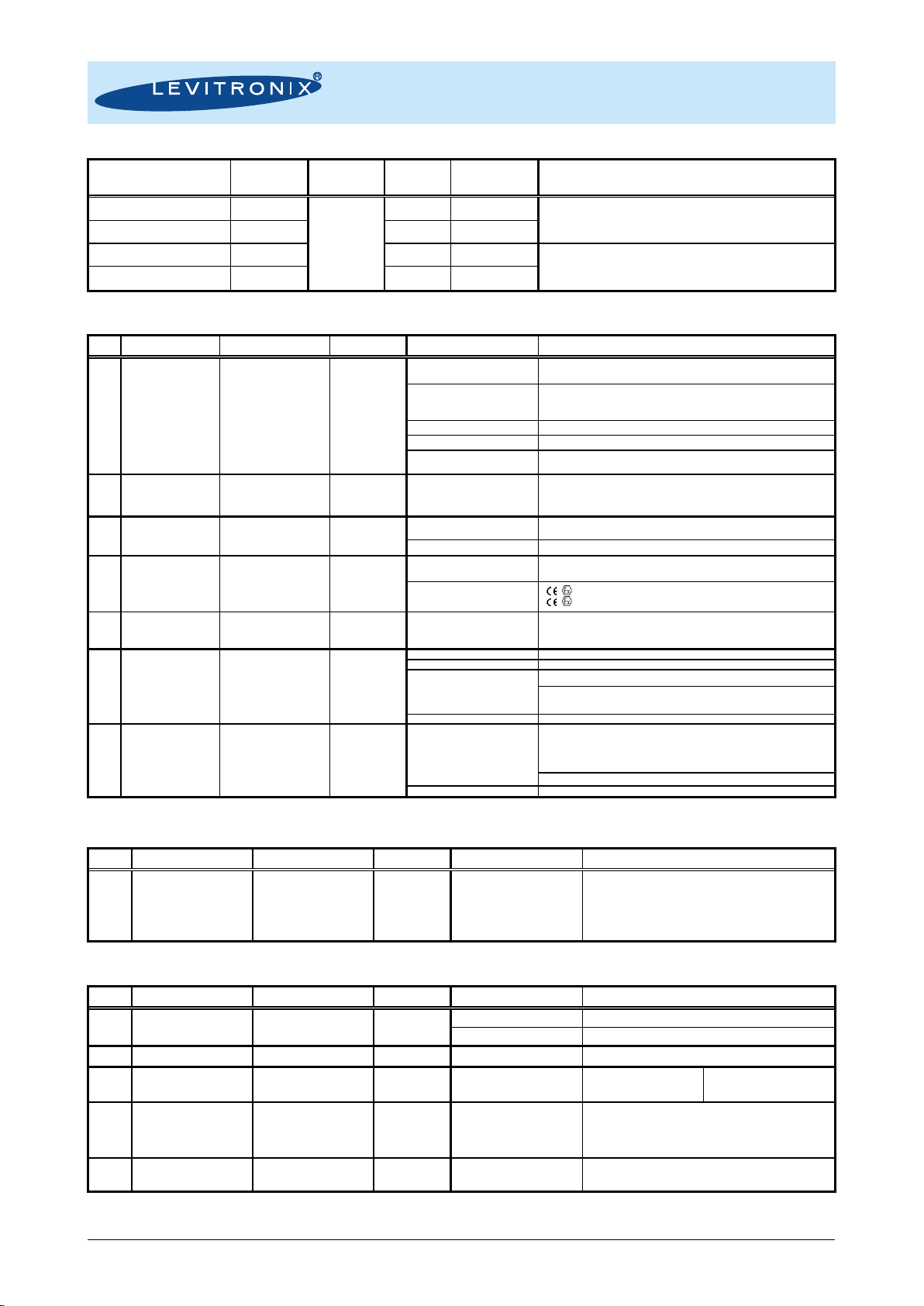
2.1 Specification of Components.................................................................................................................................................4
2.2 System Overview and General Specification.........................................................................................................................6
2.3 General Environmental Conditions........................................................................................................................................7
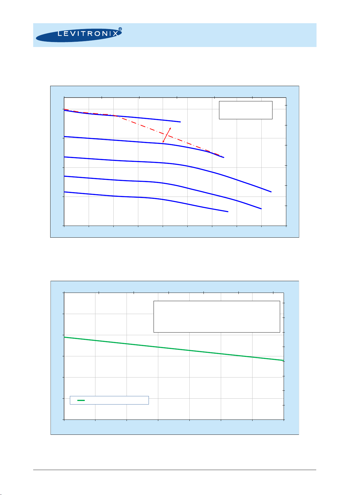
2.4 Pressure-Flow Curves...........................................................................................................................................................8
2.5 Maximum Static Pressure for Pump Heads...........................................................................................................................8
2.6 Basic Dimensions of Main Components................................................................................................................................9
3ENGINEERING INFORMATION...................................................................................................................................................12
3.1 Sealing and Material Concept .............................................................................................................................................12
3.2 Power Supply and Consumption.........................................................................................................................................13
3.3 Temperature Monitoring......................................................................................................................................................13
3.4 Thermal Management.........................................................................................................................................................14
3.1 Hydraulic Circuit Design......................................................................................................................................................17
4INSTALLATION ...........................................................................................................................................................................18
4.1 Electrical Installation of Controller .......................................................................................................................................18
4.2 Mechanical Installation of the Pump/Motor..........................................................................................................................24
4.3 Mechanical Installation of Motors in ATEX Zone 2 Areas ....................................................................................................24
4.4 Mechanical Installation of the Controller..............................................................................................................................24
4.5 Mechanical Installation of Adaptor/Extension Cables ..........................................................................................................25
5OPERATION................................................................................................................................................................................26
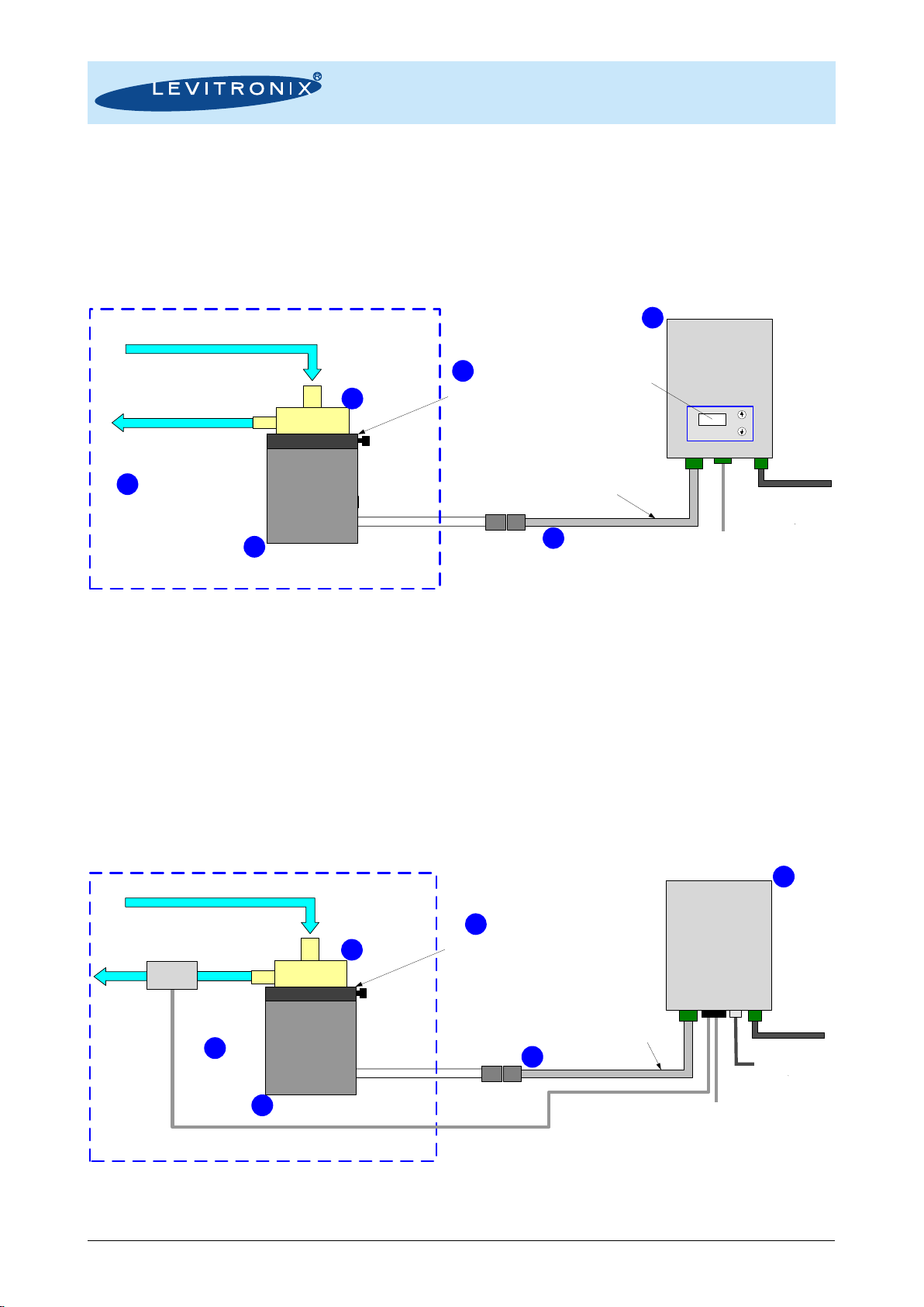
5.1 System Operation with LPC-200.1-01 (Stand-Alone Version)..............................................................................................26
5.2 System Operation with Controller LPC-200.2-01 (PLC version)...........................................................................................29
5.3 System Operation for ATEX / IECEx Applications ...............................................................................................................31
6INSTRUCTION FOR USE OF PUMP HEAD.................................................................................................................................32
6.1 Description and Preparation................................................................................................................................................32
6.2 General Warnings and Cautions .........................................................................................................................................32
6.3 Mounting of Pump Head......................................................................................................................................................33
6.4 Removal of Pump Head......................................................................................................................................................33
6.5 Assembly into Circuit...........................................................................................................................................................33
7TROUBLESHOOTING .................................................................................................................................................................34
7.1 Troubleshooting for Operation with Controller LPC-200.1-01...............................................................................................34
7.2 Troubleshooting for Operation with Controller LPC-200.2-01...............................................................................................34
7.3 Troubleshooting with Levitronix®Service Software..............................................................................................................34
8TECHNICAL SUPPORT...............................................................................................................................................................34
9APPENDIX...................................................................................................................................................................................35
9.1 Regulatory Status ...............................................................................................................................................................35
9.2 Symbols and Signal Words.................................................................................................................................................37

User Manual for PuraLev®200SU
www.levitronix.com
PL-4030-00, Rev06, DCO# 20-144
3
1 Safety Precautions
The PuraLev®200SU pump system is designed to be used in industrial production machines and equipment
containing hydraulic circuits. Typical applications are Single-Use Bioprocessing manufacturing equipment.
Installation shall be done by qualified personnel only. Following safety precautions and all “CAUTION”,
“WARNING” and “DANGER” indications in the relevant sections shall be followed.
CAUTION
Do not under any circumstances open the controller or motor. Levitronix®does
not assume responsibility for any damage, which occurs under such
circumstances.
CAUTION
High magnetic field strength of pump impeller.
The pump system contains a rotor magnet with high field strength. This may
alter or damage the calibration of sensitive electronic devices and measuring
instruments in the immediate surroundings. Keep at a safe distance from
computers, monitors and all magnetic data storage media (e.g. disks, credit
cards, audio and video tapes etc.)
!
WARNING
Hazardous voltage may be present.
In case of the usage of an inadequate AC/DC power supply, mains voltages
may be present (even if the system is designed for up to 24-48VDC). The
usage of a galvanic separated power supply, which is certified by a 3rd party
(UL or CE), is highly recommended.
The controller must be grounded and placed in a spill protected electrical
cabinet. Do not under any circumstances open the powered controller. The
usage of galvanic separated AC/DC supply is highly recommended.
!
WARNING
High magnetic field strength of pump impeller.
The pump system contains a rotor magnet with high field strength.
Pacemakers may be influenced and magnetic forces may lead to contusions.
Keep distance to pacemakers and handle impeller with care.
!
WARNING
TOXIC CHEMICALS may be present.
When using the system to pump chemicals, skin contact and toxic gases may
be hazardous to your health. Wear safety gloves and other appropriate safety
equipment.
!
WARNING
Motors for ATEX / IECEx applications: only specific types of motors BSM-1.x
are classified for the use in ATEX Zone 2 classified locations. Refer to the
corresponding section in the manual.

User Manual for PuraLev®200SU
www.levitronix.com
PL-4030-00, Rev06, DCO# 20-144
4
2 Specifications
2.1 Specification of Components
Figure 1 shows the main system components (motor, controller and pump head) and Figure 2 illustrates the
accessories for the pump system.
Figure 1: Pump system with standard components
Figure 2: Accessories
1
2a
2b
3
4a
4b
1a
A
A
F
C
B
D
B
E
9
6
B
7
5
C
C
1b
8

User Manual for PuraLev®200SU
www.levitronix.com
PL-4030-00, Rev06, DCO# 20-144
5
Driver System
Article #
Pump Head
Socket
Motor
Controller
Note
PLD-200SU.1
100-90647
PHS-200.1
BSM-1.4
LPC-200.1-01
Direct cabling between motor and controller
PLD-200SU.2
100-90648
BSM-1.4
LPC-200.2-01
PLD-200SU.4 (ATEX)
100-90650
BSM-1.6
LPC-200.1-01
Adaptor/Extension (0.5 - 10m) cables according to Table 3 have to
be ordered as separate article with specified length.
ATEX cable sealing system can be ordered according to Table 4.
PLD-200SU.5 (ATEX)
100-90651
BSM-1.6
LPC-200.2-01
Table 1: Standard system configurations
Pos.
Component
Article Name
Article #
Characteristics
Value / Feature
1a
1b
1c
1d
Single-Use (SU)
Pump Head
DCP-200.2 (Triclamp)
DCP-200.3 (Barb)
DCP-200.2-G25
DCP-200.3-G25
(Gamma irradiated
with Dosage ≥25kGy)
100-90734
100-90792
100-91078
100-91122
Wet parts material
Fittings (In- and Outlet)
PP = polypropylene (FDA, USP-VI, Animal/BSE/TSE free)
Triclamp
Max. Flow
Max. Diff.-Pressure
Max. Viscosity / Density
21 liters/min / 55 gallons/min
2 bar / 29 psi
< 20 cP
Wet Pump Volume/Surface
24 ml / 150 cm2
Max. Liquid Temp.
600C / 1400F
Sterilization Methods
Robust against Gamma radiation up to 40 kGy
Note: Testing has been done at minimum dosis of 43 kGy.
1e
SU Pump Head
with Sterile Fittings
DCP-200.3-SF1-G25
100-91233
Pump Type (A) / Tubing (C)
Sterile Fittings (B)
Fitting Compatibility
Applied Gamma Dosage
DCP-200.3 (Barb) / Silicone
AseptiQuik®G from CPC®with part # AQG17008 3
Various sizes and types including autoclavable versions available at CPC®
≥ 25 kGy
2a
Motor
BSM-1.4
100-10005
Housing
- ETFE (chemical resistant) coated Aluminum
- waterproofed (IP67)
Cable / Connectors
1x 5m cables with FEP jacket / 1x D-SUB (direct cable to controller)
2b
Motor
(ATEX / IECEx)
BSM-1.6
100-10063
Cable / Connectors
1x 2m cable with FEP jacket / 1x circular (M23, IP-67)
(needs extension adaptor cable for connection to controller)
ATEX / IECEx Marking
II 3G Ex nA IIC T5 Gc
II 3D Ex tc IIIC T100°C Dc
3
Pump Head
Socket
PHS-200.1
100-90695
Mounting Type
Materials
Assembly Screws
Bayonet with locking pin
Anodized aluminum with PA pin
4pcs M3x8mm Stainless Steel (INOX A4)
4a
Standalone
Controller
(User Panel)
LPC-200.1-01
100-30027
(Enable connector
included)
Voltage / Electrical Power
200 W / 24-48 VDC
Housing Protection
IP20
Interfaces for
Standalone Controller
Panel to set speed (automatic storage on internal EEPROM)
PLC with
1x analog 4 - 20 mA
0 - 24 V (optocoupler)
1x digital output 0 - 24 V (relais)
Standard Firmware
C3.25
4b
Extended
Controller
(PLC and USB)
LPC-200.2-01
100-30028
(PLC connector
included )
Interfaces for
Extended Controller
PLC with
- up to 4 digital inputs 0 - 24V (optocoupler)
- up to 4 digital outputs 0 - 24 V (relais)
- up to 2 analog inputs 4 - 20mA
- up to 2 analog inputs 0 10 V
- up to 2 analog outputs 0 5 V
USB interface (for service and system monitoring)
Standard Firmware
C3.48
Table 2: Specification of standard components
(Note 1: CPC®and AseptiQuik®is a registered mark of the Colder Product Company.)
Pos.
Component
Article Name
Article #
Characteristics
Value / Feature
5
Extension Adaptor
Cable for Power
MCA-1.5-05 (0.5m)
MCA-1.5-30 (3m)
MCA-1.5-50 (5m)
MCA-1.5-70 (7m)
MCA-1.5-100 (10m)
190-10225
190-10231
190-10199
190-10232
190-10233
Jacket Material
Connectors
PVC-jacket
Wallmountable circular Hummel to D-SUB
connector
Table 3: Specification of adaptor/extension cables
Pos.
Component
Article Name
Article #
Characteristics
Value / Feature
6
Air Cooling Module
ACM-1.1
190-10003
Material / Connection Port
Air Pressure / Consumption
~ 0.5bar (7.2 psi)
7
Mounting Base Plate
MBP-1.1
190-10004
Material
PVDF
8
(A-F)
ATEX Cable
Sealing System
ACS-A.1
100-90292
Sleeve (A) / Gasket (B)
Frame (C)
Cable Module (D)
Stainless Steel and EPDM
Roxylon (EPDM rubber)
Note:
Lubricant (E) and measurement
plates (F) are included.
9a
AC/DC Power
Supply
TSP 360-124
(Standard Traco)
100-40016
Voltage / Power Output
Voltage Input
Certification
Dimensions
24 VDC / 360 W
85 132 / 187 264 VAC, autoselect
UL, CSA, CB, Semi F47
125 x 125 x 80 mm
9b
AC/DC Power
Supply
TSP 360-148
100-40017
Voltage / Power Output
48 VDC / 360 W
Table 4: Specification of accessories

User Manual for PuraLev®200SU
www.levitronix.com
PL-4030-00, Rev06, DCO# 20-144
6
2.2 System Overview and General Specification
2.2.1 Stand-Alone System Configuration
The stand-alone pump system configuration (Figure 3), consists of a controller with an integrated user panel
to set the speed manually. The speed is automatically stored in the internal EEPROM of the controller. As an
option, the speed can also be set with an analogue signal.
Figure 3: Standard system configuration for standalone operation
(Speed setting with integrated user panel)
2.2.2 Extended System Configuration
The extended version of the pump system (Figure 4) consists of a controller with an extended PLC interface.
This allows setting the speed by an external signal and enables precise closed-loop flow or pressure control
in connection with either a flow or a pressure sensor. A USB interface allows communication with a PC in
connection with the Levitronix®Service Software. Hence parameterization, firmware updates and failure
analysis are possible.
Figure 4: Standard system configuration for extended operation
(Pressure or flow control with external sensor)
Chemical Resistance and IP67 Space
Motor
Disposable
Pump Head
Fluid In
Fluid Out
Motor Cable
Adaptor/Extension Power Supply
24-48 VDC
200 W
Controller
for
Standalone
Operation
Stand Alone
Operation
Speed Control
PLC Interface
Speed Setting
- 1x Digital Input (Enable)
- 1x Digital Output (Status)
- 1x Analog Input (Speed)
Bayonet Socket
with Locking Pin
Chemical Resistance and IP67 Space
Motor
Disposable
Pump Head
Fluid In
Fluid Out
Motor Cable
USB
- Service
- Firmware Update
- Configuration etc.
Flow- or
Pressure
Sensor
Adaptor/Extension Cable
Extended PLC Interface
Speed, Flow
or Pressure Setting
- 4 Digital Inputs
- 4 Digital Outputs
- 4 Analoge Inputs
- 2 Analoge Outputs
Power Supply
24-48 VDC / 200 W
Controller
for
Extended
Operation
Bayonet Socket
with Locking Pin
Motor option with direct
cabling to controller
Motor option with
direct cabling
to controller
1
5
4a
2b
2a
1
5
4b
2a
2b
3
3

User Manual for PuraLev®200SU
www.levitronix.com
PL-4030-00, Rev06, DCO# 20-144
7
2.2.3 ATEX / IECEx System Configuration
Together with the standard pump-head and controllers an ATEX / IECEx certified motor allows installation of
motor and pump head within an ATEX Zone 2 area (see Figure 5). The ATEX / IECEx motor (Pos. 2b in
Table 2) comes delivered with special connectors and according extension cables (see Table 3). One option
to lead the cables outside of the Ex area is an Ex certified cable sealing system as listed in Table 4.
Figure 5: System configuration for ATEX IECEx applications
2.3 General Environmental Conditions
Usage
Indoor 1
Altitude
Up to 2000 m
Operating ambient temperature
0 to 40 0C
Storage ambient temperature
(Extremes for Transportation)
-20 to 80 0C
-20 to 70 0Cfor single-use pump head
Operating humidity range (relative humidity)
15 –95%(non-condensing)
Storage humidity range (relative humidity)
(Extremes for Transportation)
15 –95%(non-condensing)
Normal storage conditions
Ambient temp.: 20 to 30 0C
Relative humidity: 50% (non-condensing)
DC supply fluctuations
10% of nominal voltage
Transient over-voltages typically present on
the mains supply
Surge immunity according to EN 61000-4-5
(tested together with certified AC/DC power supply)
Pollution degree
2
Table 5: Environmental conditions for pump system
Note 1: Contact Levitronix®technical department (see Section 8) for outdoor usage.
Disposable
Pump Head
Fluid In
Fluid Out
Motor Power Cable
Adaptor/Extension Cable Power Supply
24-48 VDC / 200 W
All
Controller
Types
ATEX conform cable sealing system
Cabinet Boundary for
ATEX Zone 2 Area
ATEX Zone 2 Classified Location
Chemical Resistance and IP-67 Space
ATEX Motor
Bayonet Socket
with Locking Pin
1
5
4
2b
8
3

User Manual for PuraLev®200SU
www.levitronix.com
PL-4030-00, Rev06, DCO# 20-144
8
2.4 Pressure-Flow Curves
Figure 6: Pressure/flow rate curves
(Measured with pump head DCP-200.2)
2.5 Maximum Static Pressure for Pump Heads
Figure 7: Specification for maximum static pressure of pump heads DCP-200
Note 1: Pressure limits only valid for pump head mounted on motor.
Note 2: The above chart applies also to the pump head DCP-200.3-SF1-G25 with sterile fittings.
0
5
10
15
20
25
30
0.0 1.0 2.0 3.0 4.0 5.0
0.0
0.5
1.0
1.5
2.0
0.0 2.5 5.0 7.5 10.0 12.5 15.0 17.5 20.0 22.5
[psi]
[gallons/min]
[bar]
[liters/min]
Specific gravity = 1 g/cm3
Viscosity = 0.7 cP
Liquid Temp.: 40C
8000 rpm
7000 rpm
6000 rpm
5000 rpm
9000 rpm
Supply Voltage: 48 VDC
Supply Voltage: 24 VDC
0
10
20
30
40
50
60
70
80
77 87 97 107 117 127 137
0
1
2
3
4
5
6
25 30 35 40 45 50 55 60
[psi]
[°F]
[bar]
Liquid Temperature in [°C]
Max. Static Pressure for DCP-200
Safety Factor = 1.3 (according to EN12162)
Limitation: Given by deformation. Burst pressure is significantly higher
Ambient Temp = 25 C
Note: Pressure limit only valid for pumphead mounted on motor. Values
only valid after Gamma radiation doses of < 40 kGy.

User Manual for PuraLev®200SU
www.levitronix.com
PL-4030-00, Rev06, DCO# 20-144
9
2.6 Basic Dimensions of Main Components
Figure 8: Basic dimensions (in mm and [inch]) of motor BSM-1.x with pump head DCP-200.2
(for other configurations refer to according drawings)
4pcs M3x8
Screws
Locking Pin
Clamp OD = 25mm for Mini-
Bore ID
Standard: ASME BPE 2009
Outlet
Inlet

User Manual for PuraLev®200SU
www.levitronix.com
PL-4030-00, Rev06, DCO# 20-144
10
Figure 9: Basic dimensions (in mm and [inch]) of motor BSM-1.x with pump head DCP-200.3
(For other configurations refer to according drawings.)
4pcs M3x8
Screws
Locking Pin
Inlet
Outlet

User Manual for PuraLev®200SU
www.levitronix.com
PL-4030-00, Rev06, DCO# 20-144
11
Cable
Jacket
Cable OD
Motor Sensor
Minimum Bending Radius
Permanent Installation
Minimum Bending Radius
Sometimes Moved
FEP
8.50 mm
7x Cable OD
15 x Cable OD
PVC
9.50 mm
5x Cable OD
11 x Cable OD
Table 6: Specifications for min. bending radius of motor and adaptor cables for BSM-1
Note: If not mentioned explicitly all the cables are not suited for constant dynamic bending and movement!
Figure 10: Basic dimensions (in mm) of controller LPC-200.2-01
(Same basic dimensions for LPC-200.1-01)
Alternative for
mounting DIN
rail clips

User Manual for PuraLev®200SU
www.levitronix.com
PL-4030-00, Rev06, DCO# 20-144
12
3 Engineering Information
3.1 Sealing and Material Concept
Figure 11: Sealing and material concept
(Motor BSM-1.x with pump head DCP-200.2)
System
Component
Item
Materials
No
Description
Pump Head
DCP-200.2
1
Pump housing (lid and bottom)
PP (polypropylene)
2
Impeller
PP (polypropylene)
3
Rotor magnet
Rare-earth material
4
Welding seam
Infrared welding
Pump Head
Socket
PHS-200.1
5
Pump head socket ring
Anodized Aluminum
6
4x M3x8mm screws for motor mounting
Stainless Steel (INOX A4)
7
Locking Pin
PA
Motor
BSM-1.4
BSM-1.6
8
Sealing O-ring for motor housing
FPM (= FKM)
9
Cable bushing
FPM, cable jacket is FEP
10
Motor housing
ETFE coating, waterproof (IP-67)
Coils and electromagnetic circuit potted
with an epoxy compound (UL94 V0).
Table 7: Materials used in the BSM-1.x motor and DCP-200.2 pump head
(For other configurations refer to according specifications and drawings)
3
2
1
4
6
5
8
9
10
7

User Manual for PuraLev®200SU
www.levitronix.com
PL-4030-00, Rev06, DCO# 20-144
13
3.2 Power Supply and Consumption
Figure 12 shows the typical power consumption of the system. If other AC/DC power supplies than the
standard specified ones are used, it is recommended to evaluate them under demanding operating situations
like fast braking from maximum speed and during power on and take-off of the impeller.
Figure 12: Electrical power consumption
(Controller LPC-200.x with pump head DCP-200.2 and motor BSM-1.x)
3.3 Temperature Monitoring
To avoid overheating of the system, the controller and motor temperatures are monitored. If the controller
temperature exceeds 70°C (158°F) or the motor temperature 90°C (194°F) for a duration of more than 10
minutes, the system goes into an error state and the pump stops. At 80°C (176 F) controller temperature or
100°C (212°F) motor temperature, the system stops immediately.
Start
Temperature
Monitoring
WARNING
YES
Temperature
> 70°C ?
Temperature
> 80°C ?
YES
YES
ERROR
Temperature
higher than 70°C
for more than 10
minutes?
NO
ERROR
YES
NO
NO
Start
Temperature
Monitoring
WARNING
YES
Temperature
> 90°C ?
Temperature
> 100°C ?
YES
YES
ERROR
Temperature
higher than 90°C
for more than 10
minutes?
NO
ERROR
YES
NO
NO
Figure 13: Controller temp. monitoring
Figure 14: Motor temperature monitoring
0.0 1.0 2.0 3.0 4.0 5.0
0
25
50
75
100
125
150
175
200
0.0 2.5 5.0 7.5 10.0 12.5 15.0 17.5 20.0 22.5
[gallons/min]
[Watts]
[liters/min]
Specific gravity = 1 g/cm
3
Viscosity = ~ 0.7 cP
Liquid Temp.: 40C
8000 rpm
7000 rpm
6000 rpm
5000 rpm
9000 rpm
---- 48 VDC Supply
24 VDC Supply

User Manual for PuraLev®200SU
www.levitronix.com
PL-4030-00, Rev06, DCO# 20-144
14
3.4 Thermal Management
3.4.1 Motor Temperature
The motor temperature depends on the ambient and liquid temperature, as well as on the hydraulic
operation point. Figure 15, Figure 16 and Figure 18 illustrate the temperature characteristics of the motor
depending on these parameters. For higher liquid temperatures and hydraulic operating points active cooling
is recommended for example with the air cooling module ACM-1.1 (see Figure 17).
Figure 15: Temperature curves for the BSM-1.x motor @ 25 0C liquid temperature
(Pump head DCP-200.2, temperature is measured inside of the motor, contact temperature of surface is below this temperature)
Figure 16: Temperature curves for the BSM-1.x motor @ 60 0C liquid temperature
(Pump head DCP-200.2, temperature is measured inside of the motor, contact temperature is below this temperature)
77
97
117
137
157
177
197
0.0 1.0 2.0 3.0 4.0 5.0
25
35
45
55
65
75
85
95
0.0 2.5 5.0 7.5 10.0 12.5 15.0 17.5 20.0 22.5
[F]
[gallons/min]
[0C]
[liters/min]
Ambient Temp = 25
0
C
Liquid Temp. = 25 0C
Specific gravity = 1 g/cm3
Viscosity = 0.7 cP
---- 48 VDC Supply
24 VDC Supply
8000 rpm 7000 rpm
6000 rpm
9000 rpm
Absolute Temperature Limit
Recommended
Operational Limit
77
97
117
137
157
177
197
0.0 1.0 2.0 3.0 4.0 5.0
25
35
45
55
65
75
85
95
0.0 2.5 5.0 7.5 10.0 12.5 15.0 17.5 20.0 22.5
[F]
[gallons/min]
[0C]
[liters/min]
Ambient Temp = 25
0
C
Liquid Temp. = 60 0C
Specific gravity = 1 g/cm3
Viscosity = 0.7 cP
---- 48 VDC Supply
24 VDC Supply
8000 rpm
7000 rpm
6000 rpm
9000 rpm
4000 rpm
5000 rpm
Absolute Temperature Limit
Recommended Operational Limit

User Manual for PuraLev®200SU
www.levitronix.com
PL-4030-00, Rev06, DCO# 20-144
15
Figure 17: Temperature curves of motor BSM-1.x with Air Cooling Module ACM-1.1
(Pump head DCP-200.2, temperature is measured inside of the motor, contact temperature is below this temperature)
Figure 18: Influence of liquid temperature on motor temperature
(Measurement at 7000 rpm 11 lpm but gradients are representative for other operational points)
The above curves are measurements of the motor temperature at certain liquid and ambient temperatures.
Equation (Eq. 1) shows how to calculate the motor temperature for other liquid and ambient temperatures
based on these curves.
77
97
117
137
157
177
197
0.0 1.0 2.0 3.0 4.0 5.0
25
35
45
55
65
75
85
95
0.0 2.5 5.0 7.5 10.0 12.5 15.0 17.5 20.0 22.5
[F]
[gallons/min]
[0C]
[liters/min]
Ambient Temp = 25
0
C
Liquid Temp. = 60 0C
Specific gravity = 1 g/cm3
Viscosity = 0.7 cP
Air cooling with ACM-1.1
0.5 bar, ~25 C air
---- 48 VDC Supply
24 VDC Supply
8000 rpm 7000 rpm
6000 rpm
9000 rpm
Absolute Temperature Limit
Recommended Operational Limit
y = 0.49x + 48.001
y = 0.28x + 27.792
77
97
117
137
157
177
197
77 87 97 107 117 127 137
25
35
45
55
65
75
85
95
25 30 35 40 45 50 55 60
[F]
[F]
[0C]
Liquid Temperature in [0C]
Ambient Temp = 25 0C
Specific gravity = 1 g/cm3
Viscosity = 0.7 cP
Absolute Temperature Limit
No Active Cooling:
Temperature Gradiant = 0.49
(Liquid vs. Motor Temperature)
No Active Cooling:
Temperature Gradiant = 0.28
(Liquid vs. Motor Temperature)

User Manual for PuraLev®200SU
www.levitronix.com
PL-4030-00, Rev06, DCO# 20-144
16
orliquid/motgradienteTemperaturtgetemperaturAmbientT
etemperaturLiquidTetemperaturMotorT
CTtgCTCTCTTTTT
LMA
LM
ALMLALMALM 17Figuresee
14Figuresee
==
==
−+−+== )25()25()25,25(),( 0000
(Eq. 1)
All above presented thermal data are typical values, which are partly based on measurements and partly on
interpolations with a simplified thermal model and are therefore only guideline values and are suitable for a
first layout of the basic thermal concept. It is recommended to check the thermal values with the motor
placed on the final location and under worst case performance conditions of the application.
In order to account for thermal variations (like ambient temperature, closed chemical cabinets or corners
without ventilations) and to not significantly reduce the MTBF of the motor it is recommended to keep about
20 0Csafety distance to the absolute thermal limit of the motor (90 0C) when designing the thermal concept
of the pump system.
3.4.2 Controller Temperature
Depending on the ambient temperature and the placement of the controller additional cooling may be
required (see Figure 19). To improve cooling of the controller, place the device into a moving air stream. If
the controller is mounted in a compact area or adjacent to additional heat sources (e.g. a 2nd controller)
ensure that there is sufficient ventilation.
Figure 19: Temperature curves of controller LPC-200 vs. flow and speed
(for pumping with pump head DCP-200.1/2 and motor BSM-1.x)
The above curves are measurements of the controller temperature at 250Cambient. Equation (Eq. 2) shows
how to calculate the controller temperature for other ambient temperatures based on this curve.
etemperaturAmbientT
etemperaturControllerT
CTCTTTT
A
C
AACAC
18Figuresee =
=
−+= )25()25()( 00
(Eq. 2)
77
97
117
137
157
0.0 1.0 2.0 3.0 4.0 5.0
25
35
45
55
65
75
0.0 2.5 5.0 7.5 10.0 12.5 15.0 17.5 20.0 22.5
[F]
[gallons/min]
[0C]
[liters/min]
Ambient temp. = 25 0C
Specific gravity = 1 g/cm3
Viscosity = 0.7 cP
Absolute Temperature Limit
8000 rpm
7000 rpm
6000 rpm
9000 rpm 8000 rpm
---- 48 VDC Supply
24 VDC Supply
9000 rpm

User Manual for PuraLev®200SU
www.levitronix.com
PL-4030-00, Rev06, DCO# 20-144
17
3.1 Hydraulic Circuit Design
Following general design rules help to operate the pump system optimally considering efficiency, optimum
priming behavior and low shear forces:
1. The general rule for minimum shear forces and optimum priming behavior is to minimize the
pressure drop in the inlet circuit and avoid negative pressure at the inlet of the pump head.
2. Minimize tubing length at the inlet of the pump head and maximize the ID (not smaller than than
the pump head inlet ID of 9.5 mm is recommended). This reduces the pressure drop and the
tendency of cavitation.
3. Avoid any restrictions, valves, elbows, bended tubing and sharp edges at the inlet circuit of the
pump head, which potentially cause cavitation resulting in higher shear forces and bubble
collection in the pump head with the danger of priming loss.
4. Place the pump at the lowest point of the hydraulic circuit. Optimum is as much as possible
below a tank or reservoir. This optimizes priming behavior and keeps the inlet pressure positive
for low shear forces.
5. Keep the liquid level in the reservoir tank or bag as high as possible, which increases the inlet
pressure of the pump head and minimized heat up of the liquid.
6. When horizontal mounting of the motor, the optimum outlet angle of the pump head is 45
degree hence allowing gas bubbles to leave the pump head and keep it primed.
7. To minimize heat up of the liquid the overall pressure drop in the hydraulic circuit shall be
reduced as much as possible.
8. It shall be avoided to pump longer times against a closed valve, which can cause heat-up of the
liquid and higher shear forces.
9. At flows < 1 l/min it is recommended to use a bypass loop to assure that sufficient flow runs
through the pump head to wash-out gas bubbles and avoid heat stagnation.
10. At higher liquid temperature rules mentioned above become more important due to higher
cavitation tendency of the liquid.
Contact the Levitronix®Technical Service department (see Section 8) for more detailed considerations and
support on the design of the hydraulic circuit.

User Manual for PuraLev®200SU
www.levitronix.com
PL-4030-00, Rev06, DCO# 20-144
18
4 Installation
4.1 Electrical Installation of Controller
4.1.1 Overview
The LPC-200 controllers have signal processor controlled power converters with switched inverters for the
drive and the bearing windings of the motor. The signal processor allows precise control of pump speed and
impeller position. Figure 20 shows the interfaces of the standalone controller LPC-200.1 with stand-alone
and minimal PLC functions. Figure 21 shows the interfaces of the LPC-200.2 controller with extended PLC
functions and USB interface for communication.
Figure 20: Overview of the controller LPC-200.1-01 for standalone operation
Interface (as labeled)
Description
1
“MOTOR”
- Position, field and temperature sensor signals from motor
- Drive and bearing currents of the motor
Torque spec. for tightening of connector screws: Min. = 0.4 Nm, Max. = 0.6 Nm
2
“USER INTERFACE”
1 Digital Input
- Galvanic isolation with optocoupler
- Lowest input voltage for high level detection: min. 5 V
Typical 24 V / 16 mA, maximal 30 V / 20 mA
- Highest input voltage for low level detection: max. 0.8 V
- Minimum input resistance: RIN = 2.2 k
1 Digital Output
- Galvanic isolation with relay
- Relay: 1A / 30VDC, 0.3A / 125 VAC
1 Analog Input
- Analog current input: 4 –20 mA
- 450 Ohm shunt input
3
“POWER INPUT”
DC power input -> 24V or 48V
4
“Power on” Green LED
LED is on if supply voltage of signal electronics is present.
5
“Power Output off”
Red LED
Red LED is off if the switched output stage of the controller is enabled. If the LED is on, the bearing and
drive coils of the motor carry no current.
6
“RESET” Button
Reset button of the controller stage. The button is sunk mounted and can be activated for example with a
small screw driver.
7
2-Digit Display “Speed”
Rotational speed display in 100rpm
8
“UP” Button
Button for speed increasing and enabling of levitation
9
“DOWN” Button
Button for speed decreasing and disabling of levitation
10
“Firmware” Label
Firmware version and revision number
Table 8: Description of interfaces of LPC-200.1-01 controller
1
2
3
4
6
7
8
9
5
10

User Manual for PuraLev®200SU
www.levitronix.com
PL-4030-00, Rev06, DCO# 20-144
19
Figure 21: Overview of the controller LPC-200.2-01 for extended operation
Interface (as labeled)
Description
1
“MOTOR”
- Position, field and temperature sensor signals from motor
- Drive and bearing currents of the motor
Torque spec. for tightening of connector screws: Min. = 0.4 Nm, Max. = 0.6 Nm
2
“USER INTERFACE”
2 Analog Input
- Analog current input: 4 –20 mA
- 450 Ohm shunt input
2 Analog Input
- Analog voltage input 0 –10 V
- Direct connection, no galvanic isolation
- 7.8 kinput resistance
2 Analog Output
- Analog voltage output: 0 –5 V 1
- Direct connection, no galvanic isolation
- Max. output current: 2mA
4 Digital Input
- Galvanic isolation with optocoupler
- Lowest input voltage for high level detection: min. 5 V
Typical 24 V / 16 mA, maximal 30 V / 20 mA
- Highest input voltage for low level detection: max. 0.8 V
- Minimum input resistance: RIN = 2.2 k
4 Digital Output
- Galvanic isolation with relay
- Relay: 1A / 30VDC, 0.3A / 125 VAC
3
“USB”
USB interface
4
“POWER INPUT”
DC power input -> 24V or 48V
5
“Power on” Green LED
LED is on if supply voltage of signal electronics is present.
6
“Power Output off” Red LED
LED is off if the switched output stage of the controller is enabled. If the LED is on, the
bearing and drive coils of the motor carry no current.
7
“RESET” Button
Reset button of the controller stage
Table 9: Description of interfaces of LPC-200.2-01 controller
(1: 10V is basically possible, contact Levitronix technical department for details)
1
2
3
4
6
7
5

User Manual for PuraLev®200SU
www.levitronix.com
PL-4030-00, Rev06, DCO# 20-144
20
4.1.2 General Installation Instructions
!
WARNING
Hazardous voltage may be present.
Always isolate the electrical power supply before making or changing
connections to the unit.
In case of the usage of an inadequate AC/DC power supply, mains voltages
may be present (even if the system is designed for 24 - 48VDC). The usage of
a galvanic separated power supply, which is certified by a 3rd party (UL or CE),
is highly recommended.
!
WARNING
Hazardous voltage may be present.
The controller housing must be properly grounded and placed in a spill
protected electrical cabinet. Use one of the DIN-rail screws on the back side of
the controller housing.
Do not use different and longer screws, which may result in short-circuit within
the controller.
1. The controller casing must be grounded. The screws of the DIN-rail brackets can be used for grounding
(see Figure 22).
2. Connect the motor connector to the controller.
3. Connect the controller type specific connectors: see Section 4.1.3 for standalone operation with the LPC-
200.1-01, Section 4.1.4 for extended operation with LPC-200.1-01 and Section 4.1.5 for extended
operation with LPC-200.2-01
4. Depending on the required hydraulic operational point (see Figure 6), the pump system requires 24V or 48
DC supply voltage at a maximum power of 200 W. At a lower performance power supplies with smaller
power or bigger supplies to supply several pump systems simultaneously may be used. Consult Figure 12
to get the power consumption depending on the flow. Contact Levitronix for consulting and support on the
power supply solution.
5. Connect the DC supply wires to the power input connector of the controller. Make sure that the polarity is
correct (see Figure 20 and Figure 21) and that AC/DC power supply is off.
6. To secure the connectors, tighten all retaining screws.
Figure 22: Grounding of LPC-200 controller
Table of contents
Popular Laboratory Equipment manuals by other brands

Tuttnauer
Tuttnauer 2340EA-D Operation and maintenance manual

Kodak
Kodak X-Omat 5000 RA PROCESSOR installation instructions

Revolutionary Science
Revolutionary Science incufridge professional series instruction manual

Thermo Scientific
Thermo Scientific BF51731 Installation and operational manual

SciCan
SciCan Statim 2000 Service manual

TSI Incorporated
TSI Incorporated 8026 Operation and service manual

MO BIO Laboratories
MO BIO Laboratories PowerWater DNA instruction manual

Bruker
Bruker NMR CryoFIT installation manual

GREINER
GREINER Bio-One Sapphire MaxiPette Operation manual

Analytik Jena
Analytik Jena Biometra TOne Setup instructions

CORNING
CORNING Stripettor 4998 instruction manual

CEM
CEM MARS 6 quick start guide