Lewmar 8000 User manual

8000 Gypsy/Drum Windlass
Installation Manual
Issue B

PART 1 - HYDRAULIC ANCHOR WINDLASS
INSTALLATION
VERTICAL HYDRAULIC MODELS
Windlass 1 Remove the anchor windlass from the packing case.
Installation Ensure that you have the necessary parts required to
complete your system.
There are three items to position, the windlass, chain
pipe (optional) and controls. Remember to allow space
below deck for the motor - gearbox and for the
connection of the hydraulic lines from the windlass to the
power unit.
2 Position the windlass deck unit on the deck or in the
anchor well (see drawings for cut out dimensions)
such that the centre - line of the chain on the gypsy
aligns with the bow roller in a horizontal plane, and that
the vertical line is within 10 degrees of the chain gypsy.
Ensure that the chain achieves maximum contact around
the chain gypsy (i.e. at least 120 and preferably 180
degrees contact).
3 Cut and drill clearance holes in the deck for the windlass
and chain pipe, to the size detailed on the installation
template.
4 Apply bedding compound onto the joint faces and mount
the windlass and chain pipe with the gypsy facing pawl
facing aft and the chain stripper facing forward.

Hydraulic 5 The Lewmar 8000 hydraulic windlass is designed
Installation to be used with Lewmar Commander power packs or
similar power packs that give the required flow and
pressure. Plan the routing of the hydraulic lines
(including case drain lines) and run them from the
hydraulic supply to the windlass motor (see hose type
recommendations).
6 Connect the hydraulic feed and return lines to the
hydraulic windlass motor, ensuring that the connections
are secure (see motor specifications).
7 Connect the case drain line (see case drain line
specifications).
8 Find a suitable position for electric safety deck
switch(es), remote control and / or toggle switch in view
of the windlass, anchor line and bow roller. Connect up
the switch wiring to the Commander system (see
Commander manual) or a suitable proprietary system
ensuring that the minimum supply is 3 amps. The
switches require a 12V or 24V DC system depending on
available supply.
9 Check correct operation of the windlass (eg up / down).
If the rotation is incorrect swap the A + B hoses at the
motor, or swap the switch wiring, or swap the Directional
Control Valve (DCV) caps.

ANCHOR WINDLASS HYDRAULIC
SPECIFICATIONS
CUSTOM 8000
VERTICAL HYDRAULIC MODELS
Hydraulic The hydraulic motor is a fully reversible, high efficiency
Motors motor gearbox.
Model Motor Flow Min / Max Pressure
(Ltr / min) Max (Bar)
8000 500 cc/Rev 30 - 70 115
(1667 psi)
Note: (a) 3.78 litres
≈ 1 US Gallon
4.54 litres ≈ 1 Imperial Gallon
(b) 14.5 psi = 1 Bar
Anchor Model Max Pull Max Line Working
Windlass Speed Load
Specifications
8000 3750 kg 6-15 m 726 kg
8267 lb (20-49 ft) / min 1600 lb
Model Line Speed @ Weight
Working load
8000 Dependant on 260 kg / 572 lb
Power Pack

Hose For reliable operation and safety reasons, it is essential
Types to use the correct bore size of hose. To reduce pressure
drops in hose runs greater than 5 - 7 m it is
recommended a larger hose size is used.
The recommended hose bore sizes with their flow
requirements are given below.
Model Motor Flow Min
(Ltr / min) Bore Size
8000 500 cc/Rev Up to 40 3/4"
Up to 70 1”
Note: (a) 3.78 litres
≈ 1 US Gallon
4.54 litres ≈ 1 Imperial Gallon
(b) It is important that the correct hose
specification is used as this affects the
efficiency of the hydraulic motor and the
performance of the windlass.

IMPORTANT
Drain To obtain optimum shaft life a case drain line must be
Line fitted.
Min drain line bore diameter: 6mm (1/4")
Safe working pressure: 18 Bar (250 psi)
All drain lines should if possible be connected to the
reservoir separately.
Hydraulic The Lewmar Anchor Windlass hydraulic motors accept
Fittings the following fittings:
Motor ports - 3/4" BSP Female
Case Drain - 1/4" BSP Female
Hydraulic The connection of the service lines should be plumbed in
Connections as follows: -
A Case Drain Line Must Be Fitted.

PART 2 - OPERATION, MAINTENANCE.
CUSTOM 8000
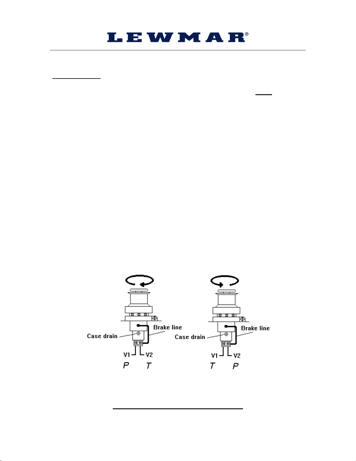
OPERATION OF VERTICAL HYDRAULIC MODELS
Operation The main shaft, driven by the motor / gearbox, is splined
Explained directly to the capstan. There is a fail-safe integral
brake fitted to the capstan. The brake is released when
hydraulic power is applied to the capstan. The gypsy can
either be powered by the capstan or free running. The
gypsy is powered by engaging the dog drive teeth of
the capstan to those of the gypsy. Engagement and
disengagement of the dog drive is controlled by turning
the top nut, which lifts and lowers the capstan. Spring
loading between the capstan and gypsy facilitates
engagement / disengagement.
The free running gypsy is controlled by tightening or
loosening the full wrap brake band.
Power Up Press the deck switch, remote control or toggle switch
(Anchor Up).
NOTE: Ensure that the brake band is released and that
the dog drive is fully engaged.
Power Down Press the deck switch, remote control or toggle switch
(Anchor Down).
NOTE: Ensure that the brake band is released and that
the dog drive is fully engaged.
Manual Chain Place a Lewmar winch handle in the brake band bi –
Release square and secure the chain gypsy. Place the Lewmar
winch handle into the top nut and raise the capstan until
the dog drive is fully disengaged.
Replace the handle in the brake band bi - square and
carefully release the brake to allow the gypsy to run free.
The descent of the chain can be controlled and stopped
by tightening the band.

Capstan Gypsy / Capstan model - To use the capstan (with rope
Operation only) lock the gypsy off with the brake band to stop the
chain from free running. Place a Lewmar winch
handle into the top nut and raise the capstan until the
dog drive is fully disengaged.
Press the Up button to power the Capstan.
Dog Drive Place a Lewmar winch handle into the top nut and lower
Engagement the capstan down onto the gypsy until resistance is felt,
then backwind one quarter of a turn.
Press the Up / Down switch and the dog drive will spring
down into positive engagement. Tighten down the top nut
securely if required.
Once the dog drive has been fully engaged, stop power
operation and release the brake band before powered
operation is continued.
Warning !
Ensure that the dog drive is fully engaged
when powering in or out.
Keep hands and feet clear of free running chain.
Do not leave a winch handle in the windlass while
operating.
Classification society rules require that a vessel lying at
anchor should have its chain held by a cable / chain
stopper or equivalent strong point as a windlass should
not be subjected to the loads generated under storm
conditions.
We recommend that the vessels engine should always be
used to aid anchor recovery.
Do not attempt to pull a load greater then the rated load of
the windlass.
When the windlass is not in use the anchor must be tied off
onto a cleat or equivalent strong point to prevent damage to
the vessel.

Maintenance The windlass is housed in the harshest environment on
the vessel. The windlass should be checked and cleaned
every six months. Wash away salt deposits using fresh
water, clean and grease the main shaft, spline and
bearings (using marine grade grease).
Remove the brake band assembly, clean brake band and
gypsy (Do not allow grease onto the brake band
surface). Check for wear and replace if necessary.
Check the motor / gearbox for signs of corrosion. If
corrosion is evident, clean and repaint with a marine
grade oil based enamel paint.

PART 3 - PARTS LIST, TECHNICAL DRAWINGS
SPARE PARTS LIST
8000 Part No Description Qty
Windlass 15001459 Support Pin 3
15001461 Friction Plate 1
15044121 Roller Bearing 6
65000405 Brake Band Cover Mk II 1
65000406 Centre Stem Mk II 1
65000407 Drive Shaft Mk II 1
65000411 Support Plate Mk II 1
65000412 Adjusting screw Mk II 1
65000413 Chain Stripper Mk II 1
65000423 Cleat Nut 8000 1
65000444 Top Bolt Mk II 1
65000449 Spacer Mk II 2
65000466 Pivot C / Bored Mk II 1
65000467 Pivot Threaded Mk II 1
65000480 Collet Ring Mk II 2
65000483 Bearing Retainer Mk II 1
65000545 Pillar Mk II 2
65000594 Washer 2
65000597 Sleeve 4
65000793 Hollow Dowel 4
65000798 Drum AW 1
65000858 Base 1
65000883 Spacer 1
68000243 Brake Band Assembly 1
B1798 Spring 4
B7789 Spiral Ext Clip 1
B8315 O ring 139.5 x 3.0 1
B8983 Rotary Seal 1
B9294 Brake Hose Assembly 1
B9397 Motor GearBox/Brake 1
B9467 Motor Valve Assembly 1
Gypsy Kits 60000004 16mm Shortlink
60000143 19mm Shortlink


LEWMAR LIMITED WARRANTY
Lewmar warrants its products in normal usage to be free of defects in materials and
workmanship for a period of three years from date of purchase by the original
purchaser, subject to the conditions, limitations and exceptions listed below. Any
part, which proves to be defective in normal usage during that three-year period, will
be repaired or at Lewmar’s option, replaced by Lewmar.
A CONDITIONS AND LIMITATIONS
i Lewmar’s liability shall be limited to repair or replacement of the
goods or parts defective in materials or workmanship.
ii Determination of the suitability of the material for the use
contemplated by the buyer is the sole responsibility of the buyer and
Lewmar shall have no responsibility in connection with such
suitability.
iii Lewmar shall not be liable in any way for:
a Failures, loss or damage due to use of products in applications
for which they are not intended.
b Failures, loss or damage due to corrosion, ultra violet
degradation, wear and tear or improper installation.
c Failures, loss or damage due to incorrect maintenance.
d Failures, loss or damage due to conditions that exceed the
product’s performance specifications.
iv Product subject to warranty claim must be returned to Lewmar for
examination unless otherwise agreed by Lewmar in writing.
v Lewmar shall not be responsible for shipping charges nor installation
labour associated with any warranty claim.
vi Service by anyone other than authorised Lewmar representatives
shall void this warranty unless it accords with Lewmar guidelines and
standards of workmanship.
vii Lewmar’s products are intended for use only for marine purposes.
Buyers intending to use them for any other purpose should seek
advice from Lewmar, and Lewmar shall be under no liability arising
from use, which Lewmar has not approved.
B EXCEPTIONS
Warranty is limited to a period of one year from the date of purchase in the
case of the following:
-Bowthrusters
- Electric motors and electrical equipment
- Electronic controls
- Hydraulic pumps, valves and actuators
- Weather seals
- Products used in “Grand Prix” racing applications

CLIABILITY
i Lewmar's liability under this warranty shall be to the exclusion of all
other warranties or liabilities (to the extent permitted by law). In
particular (but without limitation):
a Lewmar shall not be liable for:
- Any indirect or consequential loss including (without
limitation) any loss of anticipated profits, damage to
reputation or goodwill, loss of expected future business,
damages, costs or expenses payable to any third party or
any other indirect losses.
- Any damage to yachts or equipment.
- Death or personal Injury (unless caused by Lewmar's
negligence).
b Lewmar grants no warranties regarding the fitness for purpose,
use, nature or satisfactory quality of the goods.
ii Where the laws of the country do not permit a warranty to be
excluded, then such warranty, if permitted by that country's law, shall
be limited to a period of one year.

LEWMAR CONTACT DETAILS
LEWMAR SALES OFFICES
Lewmar UK/Rest of World
Lewmar Ltd, Southmoor Lane, Havant, Hampshire PO9 1JJ. UK
Tel (+44) 23 92 485700 Fax (+44) 23 92 485710
e-mail info@uk.lewmar.com
Lewmar USA
Lewmar Inc, New Whitfield Street, Guilford, CT 06437, USA
Tel (+1) 203 458 6200 Fax (+1) 203 453 5669
e-mail info@usa.lewmar.com
Lewmar Mid Europe
Lewmar Ltd, Branderweg 19, 8042 PD Zwolle, The Netherlands
Tel (+31) 38 427 34 90 Fax (+31) 38 421 56 42
e-mail [email protected]wmar.com
Lewmar Southern Europe
Lewmar Ltd, Place Bernard Moitessier, 17000 La Rochelle, France
Tel (+33) 5 46 50 50 46 Fax (+33) 5 46 50 59 04
e-mail [email protected]
Lewmar Southern Europe (Cannes)
Lewmar Ltd, Allée Charles Nungesser, Parc D’Activités de la Siagne 06210 Mandelieu,
France
Tel (+33) 4 93 48 80 48 Fax (+33) 4 93 48 37 50
e-mail [email protected]
Lewmar Southern Europe (Spain)
Lewmar Ltd, Sucursal en Espana, Joan de Borbó 92,
08039 Barcelona, Spain
Tel (+34) 93 221 94 37 Fax (+34) 93 225 19 49
e-mail info@spain.lewmar.com
Lewmar Northern Europe
Lewmar Marin AB, Argongatan 8, S-431 53, Mölndal, Sweden
Tel (+46) 31 277130 Fax (+46) 31 273116
e-mail info@sweden.lewmar.com
Lewmar Northern Europe (Finland)
Lewmar Marin AB (Finland), Laaksotie 10 A-B, 02700 Kauniainen, Finland
Tel (+358) 9 5489 5110 Fax (+358) 9 5489 5111
e-mail info@finland.lewmar.com
Table of contents
Other Lewmar Boating Equipment manuals
Popular Boating Equipment manuals by other brands

Lippert
Lippert SureShade 2000 Series installation manual

Dolphin
Dolphin Walk Around Boat T Top installation guide

CoverCraft
CoverCraft CARVER Bimini Top Installing

Pfeiffer
Pfeiffer LAZY JACK System I quick start guide

Classic Accessories
Classic Accessories DryGuard 20-089-092401-11 instructions

Taylor Made
Taylor Made Pontoon Quick-Shade Gazebo instructions

Wilderness Systems
Wilderness Systems AIRPRO 3D installation instructions

Glendinning
Glendinning HoseMaster user manual

SLEIPNER MOTOR AS
SLEIPNER MOTOR AS SIDE-POWER MIDI-202 installation manual

orangemarine
orangemarine W700 Series user manual

Vetus
Vetus DBPPJA installation manual

Samyung ENC
Samyung ENC SRG-3150DN manual