Lewmar Gen 2 S900 User manual

S2000
S900
Gen 2 S900/S2000 Stern Windlass
Product manual
Owners Installations, Operation & servicing manual
GB

MODEL ROPE
MOTOR
SUPPLY
MOTOR
POWER
WORKING
LOAD LIMIT
NORMAL
CURRENT
DRAW
CIRCUIT
BREAKER WEIGHT
mm in Voltage Watt kg lb Amp Amp kg lb
S900 12-16 ½” - ⅝” 12 600 200 440 85 90 11.6 26
S2000 12-16 ½” - ⅝” 12 1000 420 924 100 110 19.9 44
2
1- Introduction
Thank you for choosing Lewmar. Lewmar products are world renowned for their quality, technical innovation and
proven performance. With a Lewmar product you will be provided with many years of outstanding service.
Product support
Lewmar products are supported by a worldwide network of distributors and Authorised Service Representatives.
If you encounter any difficulties with this product, please contact your national distributor, or your local Lewmar
dealer. Details are available at: www.lewmar.com
CE Approvals
For CE approval certificates contact Lewmar.
Important information about this manual
Throughout this manual, you will see safety and product damage warnings.
You must follow these warnings carefully to avoid possible injury or damage.
2- Specification
2.1 Electric specifications
2.2 Gypsy specifications
Specifcally designed gypsy to suit leaded lines 12 to 16mm diameter.

136mm
54MM
144mm
71mm
190mm
262mm
40mm 140mm
22mm 20mm
45mm
90mm
34mm
54MM
72mm
68mm
139mm
331mm
136mm
140mm 22mm 20mm
45mm
90mm
50mm
34mm
GEN 2 S900/S2000 Stern Windlass ref B17416 iss.2 | 3
2.3 Dimensions
S900
S2000

4
WARNING!
3- Safety Notice
IMPORTANT: Read these notes before continuing.
3.1 Windlass general
At all times it is the responsibility of the boat user to ensure that the anchor and rode are properly stowed for
the prevailing sea conditions. This is particularly important with high-speed powerboats, because an anchor
accidentally deploying while under way can cause considerable damage. An anchor windlass is mounted in the
most exposed position on a vessel and is thus subject to severe atmospheric attack resulting in a possibility of
corrosion in excess of that experienced with most other items of deck equipment. As the windlass may only be
used infrequently, the risk of corrosion is further increased. It is essential that the windlass is regularly examined,
operated and given any necessary maintenance.
Please ensure that you thoroughly understand the operation and safety requirements of the windlass before com-
mencing the installation. Only persons who are completely familiar with the controls and those who have been
fully made aware of the correct use of the windlass should be allowed to use it. If there is any doubt of how to
install or operate this unit please seek advice from a suitably qualified engineer.
• Windlasses used incorrectly could cause harm to equipment or crew.
• Windlasses should be used with care and treated with respect.
• Boating, like many other activities can be hazardous. Even the correct selection, maintenance and use of proper
equipment cannot eliminate the potential for danger, serious injury or death.
• Lewmar windlasses are designed and supplied for anchor control in marine applications and are not to be used
in conjunction with any other use.
• Keep limbs, fingers, clothing and hair clear of windlass and anchor rope/chain and anchor during operation. Severe
bodily harm would result.
• Ensure there are no swimmers or divers nearby when dropping anchor.
• When the Windlass is not in use the anchor must be tied off onto a cleat or equivalent strong point to prevent
damage to the boat.
• Windlass must not be used as the sole means of securing the anchor to the bow fitting especially under storm
conditions. Anchors should be independently secured to prevent accidental release.
• Classification Societies require that a vessel lying at anchor must have its anchor rope/chain secured to a chain
stopper or other suitable independent strong point.
• A windlass should never be used as a mooring bollard, the anchor rode MUST be secured to a mooring cleat,
chain stopper or other designated strong point. Using the windlass to secure the rode will damage the
windlass.
• Do not use windlass for ANY purpose other than deployment and recovery of anchor.
• Do not wrap chain around a capstan barrel or drum where fitted.
• A circuit breaker/isolator should always be used with this windlass to protect the motor and cables from overheating
and damage.
• Always switch off this windlass at the circuit breaker/isolator when not in use.
• It is the unavoidable responsibility of the owner or master or other responsible party to assess the risk of any
operation on the vessel.
• Windlass must not be operated whilst under the influence of alcohol or drugs.
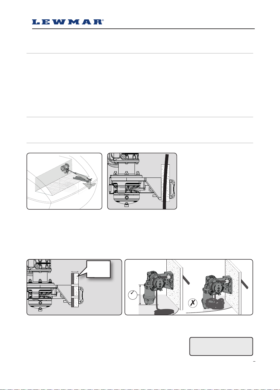
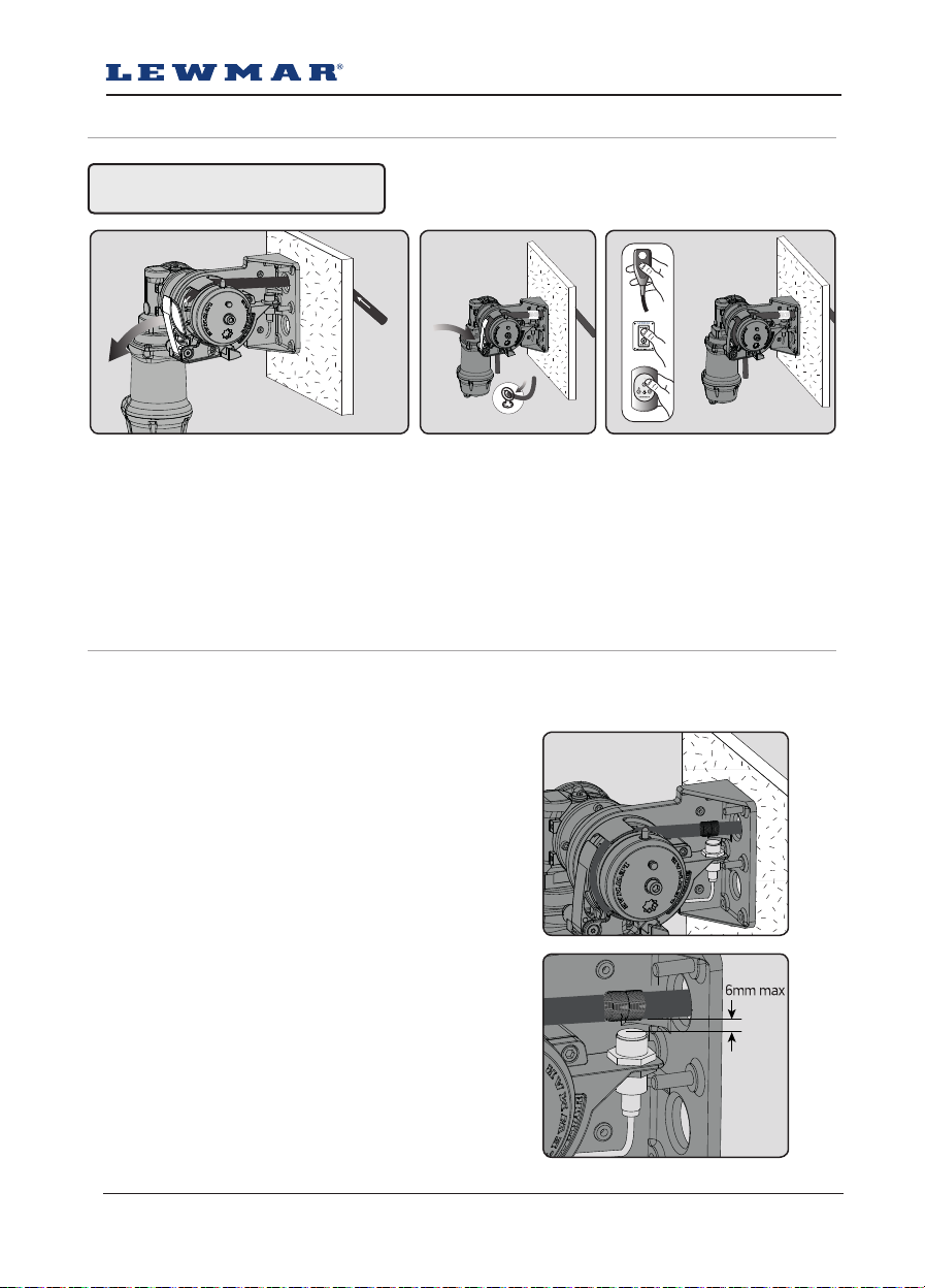
3.2 Fitting
• This equipment must be installed and operated in accordance with the instructions contained in this manual.
Failure to do so could result in poor product performance, personal injury and/or damage to your boat.
• Consult the boat manufacturer if you have any doubt about the strength or suitability of the mounting location.
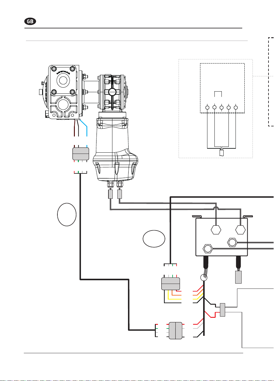
3.3 Electrical
• Make sure you have switched off the power before you start installing this product.
• This product requires installation by a suitably qualified electrical engineer.

3
300 mm
(12”)
25-30 mm
1” - 1 ³/₁₆”
4
2
1
GEN 2 S900/S2000 Stern Windlass ref B17416 iss.2 | 5
4- Installation
4.2 Accessories
Use only genuine Lewmar parts and accessories to ensure top performance and eliminate the risk of voiding your
warranty. For replacement parts, please visit your dealer or www.lewmar.com
4.3 Bulkhead preparation
IMPORTANT - Plan location carefully at the stern of the vessel and allow for the following:
1. Select an appropriate position taking into consideration the position of the anchor roller and the locker behind
the bulkhead . Lead from the roller should be fed in-line back to the the pulley and along its centre line.
2. If the bulkhead is not flat, a suitable mounting pad may be required to take up camber or sheer.
NOTE: If in doubt about the suitable construction of the pad consult a qualified marine engineer.
The bulkhead is an integral component of the windlass. It has to secure the windlass and be strong enough
to cope with the high torque stresses involved in recovering the anchor. Thin bulkhead made of foam or balsa
laminate construction, will require reinforcement in order to spread the loads applied while the windlass is in
use.
1. Lewmar recommends a minimum bulkhead thickness of 25mm (1”),
M8 Screws supplied suit bulkhead and packing thickness of 25-30mm (1” - 1 ³/₁₆” ).
Note: For thicker bulkheads, please source suitable length M8 countersunk screws.
2. Check clearance behind the bulkhead to fit the windlass including the motor
gearbox and allow for sufficient vertical fall (minimum of 300 mm /12” at all
times) for the lead line when hauling in.
WINDLASS INSTALLATION
• An appropriate marine sealant
• Electric drill and 9mm (⅜”) drill bit
• 50mm (2”) Hole Saw
• 5mm (³/₁₆”) Allen Key
• 13mm (½”) Spanner
WIRING INSTALLATION
• Crimping Pliers / Wire Stripper
• Suitable electrical cable and crimp terminals
4.1 Basic requirements
Each installation requires the following tools:
WARNING! Failure to
provide minimum vertical
fall will cause jamming.

2 3
1
6
1. Using the template and aer you have checked all the bulkhead requirements cut the following holes:
• Using a 9mm (⅜”) diameter drill bit, make the 4 holes to fit M8 mounting screws.
• With a 50mm (2”) diameter hole saw, make one hole for the rode to pass through.
• To help avoid water absorption by the deck, apply an appropriate marine sealant to the freshly cut hole edges.
• Assemble and tighten screws to 21Nm using a 5mm Allen key and 13mm spanner
• Secure the mounting plate in the chosen position using M10 screws and tighten to 43Nm using an 8mm allen
key and 17mm spanner.
4.4 Bulkhead fitting
3. Position 4 off gearbox mounting bolts, registering hex heads in recesses of housing, to give desired motor /
gearbox position.
• Insert 4 off M8 screws into prefered position and secure main unit. Tighten to 21Nm using a 6mm Allen key
4. Insert key into drivesha and slide motor / gearbox onto sha and secure to main unit using 4 off M8 nuts and
washers. Torque to 21Nm using a 13mm spanner.
NOTE: When fitting mounting bracket some adjustment may be required on the Bulkhead fixings.

2
1
1
ON
2
GEN 2 S900/S2000 Stern Windlass ref B17416 iss.2 | 7
To load the anchor rode:
1. Pass it through the bulkead roller unit
• Pull back the control arm
• Pass the rode around the gypsy and down through the bottom channel of the rope guide and into the locker
2. Gently release the control arm to keep the rode engaged in the gypsy.
• Secure end of rode to a suitable strong point.
3. The remainder of the rode can then be powered in.
1. Fit the sensor to the bracket
• Feed the sensor cable through the grommet on the
housing
• Secure so that it is clear of any moving parts and
falling anchor rode.
4.5 Loading the anchor rode
4.6 Fitting the auto-stop sensor and brass coil
WARNING! Isolate (turn off) the
windlass using circuit breaker / isolator.
The auto-stop function enables the windlass to stop automatically before the anchor reaches its final stowage
position. Allowing careful & controlled anchor stowage.
2. With the anchor lowered so it is just below water level,
adjust the height of the sensor so that it is within 6mm
of the anchor rode.
• Mark the rode above the sensor where the wire coil
(provided) will be fitted
3. Stow the anchor and cut power.
• Retrieve the rode where previously marked, ready to
attach the wire coil

3.1 3.2 3.3
3.4 3.5 3.6
4
5. Lower the anchor a few metres,then haul in. The Auto-stop
will activate, stopping the anchor as it breaks the water.
• The anchor can then be stowed by pulsing the windlass
while watching that the anchor is stowing correctly.
• Adjust the sensor height if required.
Note: During use the anchor rode may stretch, so the position
of the wire coil may also need adjusting.
8
4. Secure the wire coil to the anchor rode as shown in Fig 3.1 to 3.6
• Use an appropriate tool to pierce a hole through the rope.
• Push the brass wire through the rope and fold it lengthwise along the rope
• Wind the free end of the brass wire 8 times around the rope and over the other end of the wire.
• Knot and wind free ends together, trim down to approximately 5mm and secure under the wire wrap.
Note: The outer diameter of the wire wrap should be almost identical as the outer diameter of the rope so that the
sensor can detect the brass wire.
The brass wire may become worn by the sheave, especially under heavy load, it must therefore be checked regu-
larly and replaced if necessary.
Insure the motor direction is checked upon installation
to ensure the ‘up’ direction is correct and stops when
the sensor connection is made.

MODEL
MOTOR
SUPPLY
NORMAL CURRENT
DRAW
CIRCUIT
BREAKER 0 7 M 0 23 FT 7 15M 23 50FT 15 22M 50 73FT
Voltage Amp Amp MM² AWG MM² AWG MM² AWG
S900 12 85 90 16mm² 6 AWG 25mm² 4 AWG 35mm² 2 AWG
S2000 12 100 110 16mm² 6 AWG 25mm² 4 AWG 35mm² 2 AWG
GEN 2 S900/S2000 Stern Windlass ref B17416 iss.2 | 9
5- Electrical wiring
5.1 Electric cable selection
Lewmar recommends the installer source and install cable that meets the requirements of the standards and
regulations relevant to the installation and codes of practice.
The cable table gives recommended cable sizes based on total length of cable required, from the battery,
following the route of the cables.
5.2 Wiring
Plan the installation to suit the controls and give the operator a full view of the windlass. The wiring system
should be of the fully insulated type, which avoids possible electrolytic corrosion problems. We recommend the
use of type III stranded, tinned copper wire with copper crimp terminals. Most modern installations are negative
return (negative ground) but polarity should be checked.
Overload protection, in the form of the circuit breaker provided must be built into the windlass wiring circuit.
• Circuit breaker supplied:
S900 - 90A (Part No 68000349)
S2000 - 110A (Part No 68000350)
• The circuit breaker should be positioned close to the battery in a dry, readily accessible place.
• The breaker must be manually reset should an overload occur that causes it to trip to the off position.
• If you are not sure you understand these guidelines, seek professional help. Ensure that the installation
complies with USCG, ABYC, NMMA or other local regulations.
WARNING!
5.3 Control switch installation
The unit is supplied with
• Guarded rocker switch (product ref 68000593)
• Contactor Assy
- S900 - 68001213
- S2000 - 68001214
• Follow wiring diagram 5.4
NOTE: Optional electric footswitches and remote handheld control available.
Visit www.lewmar.com for more information
Optional wireless remote also available
See table below for models and references
Windlass performance is directly related to cable size and length.
Voltage drop over the complete wiring run must not exceed 10%.
NOTE: In a multi station installation all switches must be wired in a parallel circuit.
DO NOT confuse cable length
with the length of the vessel
WIRELESS REMOTE
3 BUTTON WINDLASS ONLY
WIRELESS REMOTE
5 BUTTON WINDLASS & THRUSTER
68000967 68000968

BROWN
BLACK
BLUE
RED
GREEN
WHITE
BLACK
RED
GREEN
WHITE
BLACK
B2
ON
+
+
RED
ORANGE
YELLOW
Proxi
Switch
cables
Switch
cable
F1 F2
-
213
GREEN
G/Y
1
3
2
2
1
A1
A2
5B3
B2
4
C1
3
ADD
LINK
WHITE
-
1 2 3 4
4 3 2 1
A1 B3 A2
Black
Red
UP
DOWN
BLACK
RED
BLACK
1
2
3
4Black
Red
White
RED
GREEN
WHITE
BLACK
GREEN
WHITE
RED
823
1234 1234
RED
GREEN
WHITE
BLACK
1234
RED
GREEN
WHITE
BLACK
RED
GREEN
WHITE
BLACK
A1
A2
10
5.4 S900 Wiring diagram
Installation instructions are supplied separately with any accessories.
Relay
Wireless Remote

BROWN
BLACK
BLUE
RED
GREEN
WHITE
BLACK
RED
GREEN
WHITE
BLACK
B2
ON
+
+
RED
ORANGE
YELLOW
Proxi
Switch
cables
Switch
cable
F1 F2
-
213
GREEN
G/Y
1
3
2
2
1
A1
A2
5B3
B2
4
C1
3
ADD
LINK
WHITE
-
1 2 3 4
4 3 2 1
A1 B3 A2
Black
Red
UP
DOWN
BLACK
RED
BLACK
1
2
3
4Black
Red
White
RED
GREEN
WHITE
BLACK
GREEN
WHITE
RED
823
1234 1234
RED
GREEN
WHITE
BLACK
1234
RED
GREEN
WHITE
BLACK
RED
GREEN
WHITE
BLACK
GEN 2 S900/S2000 Stern Windlass ref B17416 iss.2 | 11
Optional accessories
Rocker Switch
(68000593)
UP DOWN
Circuit Breaker
Battery
12 V DC
Fuse 3 A
Remote Handheld Control
(See www.lewmar.com)
(68001357)
Optional Wireless
Control Available
(See § 5.3)
Relay
Wireless Remote
Y Splitter
(68001289)

BROWN
BLACK
BLUE
RED
GREEN
WHITE
BLACK
RED
GREEN
WHITE
BLACK
B2
ON
+
+
RED
ORANGE
YELLOW
Proxi
Switch
cables
Switch
cable
F1 F2
-
213
GREEN
G/Y
1
3
2
2
1
A1
A2
5B3
B2
4
C1
3
ADD
LINK
WHITE
1 2 3 4
4 3 2 1
A1 B3 A2
1234 1234
Black
Red
UP
DOWN
BLACK
RED
BLACK
1
2
3
4Black
Red
White
RED
GREEN
WHITE
BLACK
RED
GREEN
WHITE
BLACK
GREEN
WHITE
RED
823
1234
RED
GREEN
WHITE
BLACK
RED
GREEN
WHITE
BLACK
A2 - NEG
F1 - F1
F2 - F2
12
5.5 S2000 Wiring diagram
Installation instructions are supplied separately with any accessories.
Relay
Wireless Remote

BROWN
BLACK
BLUE
RED
GREEN
WHITE
BLACK
RED
GREEN
WHITE
BLACK
B2
ON
+
+
RED
ORANGE
YELLOW
Proxi
Switch
cables
Switch
cable
F1 F2
-
213
GREEN
G/Y
1
3
2
2
1
A1
A2
5B3
B2
4
C1
3
ADD
LINK
WHITE
1 2 3 4
4 3 2 1
A1 B3 A2
1234 1234
Black
Red
UP
DOWN
BLACK
RED
BLACK
1
2
3
4Black
Red
White
RED
GREEN
WHITE
BLACK
RED
GREEN
WHITE
BLACK
GREEN
WHITE
RED
823
1234
RED
GREEN
WHITE
BLACK
RED
GREEN
WHITE
BLACK
GEN 2 S900/S2000 Stern Windlass ref B17416 iss.2 | 13
Rocker Switch
(68000593)
UP DOWN
Circuit Breaker
Battery
12 V DC
Fuse 3 A
Remote Handheld Control
(See www.lewmar.com)
68001357
Optional accessories
Optional Wireless
Control Available
(See § 5.3)
Wireless Remote
Y Splitter
(68001289)

ON
2 Sec
ON
1 2 3
1 2 4
14
6- Operation
WARNING! Trapping, crushing or
entanglement danger whiIst operating
windlass manually or under power
1. Disengage the windlass drive by pressing the
plunger button on the windlass drive cap until the
plunger remains in the down position.
• Release the anchor line
2. When safe insert the Lewmar wrench in to the
capstan drive cap. Rotate clockwise to grip the gypsy
and anticlockwise to free the gypsy controlling
the rate of descent of the anchor. Once deployed,
lock the clutch by turning the drive cap clockwise
and engage the anchor locks. Remove the wrench
handle.
3. To return the windlass back to powered operation
pull the locking button out disengaging the plunger.
Engage the circuit breaker/isolator and press the
UP/DOWN button.
6.1 Manual controlled freefall
Use this method for quicker anchor deployment, in an emergency involving loss of power or to save battery power.
Observe maritime anchor deployment safety rules.
WARNING! Isolate (Turn off) the
windlass using circuit breaker / isolator.
WARNING! Always remove
wrench handle after use
6.2 Power up/down
To release anchor:
1.Check unit is not in manual mode and the
plunger is disengaged/up position.
2.Release the anchor line
• Engage the circuit breaker/isolator.
• Press DOWN button for 2 seconds until the anchor
is under freefall. If the clutch was left in a locked
position the anchor will move almost immediately,
if unlocked it could take several seconds to fully
re-engage the internal clutch.
• NOTE: Pressing the DOWN button for over 5
seconds will result in a longer clutch re-engagement
time during the next UP command.
• Once enough line has been released press the UP
button continuously until freefall stops. It normally
takes several seconds to fully re-engage the
internal clutch mechanism, locking the windlass.
• NOTE: Failure to lock the windlass clutch could
result in rope creeping out.
3.To retrieve anchor: Press the UP button
continuously to retrieve the anchor.

13
2
GEN 2 S900/S2000 Stern Windlass ref B17416 iss.2 | 15
7- Servicing
7.1 Servicing schedule
The service period is determined by the frequency of use. Professional user will need to carry out these operations
more oen than the weekend user. Before commencing any work on this or any other electrical product, isolate
from the power source.
Bedding in period:
When new there are some areas that will need frequent checking. If no movement is found they can be inspected
less oen.
• Examine all electrical connections, to make sure they are sound and corrosion hasn’t set in.
Tighten if necessary and protect if required.
• Check mounting scews are firmly clamped and tighten if required.
Aer use:
• Wash down the windlass using fresh water.
• Ensure rode is at least 12” (300mm) below the windlass
• Check anchor locker drain
• Check rode for wear.
Annually or more oen if frequent user:
• Examine all electrical connections, to make sure they are sound and corrosion hasn’t set in.
Tighten if necessary and protect if required.
• Check mounting screws are firmly clamped and tighten if required.
• Check rode for wear.
• Check gypsy as it is a high wear item (For service and replacement see §7.2)
WARNING! Isolate the windlass
using circuit breaker/isolator
WARNING! Ensure rode is adequately
secured to an independent strong point
7.2 Gypsy replacement/service
1. Remove screw and washer from drive cap. Screw may require warming as it is sealed with Loctite®
2. Depress plunger so that it is held inside drive cap and unscrew Free-fall mechanism.
(LH thread when using stbd windlass)
3. Remove stripper retaining screws
• Pull control arm away from the gypsy.
• Move stripper to clear housing and remove the gypsy, take care to note direction of rope teeth for reassembly.
• Check parts for wear and replace as appropriate
• Clean thoroughly without solvent or wire brush and dry.
• Clean and lubricate Free - fall plunger.
• Re-Assemble, use a small amount of grease on the mating faces.
• Use loctite® on the assembly screws, making sure no Loctite residue gets on the thread of the driveshaft as it
will prevent the free fall function operating. The screws (Fig 3), Retaining the stripper should be tightened, then
backed off ½ turn to allow the stripper to lay loose on the gypsy.

1
36
8
11
13
17
18
19
20
21
22
23
24
25
26
27
28
29
31
32
33
34
35
7
36
37
16
10
38
42
15
5
43
9
4
12
41
39
40
44
16
7.3 Parts list

SPARES KIT
KIT NO DESCRIPTION ITEMS INCLUDED QTY
66000842 GEN 2 PORT CONTROL ARM KIT 7(1), 17(1), 18(1), 19(1), 21(1)
66000843 GEN 2 STBD CONTROL ARM KIT 36(1) , 17(1), 18(1), 19(1), 21(1)
66000099 CLUTCH LEVER 20(1)
66000833 GEN 2 PORT DRIVE CAP 16(1)
66000832 GEN 2 STBD DRIVE CAP 37(1)
66000834 GEN 2 BULKHEAD UNIT 22(1), 44(4)
66000835 GEN 2 MOUNTING BRACKET KIT 8(1), 32(2), 35(4)
66000844 GEN 2 PORT STOPPER CAM/ ROPE GUIDE KIT 6(1), 10(1), 33(1), 35(4)
66000845 GEN 2 STBD STOPPER CAM/ ROPE GUIDE KIT 38(1), 6(1), 33(1), 35(4)
66000810 GYPSY 23(1)
66000811 STRIPPER KIT 11(1), 28(2)
66000836 GEN 2 PORT DRIVE CONE KIT 3(1), 12(1), 27(1), 39(1)
66000837 GEN 2 STBD DRIVE CONE KIT 40(1), 41(1), 3(1), 27(1)
66000839 S900 PORT DRIVESHAFT KIT 1(1), 5(1), 13(1), 15(1)
66000838 S900 STBD DRIVESHAFT KIT 42(1), 1(1), 5(1), 13(1)
66000841 S2000 PORT DRIVESHAFT KIT 1(1), 4(1), 43(1), 13(1)
66000840 S2000 STBD DRIVESHAFT KIT 4(1), 9(1), 1(1), 13(1)
66001190 AUTOSTOP 24(1)
66000816 S900 MOTOR/ GEARBOX 25(1), 35(4), 29(4), 31(4), 34(4)
66000817 S2000 MOTOR/GEARBOX 26(1), 35(4), 29(4), 31(4), 34(4)w
GEN 2 S900/S2000 Stern Windlass ref B17416 iss.2 | 17
1. Anchor rode pays out independently while windlass is not in use.
• This problem is a result of not securing the rope combined with the gypsy drive cap being slack. Tighten the
gypsy drive cap using the winch handle and always secure the rope independently of the windlass when not in
use.
2. Failure to operate or sluggish operation.
• The majority of these problems are electrical in nature. It is essential that the proper voltage be maintained.
The proper voltage on a 12 Volt system is 13.5 Volts, constant low voltage will damage motor.
• Ensure electrical cable size is large enough to handle the current draw and keep voltage drop within acceptable
limits.
• Check control switches, connections, battery condition, isolator switch, fuse and motor for operation failure.
3. Failure to operate.
• Is there a voltage at the input terminals to the contactor and switches.
Check the circuit breaker/isolator switch and any fuses.
• Operate the switch. Is there voltage at the positive switch terminal on the solenoid.
If not, the switch (or its wiring), is defective.
• Keep the switch activated. Is there voltage at the main output terminal on the contactor.
If not check the contactor coil ground circuit. If okay, replace the contactor.
• Check the voltage at the motor. If voltage of at least 12.5 volts is present and the motor does not operate, the
motor is defective.
8- Troubleshooting

18
9- Warranty
Lewmar warrants that in normal private pleasure boat usage
and with proper maintenance its products will conform
with their specification for a period of three years from
the date of purchase by the end user, subject to the
conditions, limitations and exceptions listed below. Any
product, which proves to be defective in normal usage
during that three-year period, will be repaired or, at
Lewmar’s option, replaced by Lewmar.
A CONDITIONS AND LIMITATIONS
i Lewmar’s liability shall be limited to the repair or
replacement of any parts of the product which are
defective in materials or workmanship.
ii Responsibility for the selection of products appropriate
for the use intended by the Buyer shall rest solely with
the Buyer and Lewmar accepts no responsibility for any
such selection.
iii Lewmar shall not be liable in any way for Product failure,
or any resulting loss or damage that arises from:
a. use of a product in an application for which it was not
designed or intended;
b. corrosion, ultra violet degradation or wear and tear;
c. a failure to service or maintain the product in accordance
with Lewmar’s recommendations;
d. faulty or deficient installation of the product (unless
conducted by Lewmar);
e. any modification or alteration of the product;
f. conditions that exceed the product’s performance
specifications or safe working loads.
g. Abuse
iv Product subject to a warranty claim must be returned
to the Lewmar outlet that supplied the product for
examination unless otherwise approved by Lewmar in
writing.
v This warranty does not cover any incidental costs incurred
for the investigation, removal, carriage, transport or
installation of product.
vi Service by anyone other than authorized Lewmar
representatives shall void this warranty unless it accords
with Lewmar guidelines and standards of workmanship.
vii Lewmar’s products are intended for use only in the marine
environment. Buyers intending to use them for any other
purpose should seek independent professional advice
as to their suitability. Lewmar accepts no liability arising
from such other use.
B EXCEPTIONS
Cover under this Warranty is limited to a period of one
year from the date of purchase by the end user in the case
of any of the following products or parts of products:
• Electric motors and associated electrical equipment
• Electronic controls
• Hydraulic pumps, valves and actuators
• Hatch & Portlight weather seals
• Products used in “Grand Prix” racing applications
• Products used in commercial or charter applications
• Anchor rodes
C LIABILITY
i Lewmar’s liability under this warranty shall be to the
exclusion of all other warranties or liabilities (to the
extent permitted by law). In particular (but without
limitation):
a. Lewmar shall not be liable for:
• Any loss of anticipated turnover or profit or indirect,
consequential or economic loss;
• Damages, costs or expenses payable to any third party;
• Any damage to yachts or equipment;
• Death or personal Injury (unless caused by Lewmar’s
negligence).
Some states and countries do not allow the exclusion or
limitation of incidental or consequential damages, so the
above limitation or exclusion may not apply to you
b. Lewmar grants no other warranties regarding the fitness
for purpose, use, nature or satisfactory quality of the
products.
ii Where applicable law does not permit a statutory or
implied warranty to be excluded, then such warranty, if
permitted by that state or country’s law, shall be limited
to a period of one year from the date of purchase by
the end user. Some states and countries do not allow
limitations on how long an implied warranty lasts, so this
limitation may not apply to you.
D PROCEDURE
Notice of a claim for service under this warranty shall
be made promptly and in writing by the end user to the
Lewmar outlet that supplied the product or to Lewmar
Limited at Southmoor Lane, Havant, Hampshire PO9 1JJ,
England.
E SEVERANCE CLAUSE
If any clause of this warranty is held by any court or other
competent authority to be invalid or unenforceable in
whole or in part, the validity of the remaining clauses of
this warranty and the remainder of the clause in question
shall not be affected.
F OTHER RIGHTS
This warranty gives you specific legal rights, and you may
also have other legal rights, which vary from state to
state and country to country.
In the case of European States a Consumer customer (as
defined nationally) has legal rights under the applicable
national law governing the sale of Consumer Goods; this
Warranty does not affect those rights.
G LAW
This warranty shall be governed by and read in accordance
with the laws of England or the state or country in which
the first end user is domiciled at the time of purchase of
the product.
H DISPUTES
Any dispute arising under this warranty may, at the
option of the end-user, be referred to alternative dispute
resolution under the rules of the British Marine Federation
or to the Courts of the State whose law shall govern the
warranty or to the Courts of England and Wales.
The British Marine Federation may be contacted at Marine
House, Thorpe Lea Road, Egham, England, TW20 8BF
Limited Warranty and Key Terms of Supply by Lewmar

GEN 2 S900/S2000 Stern Windlass ref B17416 iss.2 | 19
NOTES:

© Copyright 2019 Lewmar Ltd. All rights reserved.
www.lewmar.com
UK & International Distribution
Lewmar Ltd
Southmoor Lane
Havant
Hampshire
PO9 1JJ
England
Tel: +44 (0)23 9247 1841
Fax: +44 (0)23 9248 5720
Email: info@lewmar.com
USA
351 New Whitfield Street
Guilford, CT
06437
USA
Tel: +1 203 458 6200
Fax: +1 203 453 5669
Email: [email protected]
Part No B17416 iss.2
This manual suits for next models
1
Table of contents
Other Lewmar Boating Equipment manuals
Popular Boating Equipment manuals by other brands

SureShade
SureShade M3 Installation instructions manual

Seastar Solutions
Seastar Solutions Seastar Jackplate Installation instructions and owner's manual

Wichard
Wichard PROFURL MK 1R installation manual

POWERWINCH
POWERWINCH Model 915 owner's manual

Hobie
Hobie 30115 installation instructions

Hobie
Hobie Mirage Tandem instructions