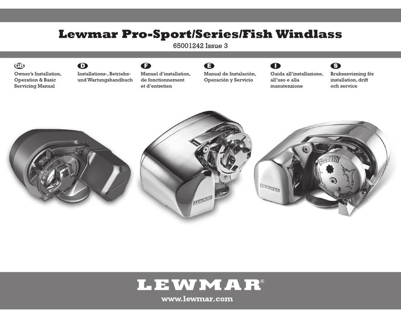
Lewmar Pro Series User manual

Pro-Series /Fish Windlasses
Product manual
Owners Installations, Operation & servicing manual
Installations, Betriebs & Wartungshandbuch
Manuel d’installation, de fonctionnement et d’entretien
Manual de instalación, Operación y servicio
Guida all’installazione, all’uso e alla manutenzione
Bruksanvisning för installation, dri och service
GB
D
I
E
F
S

2
1- Introduction
Thank you for choosing Lewmar. Lewmar products are world renowned for their quality, technical innovation and
proven performance. With a Lewmar product you will be provided with many years of outstanding service.
Product support
Lewmar products are supported by a worldwide network of distributors and Authorised Service Representatives.
If you encounter any difficulties with this product, please contact your national distributor, or your local Lewmar
dealer. Details are available at: www.lewmar.com
CE Approvals
For CE approval certificates contact Lewmar.
Important information about this manual
Throughout this manual, you will see safety and product damage warnings.
You must follow these warnings carefully to avoid possible injury or damage.
2- Specification
A
B
C
P
W
D
D (mm) D (inch) P (mm) P (inch) W (mm) W (inch)
Dual Gypsy 12 mm (
1
/
2
”)
3 Strand and 8 Plait
6mm DIN 766 6 0.236 18.5 0.728 20.4 0.803
7 mm DIN 766 7 0.276 22 0.866 23.8 0.937
1
/
4
” ISO G4 7 0.276 21.3 0.840 24.4 0.962
1
/
4
” BBB 7.14 0.281 22.1 0.870 25.2 0.992
RC0860
Gypsy No. 504
14-16 mm (
9
/
16
”-
5
/
8
”)
3 Strand and 8 Plait
(
5
/
8
” only)
8 mm DIN 766 8 0.315 24 0.945 27.2 1.070
8 mm ISO 4565 8 0.315 24 0.945 28.8 1.134
5
/
16
” BBB 8.73 0.343 25.4 1.000 30.1 1.186
RC0864
Gypsy No. 516
14-16 mm (
9
/
16
”-
5
/
8
”)
3 Strand and 8 Plait
(
5
/
8
” only)
8 mm DIN 766 8 0.315 24 0.945 27.2 1.070
8 mm ISO 4565 8 0.315 24 0.945 28.8 1.134
5
/
16
” ISO G4 8.36 0.329 26.16 1.030 28.4 1.118
Pb Gypsy 14-16 mm Lead-core line
Electric specifications
A B C
mm in mm in mm in
146 5
3
/
4
245 9
5
/
8
178 7
MODEL MAX CHAIN
MOTOR
SUPPLY
MOTOR
POWER MAXIMUM PULL
MAXIMUM
LINE SPEED
WORKING
LOAD LIMIT
NORMAL
CURRENT
DRAW
CIRCUIT
BREAKER WEIGHT
mm in Voltage Watt kg lb m/min. ft/min. kg lb Amp Amp kg lb
Pro-series/Fish 700 7 ¼ 12 500 320 700 32 105 79 175 35 50 8.5 19
Pro-series/Fish 1000
Pro-Fish Pb
8⁵/₁₆ 12 700 454 1000 32 105 114 250 50 70 9.5 21
GB

Lewmar Pro-Series/Fish windlass ref B10490 iss.2 | 3
WARNING!
3- Safety Notice
IMPORTANT: Read these notes before continuing.
3.1 Windlass general
At all times it is the responsibility of the boat user to ensure that the anchor and rode are properly stowed for
the prevailing sea conditions. This is particularly important with high-speed powerboats, because an anchor
accidentally deploying while under way can cause considerable damage. An anchor windlass is mounted in the
most exposed position on a vessel and is thus subject to severe atmospheric attack resulting in a possibility of
corrosion in excess of that experienced with most other items of deck equipment. As the windlass may only be
used infrequently, the risk of corrosion is further increased. It is essential that the windlass is regularly exam-
ined, operated and given any necessary maintenance.
Please ensure that you thoroughly understand the operation and safety requirements of the windlass before
commencing the installation. Only persons who are completely familiar with the controls and those who have
been fully made aware of the correct use of the windlass should be allowed to use it. If there is any doubt of how
to install or operate this unit please seek advice from a suitably qualified engineer.
• Windlasses used incorrectly could cause harm to equipment or crew.
• Windlasses should be used with care and treated with respect.
• Boating, like many other activities can be hazardous. Even the correct selection, maintenance and use of
proper equipment cannot eliminate the potential for danger, serious injury or death.
• Lewmar windlasses are designed and supplied for anchor control in marine applications and are not to be
used in conjunction with any other use.
• Keep limbs, fingers, clothing and hair clear of windlass and anchor rope/chain and anchor during operation. Severe
bodily harm would result.
• Ensure there are no swimmers or divers nearby when dropping anchor.
• When the Windlass is not in use the anchor must be tied off onto a cleat or equivalent strong point to prevent
damage to the boat.
• Windlass must not be used as the sole means of securing the anchor to the bow fitting especially under storm
conditions. Anchors should be independently secured to prevent accidental release.
• Classification Societies require that a vessel lying at anchor must have its anchor rope/chain secured to a chain
stopper or other suitable independent strong point.
• A windlass should never be used as a mooring bollard, the anchor rode MUST be secured to a mooring cleat,
chain stopper or other designated strong point. Using the windlass to secure the rode will damage the
windlass.
• Do not use windlass for ANY purpose other than deployment and recovery of anchor.
• Do not wrap chain around a capstan barrel or drum where fitted.
• A circuit breaker/isolator should always be used with this windlass to protect the motor and cables from
overheating and damage.
• Always switch off this windlass at the circuit breaker/isolator when not in use.
• It is the unavoidable responsibility of the owner or master or other responsible party to assess the risk of any
operation on the vessel.
• Windlass must not be operated whilst under the influence of alcohol or drugs.
3.2 Fitting
• This equipment must be installed and operated in accordance with the instructions contained in this manual.
Failure to do so could result in poor product performance, personal injury and/or damage to your boat.
• Consult the boat manufacturer if you have any doubt about the strength or suitability of the mounting
location.
3.3 Electrical
• Make sure you have switched off the power before you start installing this product.
• This product requires installation by a suitably qualified electrical engineer.
4
4- Installation
4.2 Accessories
Use only genuine Lewmar parts and accessories to ensure top performance and eliminate the risk of voiding your
warranty. For replacement parts, please visit your dealer or www.lewmar.com
4.3 Gypsy Suitability
Gypsies fitted to the Pro-Series / Pro-Fish windlasses are ideally suited to handling our factory made Rope/Chain
combination rodes, which consist of rope spliced to a chain tail. See §2 Specifications for details.
Ropes used must be windlass grade, medium lay nylon. Ropes from different manufacturers have wide variations
in stretch and consistency in diameter. Therefore, rope and chain from other manufacturers may require some
experimentation to determine the optimum size.
Should you have difficulty in matching a gypsy to your chain please consult your local agent or our international
network of distributors.
4.4 Above deck preparation
IMPORTANT - Plan location carefully and allow for the following:
25-60 mm
1” - 21/4”
2
13
1. Use drilling template provided and choose an appropriate position with reference to the vessel’s bow roller
and the chain locker below. Allow for the rotation of the manual operating wrench handle
2. If the deck is not flat, a suitable mounting pad may be required to take up camber or sheer.
NOTE: If in doubt about the suitable construction of the pad consult a qualified marine engineer.
The deck is an integral component of the windlass it has to secure the windlass and be strong enough to
cope with the high torque stresses involved in recovering the anchor. Decks that are thin, or of foam or balsa
laminate construction, will require reinforcement in order to spread the loads that will be applied to the deck
while the windl;ass is in use.
3. Lewmar recommends a minimum deck thickness of 25mm (1”),
M8 Studs suit deck and packing thickness of 25-60mm (1” - 21/4”).
300 mm
(12”)
6°
WINDLASS INSTALLATION
• An appropriate marine sealant
• Electric drill and 10mm (3/8”) drill bit
• 76mm (3”) Hole Saw
WIRING INSTALLATION
• Crimping Pliers / Wire Stripper
• Suitable electrical cable and crimp terminals
4.1 Basic requirements
Each installation requires the following tools:
4.5 Below deck preparation
IMPORTANT: The positioning of the windlass must be
checked prior to cutting for deck/hull and bulkhead clearance.
Lead from the roller should be fed horizontally back to the
top of the gypsy and along its centre line within +6˚. There
must be sufficient vertical fall (minimum of 300 mm /12” at
all times) for the chain or
rope when hauling in. WARNING! Failure to pro-
vide minimum vertical fall
will cause jamming.
GB

Lewmar Pro-Series/Fish windlass ref B10490 iss.2 | 5
4.6 Above deck fitting
Using the template and aer you have checked all the above and below deck requirements cut the following
holes:
Using a 10mm (3/8”) diameter drill bit, make the three holes for the mounting studs and two for the motor
cables. With a 76mm (3”) diameter hole saw, make one hole for the rode to pass through.
1. When all the holes have been made, remove the template. To help avoid water absorption by the deck, apply
an appropriate marine sealant to the freshly cut hole edges.
2. Assemble and tighten studs into base until they bottom out in their holes. Studs have a flat for spanner loca-
tion. Position the flats of the studs nearest the base of the windlass.
3. Place the base mat in position on the deck. Optionally, apply a suitable sealant to the base of the windlass,
any mounting pad or around the studs.
2
13
4.7 Under deck fastening
1. Fit windlass to deck. Trim the studs back to 6mm (1/4”) below
the fully tightened nuts to prevent snagging anchor rope/chain if
necessary.
NOTE: If using silicone or other rubbery type sealant, it is advisable
to allow curing of the sealant before final tightening of the mount-
ing nuts.
6mm - 1/4”
ON
4.8 Loading rope/chain
For safety and performance Lewmar recommends the use of matched Lewmar anchor rodes.
123 4
DO NOT use a permanent
adhesive/sealant eg.5200
WARNING! Isolate (turn off) the wind-
lass using circuit breaker / isolator.
1. Pull out control arm.
2. Feed anchor rope/chain into entry hole. Tie off to suitable strong point in the anchor locker.
3. Align rope/chain in gypsy. Release control arm and wrap rope/chain around gypsy.
4. Turn on the breaker and power load rest of anchor rope/chain.

6
5- Electrical wiring
MODEL 700 CABLE SELECTION
Cable length
up to
Feet 7 13 20 26 33 40 46 53 60 66 73 80
Metres 2 4 6 8 10 12 14 16 18 20 22 24
Cable Size AWG 8 6 4
mm²10 16 25
MODEL 1000 CABLE SELECTION
7 13 20 26 33 40 46 53 60 66 73 80
2 4 6 8 10 12 14 16 18 20 22 24
6 4 2
16 25 35
5.1 Electric cable selection
Lewmar recommends the installer source and install cable that meets the requirements of the standards and
regulations relevant to the installation and codes of practice.
The cable table gives recommended cable sizes based on total length of
cable required, from the battery, following the route of the cables.
5.2 Wiring
Plan the installation to suit the controls and give the operator a full view of the windlass. The wiring system
should be of the fully insulated type, which avoids possible electrolytic corrosion problems. We recommend the
use of type III stranded, tinned copper wire with copper crimp terminals. Most modern installations are negative
return (negative ground) but polarity should be checked.
Overload protection, in the form of the circuit breaker provided must be built into the windlass wiring circuit.
• Circuit breaker supplied:
Pro-Serie/Fish 700 - 50A (Part No 68000348)
Pro-Serie/Fish 1000 and Pro-Fish Pb - 70A (Part No 68000240)
• The circuit breaker should be positioned close to the battery in a dry, readily accessible place.
• The breaker must be manually reset should an overload occur that causes it to trip to the off position.
• If you are not sure you understand these guidelines, seek professional help. Ensure that the installation
complies with USCG, ABYC, NMMA or other local regulations.
WARNING!
5.3 Control switch installation
The unit is supplied with
• Guarded rocker switch (product ref 68000593)
• Contactor (product ref 68000939)
Follow the wiring diagram § 5.4
NOTE: Optional electric footswitches and remote handheld control available.
Visit www.lewmar.com for more information
Contactor box and control box used in some installation refer to wiring diagram
§ 5.5 and § 5.6
Optional wireless remote also available
See table below for models and references
WIRELESS REMOTE
3 BUTTON WINDLASS ONLY
WIRELESS REMOTE
5 BUTTON WINDLASS & THRUSTER
68000967 68000968
Windlass performance is directly related to cable size and length. Voltage drop over the complete wiring run
must not exceed 10%.
NOTE: In a multi station installation all switches must be wired in a parallel circuit.
GB
DO NOT confuse cable length
with the length of the vessel

Lewmar Pro-Series/Fish windlass ref B10490 iss.2 | 7
5.4 Wiring diagram using contactor provided (Part No 68000939)
Installation instructions are supplied separately with any accessories.
ON
A
B
Electric Switches
(See www.lewmar.com)
UP DOWN
Remote Handheld Control
(See www.lewmar.com)
Rocker Switch
(68000593)
UP DOWN
Circuit Breaker
(See § 4.2)
Battery
12 VDC
Contactor
(68000939)
Fuse
3 A
Cable Colours
A = Black
B = Red
Switch wire thickness: 1.5 mm2 (16 AWG)
Optional accessories
Optional Wireless
Control Available
(See § 5.3)

8
5.5 Wiring diagram if a contactor box (Part No 68000965) is used
Installation instructions are supplied separately with any accessories.
ON
A
B
Circuit Breaker
(See Chart)
Battery
12 VDC
Contactor Box
(68000965)
Fuse
3 A
Rocker Switch
(68000593)
UP DOWN
Remote Handheld Control
(See www.lewmar.com)
Electric Switches
(See www.lewmar.com)
UP DOWN
Cable Colours
A = Black
B = Red
Switch wire thickness: 1.5 mm2(16 AWG)
Optional accessories
Optional Wireless
Control Available
(See § 5.3)
GB

Lewmar Pro-Series/Fish windlass ref B10490 iss.2 | 9
5.6 Wiring diagram if a pre-wired control box (Part No 68000963) is used
Installation instructions are supplied separately with any accessories.
ON
A
B
Pre-Wired
Control Box
(68000963)
Rocker Switch
(68000593)
UP DOWN
Remote Handheld Control
(See www.lewmar.com)
Electric Switches
(See www.lewmar.com)
UP DOWN
Circuit Breaker
(See § 4.2)
Battery
12 VDC Cable Colours
A = Black
B = Red
Switch wire thickness: 1.5 mm2(16 AWG)
Optional accessories
Optional Wireless
Control Available
(See § 5.3)

10
6- Operation
WARNING! Trapping, crushing or
entanglement danger whiIst operating
windlass manually or under power
1. Disengage the capstan drive by pressing the plunger button on the capstan drive cap and pressing the locking
button until the plunger remains in the down position.
2. Release any anchor locks
3. When safe insert the Lewmar wrench in to the capstan drive cap. Rotate clockwise to grip the gypsy and
anticlockwise to free the gypsy controlling the rate of descent of the
anchor. Once deployed adjust desired scope if using a rope/chain, lock
the clutch by turning the drive cap clockwise and engage the anchor
locks. Remove the wrench handle.
4. To return the windlass back to powered operation pull the locking button out disengaging the plunger.
Engage the circuit breaker/isolator and press the UP/DOWN button.
13 4
6.1 Manual controlled freefall
Use this method for quicker anchor deployment, in an emergency involving loss of power or to save battery
power. Observe maritime anchor deployment safety rules.
1. Release any anchor locks
2. When safe, insert the Lewmar wrench in to the capstan drive cap. Rotate clockwise to grip the gypsy and an-
ticlockwise to free the gypsy controlling the rate of descent of the anchor. Lock the clutch by turning the drive
cap clockwise and engage the anchor locks.
3. To return the windlass back to powered operation lock the clutch by
rotating the capstan drive cap clockwise until tight and remove the
wrench handle.
4. Engage the circuit breaker/isolator and press the up button.
5. NOTE: If the clutch nut is not tight the internal clutch mechanism will rotate freely and not engage the drive to
the capstan.
ON
12 3 4
6.1a - Pro-Fish
6.1b - Pro-Series
2
See §6.3 for powered operation
WARNING! Isolate (Turn off) the wind-
lass using circuit breaker / isolator.
GB
WARNING! Always remove
wrench handle after use
WARNING! Always remove
wrench handle after use

Lewmar Pro-Series/Fish windlass ref B10490 iss.2 | 11
6.3 Power up/down
To release anchor:
1. Check unit is not in manual mode and plunger is disengaged/up position.
2. Release any anchor locks.
3. Engage the circuit breaker/isolator.
When releasing the anchor, press DOWN button for 2 seconds until the anchor is under freefall. If the clutch was
le in a locked position the anchor will move almost immediately, if unlocked it could take several seconds to
fully re-engage the internal clutch.
NOTE: Pressing the DOWN button for over 5 seconds will result in a longer clutch re-engagement time during
the next UP command).
If using a rope/chain rode, motor astern to create the desired scope. Once scope has been created press the UP
button continuously until freefall stops. It normally takes several seconds to fully re-engage the internal clutch
mechanism, locking the windlass.
NOTE: Failure to lock the windlass clutch could result in rope/chain creeping out.
To retrieve anchor:
4. Press the UP button continuously to retrieve the anchor.
ON
2 Sec
ON
123 4
6.2 Manual anchor recovery
1. Ensure capstan drive cap is tight so the clutch is locked.
2. Release any anchor locks and when safe insert the Lewmar wrench or a standard 12mm (1/2”) drive rachet
into the socket end of the drivesha on the opposite site of the windlass to the gypsy.
3. Using the wrench, turn the drivesha clockwise to retrieve the anchor.
4. Once anchor is retrieved, remove the wrench handle and ensure it is
adequately secured to an independent strong point.
1 2 3 4
WARNING! Isolate (Turn off) the wind-
lass using circuit breaker / isolator.
WARNING! Trapping, crushing or
entanglement danger whiIst operating
windlass manually or under power
6.3a - Pro-Fish
WARNING! Always remove
wrench handle after use

12
To release anchor:
1. Check clutch nut is tight. If the clutch nut is not
tight the internal clutch will rotate freely and not
engage the drive to the capstan.
2. Release any anchor locks.
3. Engage the circuit breaker/isolator.
Press DOWN button.
To retrieve anchor:
4. Press the UP button continuously to retrieve the
anchor.
Note: If the clutch nut is not tight the internal clutch
will rotate freely and not engage the drive to the
capstan.
ON
ON
1 2 3 4
6.3 b - Pro-Series
GB
When anchoring, power rode out allowing the vessel to take up stern away preventing the rode tangling with
anchor. Use this method for mooring stern first to a jetty.
6.4 Windlass operating procedures
This is an anchor recovery device. DO NOT use the windlass to pull the boat to the anchor as it will damage the
mechanism. Vessels at anchor will snub on the rode and this can cause slippage or apply excessive loads to the
windlass. Best practice is to use a bollard or other strong point when at anchor and use the vessels engines to
break the anchor free. Otherwise excessive load will cause the freefall function to seize and can cause damage
to the gearbox.
To aid recovery, under power, move vessel
towards anchor but not over and beyond, as
this can cause damage to topside.
As anchor approaches the vessel use careful
adjustments of controls to avoid damaging
vessel, start and stop the windlass to bring the
anchor slowly into the bow roller.
Pulling the last bit of rode and anchor into the
bow roller at full speed can damage the boat,
bow roller and windlass.
When stowing it is important to make sure, particularly with rode lines that there is at least 300mm (12”) of
free space below the windlass (See §4.5). Stop and check during the stowing process to determine if there is
sufficient space on you vessel. If the rode pile is too close to the underside of the windlass, re-distribute the rode
away from directly below the windlass. If the rode gets too close to the underside of the windlass it will cause
problems with good rode recovery and may cause damage to the line.
When retrieving anchor do not
overload or stall in windlass.
The rode should be secured directly to a bollard, sampson
post or cleat and a chain secured by a chain stopper.

Lewmar Pro-Series/Fish windlass ref B10490 iss.2 | 13
7- Servicing
7.1 Servicing schedule
The service period is determined by the frequency of use. Professional user will need to carry out these opera-
tions more oen than the weekend user. Before commencing any work on this or any other electrical product,
isolate from the power source.
Bedding in period:
When new there are some areas that will need frequent checking. If no movement is found they can be inspected
less oen.
• Examine all electrical connections, to make sure they are sound and corrosion hasn’t set in.
Tighten if necessary and protect if required.
• Check mounting studs are firmly clamped and tighten if required.
Aer use:
• Wash down the windlass using fresh water.
• Ensure rode is at least 12” (300mm) below the windlass
• Check anchor locker drain
• Check rode and splice for wear.
Annually or more oen if frequent user:
• Examine all electrical connections, to make sure they are sound and corrosion hasn’t set in. Tighten if
necessary and protect if required.
• Check mounting studs are firmly clamped and tighten if required.
• Check rode and splice for wear.
• Check gypsy as it is a high wear item (For service and replacement see §7.2)
• Check main case (19) for damage particularly around the seal (24) and cover (18)
WARNING! Isolate the windlass
using circuit breaker/isolator
WARNING! Ensure rode is adequately
secured to an independent strong point
7.2 Gypsy replacement/service
1. Remove shoulder screw (17) from drive cap (8) this may required warming as it is secured with loctite®
2. Unscrew and remove clutch nut (36) and gypsy cone (35).
3. Unscrew blots (53) and (54) they may require warming as they are secured with loctite®and remove stopper
cam (9) (Pro-Fish only) and rope guard (29), careful not to loose spacer (31).
• Slide away stripper (37) to remove from gypsy (58)
• Pull back control arm (30) away from the gypsy and remove gypsy and drive pins (43), take care to note
direction of rope teeth for reassembly and keep the pins safe.
• Check parts for wear and replace as appropriate
• Clean thoroughly without solvent or wire brush and dry.
• Clean and lubricate Pro-Fish plunger.
• Re-Assemble, use grease to hold the drive pins (43) in place and small amount on the mating faces.
• Use loctite®on the screws (53) and (54) and Pro-Fish cap screw (17), making sure no Loctite residue gets on
the thread as it will prevent the free fall function operating.
1 2 3
Pro-SeriesPro-Fish
Pro-Fish Pro-Series

14
7.3 Parts list
55
42
18
25
4
251
27
46
22
5
3
39
19
21
28
50
47
43
9
54
35
36
17
16
11
10
14
20
12
815
29
37
40
44
41
38
45
30
48
58
13
53
3154
32
49
1
7
57
24
52 33
6
34
23
6
26
56
Pro-Fish
Pro-Series
GB

Lewmar Pro-Series/Fish windlass ref B10490 iss.2 | 15
KIT NO DESCRIPTION ITEMS INCLUDED QTY
66000096 Pro-Series Stripper Arm Kit 37(1), 53(1), 54(2)
66000098 Pro-Series Clutch Nut & Cone Kit 35(1), 36(1), 43(2)
66000099 Clutch Lever Clutch lever (not shown)
66000101 504 Gypsy RC 8mm (5/16”) 58A(1)
66000102 516 Gypsy RC 5/16” G4 58B(1)
66000768 Pb Gypsy (14-16mm Leaded Line) 58C(1)
66000769 Dual Gypsy RC 6mm - 7mm -¼” 58(1)
66000634 Bearing Kit 2(1), 4(1), 5(1), 6(2), 56(1), 57(1)
66000616 Pro-Fish Conversion Kit 8(1), 9(1), 10(1), 11(1), 12(1), 13(1),14(1), 15(1), 16(1), 17(1), 20(1), 54(2)
66000617 Pro-Fish Stopper Kit 9(3), 54(2)
66000620 Pro-Fish Drive Cap Assembly Kit 8(1), 10(1), 11(1), 12(1), 13(1),14(1), 15(1), 16(1), 17(1), 20(1)
66000758 Pro-Series Washer Kit 21(1), 22(1), 23(2), 27(1)
66000759 Pro-Series Gasket Kit 24(1), 25(6)
66000760 Pro-Series Coumpound Gear kit 5(1)
66000761 Pro-Series Gears & Shaft Kit 2(1), 3(1), 6(2), 23(2), 28(1), 33(1), 34(1), 45(1), 46(1), 51(1)
66000762 Pro-Series Gear Train Cover Kit 4(1), 18(1), 24(1), 25(6). 42(1), 55(6), 57(1)
66000763 Pro-Series 12V Motor Kit 26(1), 33(1), 38(1), 45(1), 50(2), 52(3)
66000764 Pro-Series Seals & Screw Kit 2(1), 3(1), 7(1), 24(1), 25(6), 26(1), 39(2), 42(1), 43(2), 45(1), 52(3), 53(2), 54(3), 55(6)
66000766 Pro-Guard / Control Arm Kit 29(1), 30(1), 31(1), 41(1), 44(1), 48(1), 54(3)
1. Anchor rode pays out independently while windlass is not in use.
• This problem is a result of not securing the anchor rode combined with the gypsy drive cap being slack.
Tighten the gypsy drive cap using the winch handle and always secure the anchor rode independently of the
windlass when not in use.
2. Failure to operate or sluggish operation.
• The majority of these problems are electrical in nature. It is essential that the proper voltage be maintained.
The proper voltage on a 12 Volt system is 13.5 Volts, constant low voltage will damage motor.
• Ensure electrical cable size is large enough to handle the current draw and keep voltage drop within
acceptable limits.
• Check control switches, connections, battery condition, isolator switch, fuse and motor for operation failure.
3. Failure to operate.
• Is there a voltage at the input terminals to the contactor and switches. Check the circuit breaker/isolator
switch and any fuses.
• Operate the switch. Is there voltage at the positive switch terminal on the solenoid. If not, the switch (or its
wiring), is difective.
• Keep the switch activated. Is there voltage at the main output terminal on the contactor. If not check the
contactor coil ground circuit. If okay, replace the contactor.
• Check the voltage at the motor. If voltage of at least 12.5 volts is present and the motor does not operate, the
motor is defective.
8- Troubleshooting

Lewmar Pro-Series/Fish windlass ref B10490 iss.2 | 61
1- Introduktion
Vi tackar för att du valt en produkt från Lewmar! Lewmars produkter är kända över hela världen för sin
höga kvalitet, långt framskridna teknik och beprövade prestanda. En produkt från Lewmar ger dig många års
problemfri tillvaro.
Produktsupport
När du köper våra produkter får du också tillgång till vårt världsomspännande nätverk med distributörer och
auktoriserade serviceverkstäder. Om du skulle få problem med produkten kontaktar du bara din lokala åter-
försäljare eller din distributören i ditt land. Information om detta hittar du på vår webbsida:
www.lewmar.com
CE-märkning
Överensstämmelsedeklaration enligt EU kan beställas från Lewmar.
Viktig information om den här handboken
I den här handboken använder vi symboler för att markera viktig säkerhetsinformation. Läs och ta hänsyn till
dessa varningar, för att undvika person- och sakskada.
2- Tekniska specifikationer
A
B
C
Elspecifi kationer
A B C
mm in mm in mm in
146 53/4245 95/8178 7
MODELL MAX CHAIN
MOTOR
SUPPLY
MOTOR
POWER
MAX
DRAGKRAFT
MAX
LINHASTIGHET
WORKING
LOAD LIMIT
NORMAL
DRIFT
STRÖM
KRETS
BRYTARE VIKT
mm in Voltage Watt kg lb m/min. ft/min. kg lb Amp Amp kg lb
Pro-series/Fish 700 7 ¼ 12 500 320 700 32 105 79 175 35 50 8.5 19
Pro-series/Fish 1000
Pro-Fish Pb
8⁵/₁₆ 12 700 454 1000 32 105 114 250 50 70 9.5 21
P
W
D
D (mm) D (inch) P (mm) P (inch) W (mm) W (inch)
Dual
Kättinghjul
12 mm (1/2”)
3 Strand and 8 Plait
6mm DIN 766 6 0.236 18.5 0.728 20.4 0.803
7 mm DIN 766 7 0.276 22 0.866 23.8 0.937
1/4” ISO G4 7 0.276 21.3 0.840 24.4 0.962
1/4” BBB 7.14 0.281 22.1 0.870 25.2 0.992
RC0860
Kättinghjul
No. 504
14-16 mm (9/16”-5/8”)
3 Strand and 8 Plait
(5/8” only)
8 mm DIN 766 8 0.315 24 0.945 27.2 1.070
8 mm ISO 4565 8 0.315 24 0.945 28.8 1.134
5/16” BBB 8.73 0.343 25.4 1.000 30.1 1.186
RC0864
Kättinghjul
No. 516
14-16 mm (9/16”-5/8”)
3 Strand and 8 Plait
(5/8” only)
8 mm DIN 766 8 0.315 24 0.945 27.2 1.070
8 mm ISO 4565 8 0.315 24 0.945 28.8 1.134
5/16” ISO G4 8.36 0.329 26.16 1.030 28.4 1.118
Pb Kättinghjul 14-16 mm Blyad lina
S

62
VIKTIGT : Läs dessa anvisningar innan ni fortsätter.
3.1 Ankarspel
Klassningssällskapen och Lewmar kräver att ett fartyg till ankars alltid har kättingen/linan låst med kätting-
stopp/linlås eller annan tillräckligt stark låsning!
Det är alltid befälhavaren ombord som ansvarar för att ankaret och kättingen/ linan är stuvad på ett för rådande
sjöförhållanden säkert sätt. Detta är särskilt viktigt på snabbgående motorbåtar, eersom ett ankare som går
i sjön under gång kan orsaka allvarliga skador. Ankarspel monteras på den mest utsatta platsen ombord och
utsätts för svåra förhållanden, som kan leda till korrosion av en grad som man inte hittar på annan däcksutrust-
ning. Eersom ankarspel för det mesta inte används särskilt oa blir risken för korrosion oast större. Det är
också därför det är viktigt att ankarspelet inspekteras och körs regelbundet och att underhållet sköts korrekt.
Se till att du förstår de dri- och säkerhetskrav som gäller för ankarspelet innan du påbörjar installationen. Låt
endast personer med god kännedom om och vana vid den här typen av kontroller och som är fullt införstådda
med hur spelet skall hanteras använda det. Vid tveksamheter om installation eller användning av spelet bör man
alltid ta hjälp av kompetent tekniker.
• Felatkig hantering av ankarspel kan leda till skador på både besättning och utrustning.
• Ankarspel skall användas med iakttagande gott sjömanskap och sunt förnuft.
• Båtlivet kan, precis som andra aktiviteter, vara farligt. Inte ens rätt val, underhåll och användning av
utrustningen kan undanröja risken för fara, svår personskada och till och med dödsfall.
• Våra ankarspel är konstruerade och levererade för ankarhantering i marin miljö och skall inte användas i andra
sammanhang.
• Se till att du inte fastnar med kroppsdelar, fi ngrar, kläder eller hår i spelet, linan/kättingen eller ankaret när du använder
ankarspelet. De skador som uppstår om du skulle fastna kan bli mycket svåra.
• Kontrollera alltid att inga badare eller dykare befi nner sig i närheten du fäller ankaret.
• Ankaret skall alltid vara surrat när det inte används, för att förhindra skador på båten pga ankarets rörelser vid t ex
sjöhävning.
• Ankaret får inte vara surrat enbart i spelet, framför allt inte vid hård vind. Ankaret skall hållas surrat på ett sådant sätt att
det inte kan gå i sjön oavsiktligt.
• Klassningssällskapen kräver att ett fartyg till ankars alltid har kättingen/ linan låst med ett separat kättingstopp/ linlås
eller annan tillräckligt stark låsning.
• Ett ankarspel ska aldrig användas för förtöjning. Ankarlinan/kättingen måste säkras i en starkare
förtöjningsplats som knap, kättingstopp eller annan för ankring avsedd fastsättning. Att använda ankarspelet
för att säkra lina/kätting kommer att skada spelet.
• Ankarspel får inte användas till något annat än att sätta och lätta ankaret.
• Kättingen får inte läggas runt en capstan eller lintrumma.
• Spelet skall alltid anslutas elektriskt via brytare med överlastskydd, för att skydda motor och kablar för
överhettning och annan skada pga av överlast.
• Brytaren skall alltid vara frånslagen när spelet inte används.
• Tänk på att det alltid är befälhavaren som ansvarar för säkerheten ombord.
• Ankarspelet får inte hanteras av person som är påverkad av alkohol eller andra droger.
3.2 Montering
• Den här utrustningen måste installeras och användas i enlighet med instruktionerna i den här handboken.
Underlåtenhet att följa dessa instruktioner kan leda till bristfällig funktion, personskada och/eller skada på
din båt.
• Rådgör med den som byggt din båt om du har några funderingar kring hållfasthet och stabilitet på
monteringsplatsen.
3.3 Elsystem
• Kontrollera att du brutit strömförsörjningen innan du påbörjar installationen.
• Det här ankarspelet skall kopplas in av kvalifi cerad elektriker.
VARNINGAR!
3- Introduktion
S

Lewmar Pro-Series/Fish windlass ref B10490 iss.2 | 63
4- Installation
4.2 Tillbehör
Använd bara reservdelar och tillbehör från Lewmar, så säkerställer du bästa tänkbara funktion och undanröjer
risken att garantin upphör att gälla. Reservdelar köper du lämpligast hos din återförsäljare eller på vår webbsida
www. lewmar.com
4.3 Kabelarets användningsområde
Kabelaren på ankarspelen i serierna Pro är idealiska för våra egna ankarlinor som är splitsade mot kätting i ena
änden. Mer information fi nns i de tekniska specifi kationerna.
Ankarlinan måste vara avsedd för ankarspel och tillverkad av medelgrov nylon. Linor från andra tillverkare
varierar mycket vad gäller töjning och diameternoggrannhet. Det kan därför hända att man måste prova lina och
kätting från andra tillverkare för att hitta optimal grovlek.
Om du har problem med att hitta ett kabelar som passar din kätting, kan du vända dig till din lokale återförsäl-
jare för att få hjälp.
4.4 Installationsförberedelser på däck
VIKTIGT! Välj monteringsplatsen noggrant och följ nedanstående riktlinjer:
25-60 mm
1” - 21/4”
21 3
1. Använd hålmallen som medföljer och bestäm var det bäst skall monteras för att passa mot ankarstävrullen,
kättingboxen och spaken för manuell användning. Välj om möjligt en plats där däcket är så plant som möjligt.
2. Om däcket inte är plant, kan lämpligt mellanlägg behövas för att få jämn fördelning på kraerna.
ANM: Rådfråga en kvalifi cerad båtbyggare vid tveksamheter om hur mellanläggen bör se ut.
Tunna däck och laminatdäck fyllda med skum eller balsa måste förstärkas för att fördela de kraer som verkar
på däcket när spelet används.
3. Vi rekommenderar en minsta däckstjocklek på 25mm,
M8-pinnbultar tillräckligt långa för däckets tjocklek och mellanlägg på 25-60mm.
300 mm
(12”)
6°
ANKARSPEL
• Lämpligt marint tätningsmedel
• Borr på10 mm
• Hålsågar med diameter 76mm
KABELDRAGNING
• Kabelskotång/avisoleringstång
• Lämplig kabel och passande kabelskor
4.1 Grundläggande krav
Följande behövs för installationen:
4.5 Installationsförberedelser under däck
VIKTIGT! Spelets placering måste kontrolleras
noggrant avseende tillgängligt utrymme innan
du tar hål i däck eller skrov
Linjen mellan rullen och kabelarets ovankant och
längs dess centrumlinje skall vara horisontell +6°.
Det måste fi nnas tillräckligt med vertikalt fall för
kättingen/linan vid hemtagning.
VARNING! Otillräckligt med fallutrymme kan
leda till att kättingen kommer i beknip.

64
4.6 Ovan däck
När alla ovan beskrivna kontroller utförts märker du upp de hål som skall tas upp, med hjälp av mallen.
Borra de tre 10-millimetershålen för pinnbultarna och två för motorkablarna. Såga upp kätting/ linhålet med en
hålsåg med 76mm diameter.
1. Ta bort mallen när alla hål tagits upp. Täta kanterna i de nyupptagna hålen med lämpligt marint tätningsme-
del.
2. Dra i bultarna så att de bottnar i hålen i bädden. Vissa av pinnbultarna är plana i änden.
Dessa pinnbultar skall vara närmast ankarspelets bas.
3. Placera bäddunderlaget på sin plats på däck. Du kan också använda butyltejp, som är ett mycket bra tätnings-
medel som lämpar sig för det mesta på däck.
21 3
ON
4.8 Påkörning av lina/kätting
Av säkerhetsskäl rekommenderar vi att du väljer ankarlina/kätting från Lewmar.
1 2 3 4
4.7 Montering under däck
Ställ spelet på plats på däck. Kapa pinnbultarna så att
de sticker ut högst 6mm ur de fullt åtdragna muttrarna.
OBS! Om du använder silikon eller annat gummiliknande
tätningsmedel, bör du tänka på att man bör låta vissa
sådana tätningsmedel härda innan muttrarna dras åt.
¡ADVERTENCIA! Aislar el molinete con interruptor /
aislador
1. Styrarm för utkörning.
2. Mata in linan/kättingen i ingångshålet. Gör fast linan/ kättingen på tillräckligt kraig plats ankarhållaren.
3. Linjera linan/kättingen i kabelaret. Frigör styrarmen och lägg linan/ kättingen runt kabelaret.
4. Slå på spelet på strömbrytaren och avlasta linan/kättingen.
S
ANVÄND INTE permanenttätningsmedel,
såsom t ex 5200.
6mm - 1/4”

Lewmar Pro-Series/Fish windlass ref B10490 iss.2 | 65
5- Kabeldragning
5.1 Kabeldimensionering
Vi rekommenderar att installationskabeln dimensioneras eer gällande standarder och bestämmelser.
Rekommendationerna i tabellen baseras på kabelns totala längd
från batteriet fram till ankarspelet.
5.2 Kabeldragning
Planera installationen så att den passar kontrollenheterna och operatören får full kontroll över spelet.Kabeln
skall vara en helisolerad, skyddad mot elektrolytisk korrosion.
Vi rekommenderar användning av tvinnad kopparledare av standardtyp klass III, med kabelskor av koppar. De fl
esta moderna installationer är minusjordade, men för säkerhets skull bör polariteten kontrolleras.
Överlastskyddet, dvs den medlevererade kretsbrytaren/ säkringen, skall byggas in i kretsen.
• Medföljande kretsbrytare:
Pro-Serie/Fish 700 - 50A (Art nr 68000348)
Pro-Serie/Fish 1000 and Pro-Fish Pb - 70A (Art nr 68000240)
• Kretsbrytaren bör installeras i ett torrt och lättåtkomligt utrymme, så nära batteriet som möjligt.
• Brytaren återställs manuellt efter aktivering pga överlast.
• Begär professionell hjälp om du inte förstår dessa riktlinjer.
• Installationen måste utföras i enlighet med tillämpliga regler och föreskrifter.
VARNINGAR!
5.3 Installation av huvudbrytare
Denna enhet levereras med
• Vippströmbrytare (68000593)
• Kontaktor (68000939)
Följ kopplingsschemat §5.4 (p.7)
NOT: Som tillval finns elektrisk fotkontroll och handhållen ärrkontroll.
Besök www.lewmar.com för mer information
Kontaktor och kontollenhet används vid vissa installationer, se kopplingsschema §5.5 och §5.6 (p.8-9)
Trådlös Fjärrkontroll finns tillgänglig som tillval. Se nedan tabell för modeller och artikelnummer.
TRÅDLÖS FJÄRRKONTROLL
(3 knappars för ankarspel)
TRÅDLÖS FJÄRRKONTROLL
(5 knappars för ankarspel och
bogpropeller)
68000967 68000968
Ankarspelets funktion är direkt beroende av kabelns tvärsnittsarea och längd. Spänningsfallet över hela ka-
bellängden får inte överstiga 10%.
NOTA: Tänk på att alla brytare i installationer med fl era enheter skall vara kopplade parallellt.
Förutsätt inte att kabellängden är lika
med båtens längd!
MODEL 700 CABLE SELECTION
Cable length
up to
Feet 7 13 20 26 33 40 46 53 60 66 73 80
Metres 2 4 6 8 10 12 14 16 18 20 22 24
Cable Size AWG 8 6 4
mm²10 16 25
MODEL 1000 CABLE SELECTION
7 13 20 26 33 40 46 53 60 66 73 80
2 4 6 8 10 12 14 16 18 20 22 24
6 4 2
16 25 35
Other manuals for Pro Series
1
This manual suits for next models
3
Table of contents
Languages:
Other Lewmar Fishing Equipment manuals