1
THE KEY TO SALON SUCCESS
PRIVE PEDICURE SPA USER MANUAL
RECEIVING AND INSPECTION: If missing parts or damages are found, please notify the carrier at once and
insist on a notation of the damage on the bill of lading. DO NOT DISCARD THE SHIPPING BOX. If you give
the carrier a clear receipt for goods that have been damaged in transit, you do so at your own risk and
expense.
Table of Contents
Identifying Parts for PRIVE® Model 2
WALL CLEARANCE & SPA to SPA RECOMMENDED CLEARANCE 3
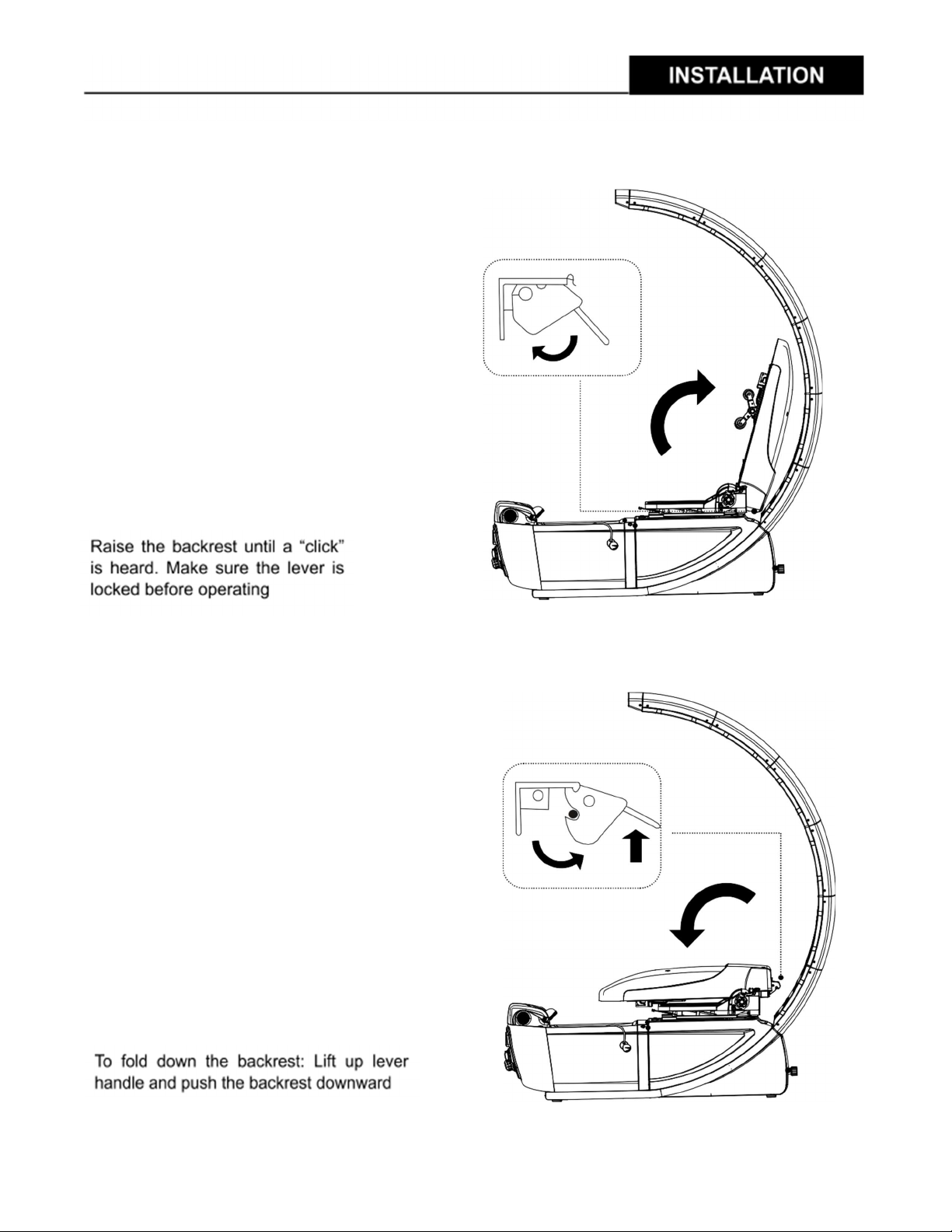
INSTALLATION OF PEDICURE SPA DOME 4
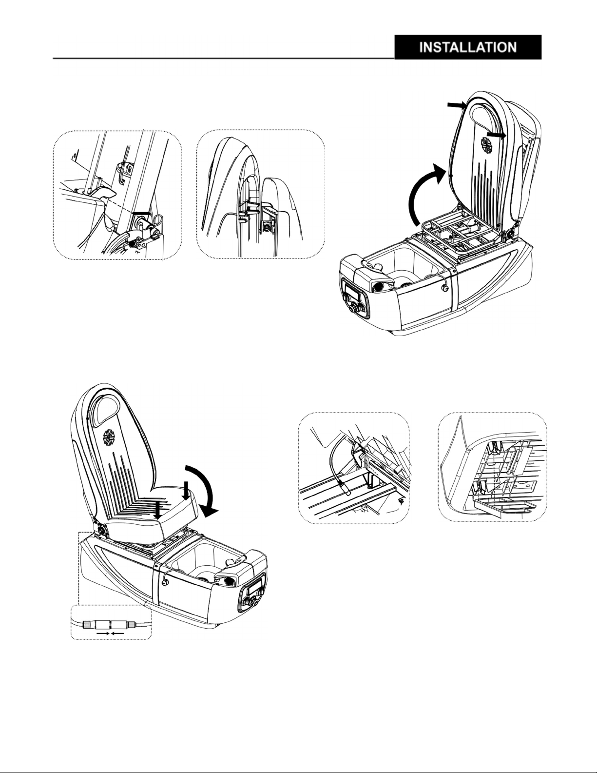
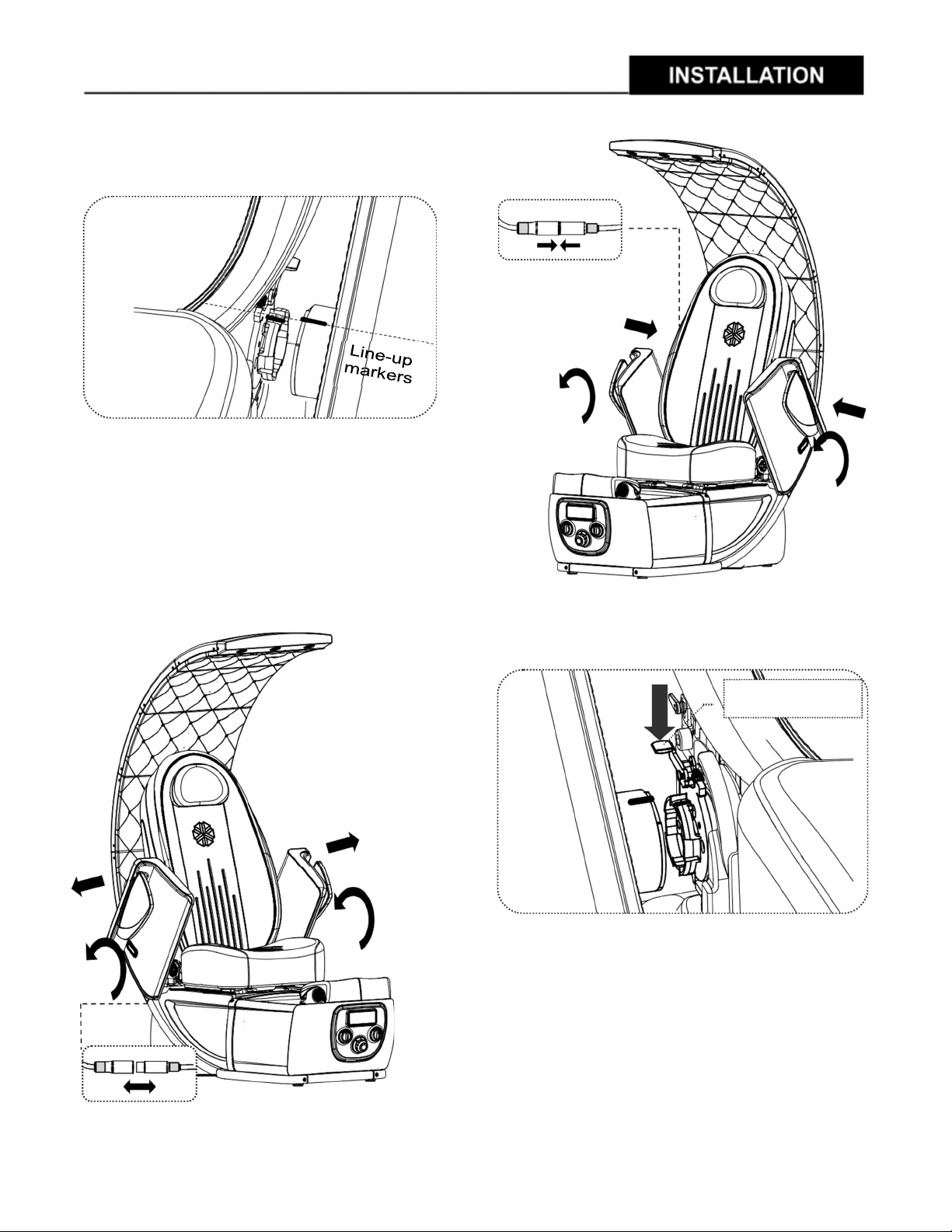
INSTALLATION OF PEDICURE SPA SEAT 5
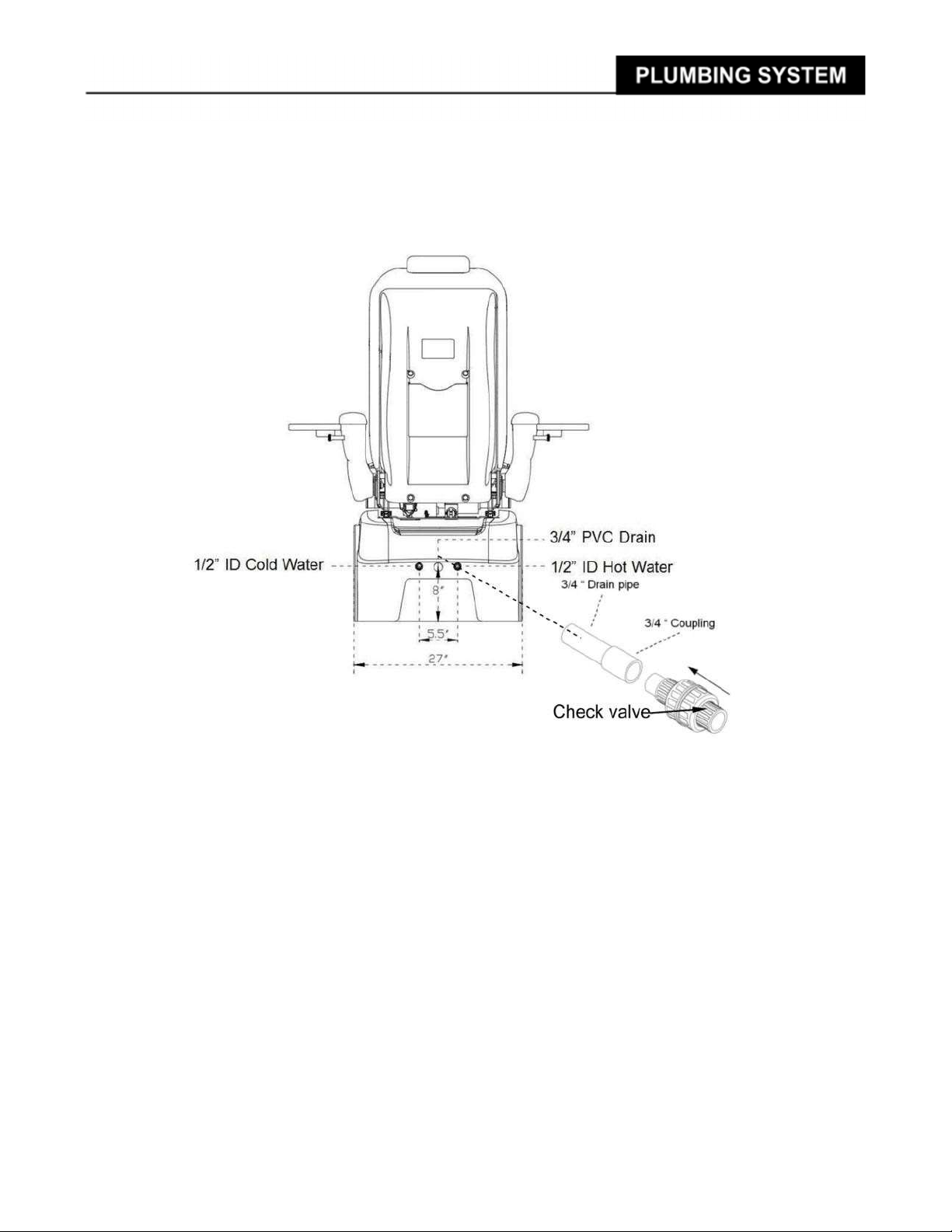
INSTALLATION OF PLUMBING SYSTEM 8
INSTALLATION OF VENTILATION SYSTEM (OPTIONAL) 11
ELECTRICAL AND PEDICURE SPA COMPONENT SPECIFICATIONS 12
PRE-OPERATIONAL SETUP 13
OPERATING Auto-Fill™/Jet Switch: 15
OPERATING DIGITAL CONTROL PANEL: 16
RESET WATER SENSOR AND WATER LEVEL 17
MASSAGE SYSTEM & REMOTE CONTROLLER 19
DOME LED REPLACEMENT 20
STEAMERS REPLACEMENT 21
AF-CONTROL BOX REPLACEMENT 22
WARNING: 1. This Product is for indoor use only & is not recommended for use on Carpet or Wood floor
2. This Product must be connected to a circuit outlet protected by a Class A GFCI
3. DO NOT USE if you have poor circulation, or if any area of your feet or legs has an open sore
4. Maximum temperature of the water should never exceed 100 degrees F.
5. DO NOT STEP/ STAND IN THE FOOT BASIN.
6. NEVER bring and/or operate any electrical devices in or near the Pedicure Spa.
7. Maximum load in the spa chair is 250lbs (114kg).
PROPER INSTALLATION ACCORDING TO THIS MANUAL IS REQUIRED. FAILURE TO DO SO MAY RESULT IN
SERIOUS INJURY AND/OR WARRANTY WILL BE NULL. YOU MUST HAVE A LICENSED PLUMBER TO CONNECT THE
SPA AND WATER SYSTEM IN PLACE SAFELY.
STATES’ NOTICE
In the commonwealth of most states, all pedicure spas installed for Commercial usage are required to have a
backflow preventer at the salon’s cost. This device shall be installed between the water inlet hose and the
spout.
PLEASE SAVE THESE INSTRUCTIONS FOR FUTURE REFERENCE