manuals.online logo
Brands
  1. Home
  2. •
  3. Brands
  4. •
  5. LEYBOLD
  6. •
  7. Security Sensor
  8. •
  9. LEYBOLD Ultratest UL 100 Plus User manual

LEYBOLD Ultratest UL 100 Plus User manual

Applikations-
Vakuum-Losungen Unterstutzung
GA 10.207/4
Gebrauchsanweisung
Operating Instructions
Mode d'emploi
Service
LEYBOLD VAKUUM
ULTRATEST
Helium-Leck-Detektor-Portable
Helium-Leak Detector, Portable
Detecteur de fuites a helium portatif
Software-Version/Version 3.x du logiciel
155 82, 155 83, 896 38
774 Whittier Hwy
Sandwich, NH 03227
Phone: 603-284-6306
203-262-8688
Email: sales@uhvts.com
www.uhvts.com
ACHTUNG !
Vor jeder lnanspruchnahme des
Services ist es aus
Grunden der Arbeitssicherheit und des Umweltschutz-
es
notwendig,
am
oder
im
Gerst befindliche, gefahrli-
che stoffe (z.B.
im
Sinne EG-Richtlinie L 360, 1976
11979 oder VBG 16) anzuzeigen und
zu
deklarieren.
lnhalt
1Beschreibung .......... . 4
4
5
5
5
5
1.1 Allgemeine Angaben .... .
1.1.1 Bezeichnung ............ .
1.1.2 Verwendungszweck
1.1.3 Kennzeichnungsstelle
1.1 .4 Baugruppen0bersicht
1.2
1.2.1
1.2.2
1.2.3
1.3
1.3.1
1.3.1.1
1.3.2
1.3.3
1.3.4
1.3.5
1.3.6
1.4
1.4.1
1.4.2
2
2.1
2.1.1
2.1.2
2.1.3
2.2
2.2.1
2.2.1.1
2.2.1.2
2.2.1.3
2.2.2
2.2.3
2.2.4
2.2.5
2.2.6
2.2.7
2.2.8
2.2.8.1
2.2.8.2
2.2.8.3
2.2.8.4
2.2.9
2.2.10
2.2.11
2.2.12
2.2.13
2
Tectmische Daten 6
Physikalische Daten 6
Elektrische Oaten . . . . . . . . . 7
Sonstige Oaten . . . . . . . . . . . 7
Tectmische Beschreibung 8
Beschreibung des Nachweis-
Prinzips (Gegenstrom) . . . . . . 9
Ventilstellung . . . . . . . . . . . . 9
Vorvakuumpumpe . . . . . . . . 1 0
Turbo-Molekularpumpe . . . . 1
0
Massenspektrometer . . . . . . 1
0
lonenquelle . . . . . . . . . . . . . 11
lonenfanger und Verstarker 11
Ausstattung . . . . . . . . . . . 12
Lieferumfang . . . . . . . . . . . 12
Zubehor . . . . . . . . . . . . . . . 12
Bediem.llrog undl Betrieb . . 14
Aufstellen des UL 100 PLUS 14
Obersicht der Bedien- und
Anzeigeelemente . . . . . . . . 14
Vorbereitung zur lnbetrieb-
nahme . . . . . . . . . . . . . . . . 15
Betriebstemperatur 16
Beschreibung der
Bedienf11..mktionen 16
NetzanschluB . . . . . . . . . . . 16
Elektrischer AnschluB .... .
Netzschalter "EIN/AUS" .. .
Netzspannungsausgang fur
Zusatzgerate .......... .
Taste "ST ART" und
"STOPNENT" ......... .
Werteingabe-Taste ......
.
MeBbereichswahl-Taste
"Automatik" /"Triggerlogik"
MeBbereichswahl-Taste
"HAND" ............. .
N ullpunkt-Taste "Auto-Zero"
M ultifunktions-Taste
"Akustisches Signal"
M
ultifunktions-Taste
16
17
17
17
18
19
19
19
19
"Trigger und Kalibrierung" . . 20
Funktion "Trigger 1 und 2"
Normal . . . . . . . . . . . . . . . . 20
Funktion "Trigger 1 und 2"
lnvers . . . . . . . . . . . . . . . . . 21
Sonderfunktion Trigger 1
und 2 (Geratezustand) 22
Funktion "Kalibrierung" . . . . 22
Taste fur Eingabe-Ende
"ENTER" .............. 22
Permanenter Parameterspeicher 23
Gasballastventil . . . . . . . . . . 23
TestanschluB . . . . . . . . . . . 24
Zusatzliche Bedieneinrichtungen 24
IMPORTANT!
Before consulting the Service Dept., please declare, for
the sake of operational
safety
and environmental
protection, any toxic or other hazardous products (e.g.
as
defined in EEC directive L 360, 1976/1979 or VBG
16) existing in or around the apparatus to be serviced.
Contents
1 Description ............ . 4
4
5
5
5
5
1.1 General ............... .
1.1.1 Designation ............ .
1 .1.2 Purpose ............... .
1.1.3 Rating Plate ............ .
1.1 .4 Modules ............... .
1.2
1.2.1
1.2.2
1.2.3
1.3
1.3.1
1.3.1.1
1.3.2
1.3.3
1.3.4
1.3.5
1.3.6
1.4
1.4.1
1.4.2
2
2.1
2.1.1
2.1.2
2.1.3
2.2
2.2.1
2.2.1.1
2.2.1.2
2.2.1.3
2.2.2
2.2.3
2.2.4
2.2.5
2.2.6
2.2.7
2.2.8
2.2.8.1
2.2.8.2
2.2.8.3
2.2.8.4
2.2.9
2.2.10
2.2.11
2.2.12
2.2.13
Tectmical Data . . . . . . . . . . 6
Physical Data . . . . . . . . . . . . 6
Electrical Data . . . . . . . . . . . 7
Other Data . . . . . . . . . . . . . . 7
Technical Descripticn1 . . . . 8
Description of Leak Detection
Principle (Counterflow) . . . . . 9
Valve positions . . . . . . . . . . . 9
Backing Pump . . . . . . . . . . 1
0
Turbo-Molecular Pump . . . . 1
0
Mass Spectrometer . . . . . . . 1
0
Ion Source . . . . . . . . . . . . . 11
Ion Collector and Amplifier 11
Equipment . . . . . . . . . . . . 12
Standard Specification 12
Accessories . . . . . . . . . . . . 12
Operatiorn . . . . . . . . . . . . . 14
Up the UL 100 PLUS 14
Layout of Controls and Displays 14
Preparations for Initial
Start-Up . . . . . . . . . . . . . . . 15
Operating Temperature . . . . 16
Descriptioro of Corotmis . . 16
Mains Connections . . . . . . . 16
Electrical Connections .....
"ON/OFF" Power Switch ..
Mains Outlet for Auxiliary
Equipment ............ .
Pushbutton "ST ART" and
"STOPNENT" ......... .
Parameter Pushbutton .... .
Range Selector Pushbutton
"Automatic" /"Trigger logic"
Measuring Range Selector
"Manual" ............. .
Pushbutton "Auto Zero " .. .
Multi-Function Pushbutton
16
17
17
17
18
19
19
19
"Acoustic Signal" . . . . . . . . 19
Multi-Function Pushbutton
"Trigger and Calibration" 20
Function "Trigger 1 and 2"
Normal . . . . . . . . . . . . . . . . 20
Function "Trigger 1 and 2"
lnvers . . . . . . . . . . . . . . . . . 21
Special function Trigger 1
and 2 (equipment status) . . . 22
Function "Calibration" 22
"ENTER" Pushbutton . . . . . 23
Permanent Parameter Memory 23
Gas Ballast Valve . . . . . . . . 23
Test Connection . . . . . . . . . 24
Additional Features . . . . . . . 24
ENTION!
Pour des
raisons liees
a
la securite et
a
l'environnement,
priere d'indiquer
a
chaque demande d'intervention du
service
apres-vente
/es
produits dangereux (p. ex.
au
terme des directives de la CE L 360, 1976/1979
ou
VBG
16)
se
trouvant
sur ou
dans l'apparei/.
Sommairre
1 Description 4
4
5
5
5
5
1.1 Generalites
1 .1 .1 Designation . . . . . . . . . . . . . .
1 .1 .2 Emploi ................. .
1.1 .3 Signalisations ............ .
1.1.4 Composition modulaire .....
.
1.2
1.2.1
1.2.2
1.2.3
1.3
1.3.1
1.3.1.1
1.3.2
1.3.3
1.3.4
1.3.5
1.3.6
1.4
1.4.1
1.4.2
2.1.1
2.1.2
2.1.3
2.2
2.2.1
2.2.1.1
2.2.1.2
2.2.1.3
2.2.2
2.2.3
2.2.4
2.2.5
2.2.6
2.2.7
2.2.8
2.2.8.1
2.2.8.2
2.2.8.3
2.2.8.4
2.2.9
2.2.10
2.2.11
2.2.12
2.2.13
Caracteristiques techniques 6
Caracteristiques physiques . . . 6
Caracteristiques electriques . . . 7
Autres caracteristiques . . . . . . 7
Description technique 8
Description du principe
de detection (contre-flux) 9
Positions des robinets . . . . . . . 9
Pompe
a
vide primaire 1 o
Pompe turbomoleculaire . . . . 1
o
Spectrometre de masse 1
o
Source d'ions . . . . . . . . . . . . 11
Collecteur d'ions et amplificateur 11
Equipemernt . . . . . . . . . . . . 12
Equipement standard . . . . . . . 12
Accessoires . . . . . . . . . . . . . 12
mmsation . . . . . . . . . . . . . .
lrostailatioro de UL 1 O!Ol PLUS
Elements de commande et
d'affichage . . . . . . . . . . . . . . 14
Preparatifs pour la premiere
mise en service . . . . . . . . . . 15
Temperature de service . . . . . 16
Descriptiorn des fonctiorns de
comma111de . . . . . . . . . . . . . 1
6
Raccordement au secteur . . . 16
Raccordement electrique . . . . 16
lnterrupteur "MARCHE/ARRET" 17
Sortie de tension secteur pour
appareils supplementaires . . . 17
Touches "ST
ART" et
"STOPNENT" . . . . . . . . . . . 17
Touche d'entree de valeurs . . 18
Touche de selection "automa-
tique" /"trigger log.
n
des
gammes de mesure 19
Touche de selection "manuelle"
des gammes de mesure . . . . 19
Touche de remise
a
zero
"autozero" . . . . . . . . . . . . . . 19
Touche multifonction "signal
acoustique"
Touche multifonction
"trigger et calibrage" 20
Fonction "triggers 1 et 2"
normale . . . . . . . . . . . . . . . . 20
Fonction "triggers 1 et 2"
inverse . . . . . . . . . . . . . . . . . 21
Fonction speciale triggers 1 et 2
(etat de l'appareil) . . . . . . . . . 22
Fonction "calibrage" . . . . . . . 22
Touche de confirmation
d'entree "ENTER" . . . . . . . . 23
Memoire perm. des parametres 23
Robinet de lest d'air . . . . . . . 23
Raccord test . . . . . . . . . . . . . 24
Dispositifs supplementaires . . 24
VP61-ll/91-TH-A-E
2.2.13.1 Schlusselschalter . . . . . . . . 25
2.2.13.2 Multifunktions-Schnittstelle . . 27
2.2.13.3 Trigger-Ausgange Trigger 1 + 2 28
2.2.13.4 Teilstromventilansteuerung 29
2.2.13.5 Fernsteuerung der Lecksuch-
funktionen . . . . . . . . . . . . . . 30
2.2.13.6 Analog-Spannungs-Ausgange 30
2.2.13.7 Analog-Spannungs-Ausgang
fur den EinlaBdruck (PE) . . . 31
2.2.13.8 Kopfhorer-AnschluB . . . . . . 32
2.2.13.9 Halskette . . . . . . . . . . . . . . 32
2.2.13.1 0 Verbindung zwischen Bedien-
2.3
2.3.1
2.4
2.4.1
2.4.2
2.4.3
2.4.3.1
2.4.3.2
2.4.3.3
2.4.4
2.4.5
2.4.6
2.4.6.1
2.4.6.2
2.4.7
2.4.7.1
2.4.7.2
2.4.7.3
2.4.7.4
2.4.8
2.4.8.1
2.4.8.2
2.5
2.6
2.6.1
2.6.2
2.6.3
2.6.4
2.7
2.7.1
2.7.2
2.7.3
einheit und Lecksuchmodul 32
!nbetriebnahme 1Lmd Ab=
pumpen eines Pri.iflings . . 33
Einstellen der Uhrzeit und
Datum . . . . . . . . . . . . . . . .
36
IBetriebsarten . . . . . . . . . . 37
0 bersicht der
Betriebsarten . . . . . . . . . . . 37
Vakuum-Lecksuche mit
Prufling . . . . . . . . . . . . . . . 38
Handhabung des Pruflings
bei lokaler und integraler
Lecksuche . . . . . . . . . . . . . 38
Lokale Lecksuche . . . . . . . . 38
Bestimmung der Ansprech-
zeit . . . . . . . . . . . . . . . . . . 39
lntegrale Lecksuche . . . . . . 39
Besonderheiten bei groBem
Volumen eines Pr0flings . . . 39
Besonderheiten bei kleinem
Volumen eines PrOflings . . . 39
Besonderheiten bei kleinen
und groBen Leckraten . . . . . 40
Kleine Leckraten . . . . . . . . . 40
G roBe Leckraten . . . . . . . . . 40
Besondere Lecksuchablaufe 40
Option Teilstrompumpsatz TPS
UL 100 PLUS . . . . . . . . . . 40
Sonstige Pumpsatze . . . . . . 42
Betrieb des Lecksuchmoduls
ohne Pumpmodul . . . . . . . . 43
Lecksuchmodul mit anderer
Vorvakuumpumpe am Vor-
vakuumanschluB . . . . . . . . . 43
Schnuffellecksuche . . . . . . . 44
Lecksuche mit Standard-
schn0ffler . . . . . . . . . . . . . . 45
Lecksuche mit Helium-SchnOffler
QUICKTEST QT 100 . . . . . 45
AuBerbetriebsetzung . . . . 45
Kalibrieren undl Tunen . . . 46
Tunen . . . . . . . . . . . . . . . . 46
Kalibrieren mit
eingebautem Testleck . . . . . 46
Kalibrieren mit externem
T estleck . . . . . . . . . . . . . . . 4 7
Kalibrieren im
SchnOffelbetrieb . . . . . . . . . 48
Servicefunktion
der
Elektronik-Einheit
. . . . . . . 49
Statusanzeige . . . . . . . . . . . 52
Fehlermeldung . . . . . . . . . . 53
Abgleich der Massen-
posffion ............... 55
2.2.13.1 Keylock Switch . . . . . . . . . . 25
2.2.13.2 Multi-Function Interface . . . . 27
2.2.13.3 Trigger Outputs Trigger 1 + 2 28
2.2.13.4 Driving of the Partial-Flow . . 29
2.2.13.5 Remote Control of the Leak
Testing Functions . . . . . . . . 30
2.2.13.6 Analog voltage outputs . . . . 30
2.2.13.7 Analog voltage output for
the inlet pressure (PE) . . . . . 31
2.2.13.8 Headset Socket . . . . . . . . . 32
2.2.13.9 Carrying Chain . . . . . . . . . . 32
2.2.13.1
o
Connection between Control
2.3
2.3.1
2.4
2.4.1
2.4.2
2.4.3
2.4.3.1
2.4.3.2
2.4.3.3
2.4.4
2.4.5
2.4.6
2.4.6.1
2.4.6.2
2.4.7
2.4.7.1
2.4.7.2
2.4.7.3
2.4.7.4
2.4.8
2.4.8.1
2.4.8.2
2.5
2.6
2.6.1
2.6.2
2.6.3
2.6.4
2.7
2.7.1
2.7.2
2.7.3
Unit and Leak Detection
Module . . . . . . . . . . . . . . . . 32
Initial Start=Up and Evacuation
of a Test Object . . . . . . . . 34
Entering time and date
36
Operating Modes . . . . . . . 37
Overview of the
operating modes . . . . . . . . . 37
Vacuum Leak Detection with
Test Object . . . . . . . . . . . . 38
Handling of the Test Object
for Local or Integral Leak
Detection . . . . . . . . . . . . . . 38
Local Leak Detection 38
Determination of Response
Time . . . . . . . . . . . . . . . . . 39
Integral Leak Detection . . . . 39
Special Features of
Large-Volume Test Objects 39
Special Features of
Small-Volume Test Objects 39
Special Features of Low and
High Leak Rates . . . . . . . . . 40
Low Leak Rates . . . . . . . . . 40
High Leak Rates . . . . . . . . . 40
Special Leak Detection
Procedures . . . . . . . . . . . . . 40
Optional Partial-Flow Pump Set
TPS UL 100 PLUS 40
Other pump sets . . . . . . . . 42
Leak Detection Module without
Pump Module . . . . . . . . . . . 43
Leak Detection Module with
another Backing Pump Connected
to the Forevacuum Inlet . . . . 43
Sniffing Leak Test . . . . . . . . 44
Leak Testing with Standard
Sniffer . . . . . . . . . . . . . . . . 45
Leak Testing with QUICKTEST
QT 1
oo
Sniffer Probe . . . . . 45
Switching
Off . . . . . . . . . .
45
Calibration and Tuning 46
Tuning . . . . . . . . . . . . . . . . 46
Calibration with the built-in
calibrated leak . . . . . . . . . . 46
Calibration with an external
calibrated leak . . . . . . . . . . 47
Calibration in the sniffer
mode . . . . . . . . . . . . . . . . . 48
Service Functions of the
Electronics Unit
. . . . . . . . 49
Status Indication . . . . . . . . . 52
Error Messages . . . . . . . . . 53
Alignment of Mass
Position . . . . . . . . . . . . . . . 55
2.2.13.1 Commutateur
a
cle . . . . . . . .25
2.2.13.2 Interface multifonction . . . . . . 27
2.2.13.3 Sorties trigger 1 et trigger 2 . . 28
2.2.13.4 Commande du robinet flux
partiel . . . . . . . . . . . . . . . . . . 29
2.2.13.5 Telecommande de la detection
de fuite . . . . . . . . . . . . . . . . . 30
2.2.13.6 Sorties tension analogique . . . 30
2.2.13.7 Sortie de tension analogique pour
la pression d'admission (pE) 31
2.2.13.8 Raccordement pour casque
d'ecoute . . . . . . . . . . . . . . . . 32
2.2.13.9 Cha1ne de suspension . . . . . . 32
2.2.13.1 0 Cable de connexion entre
2.3
2.3.1
2.4
2.4.1
2.4.2
2.4.3
2.4.3.1
2.4.3.2
2.4.3.3
2.4.4
2.4.5
2.4.6
2.4.6.1
2.4.6.2
2.4.7
2.4.7.1
2.4.7.2
2.4.7.3
2.4.7.4
2.4.8
2.4.8.1
2.4.8.2
2.5
2.6
2.6.1
2.6.2
2.6.3
2.6.4
2.7
2.7.1
2.7.2
2.7.3
!'unite de commande et
le module-detecteur . . . . . . . 32
Premiere mise en service et pre=
miere evacuation d'une piece 35
Introduction de l'heure et
de la date . . . . . . . . . . . . . . . 36
Modes
de
service ....... .
Apergu des modes
de service ............. .
Detection de fuites sur
piece sous vide . . . . . . . . . . .
Travail sur la piece pour les
detections de fuites locale et
intregrale .............. .
Detection de fuite locale . . . .
Determination du temps de
reponse ............... .
Detection de fuite integrale ..
Particularites pour les pieces
de grand volume ......... .
Particularites pour les pieces
de petit volume .......... .
Particularites pour les taux de
fuite minimes et importants ..
Petits taux de fuite ....... .
lmportants taux de fuite .... .
Procedures speciales de
detection .............. .
Option groupe de pompage de
flux partiel TPS UL 100 PLUS
Autres groupes de pompage
Service du module-detecteur
sans module-pompe ...... .
Module-detecteur avec une
autre pompe sur le raccord
vide primaire ............ .
Detection avec renifleur .... .
Detection avec renifleur
standard ............... .
Detection avec renifleur
rapide QT 1
00 . . . . . . . . ...
37
37
38
38
38
39
39
39
39
40
40
40
40
40
42
43
43
44
45
45
Arret de l'appareil . . . . . . . 45
Calibrage et syntonisation
46
Syntonisation . . . . . . . . . . . . 46
Calibrage avec fuite calibree
incorporee . . . . . . . . . . . . . . 46
Calibrage avec une fuite
calibree externe . . . . . . . . . . 4 7
Calibrage en mode
renifleur . . . . . . . . . . . . . . . . 48
Unite electronique avec
panneau de service
. . . . . . 49
Indication d'etats . . . . . . . . . . 52
Messages d'erreurs 53
Compensation de la position
de masse . . . . . . . . . . . . . . . 55
3

Other LEYBOLD Security Sensor manuals

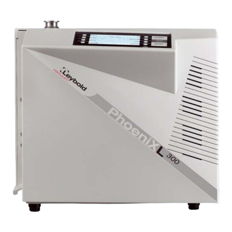
LEYBOLD PhoeniXL300 dry User manual

LEYBOLD

LEYBOLD PhoeniXL300 dry User manual

LEYBOLD 141 00 Release Note

LEYBOLD

LEYBOLD 141 00 Release Note

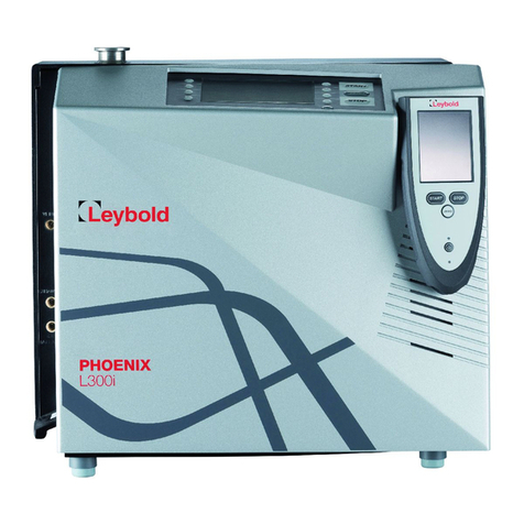
LEYBOLD PHOENIX L300i User manual

LEYBOLD

LEYBOLD PHOENIX L300i User manual

Popular Security Sensor manuals by other brands

SGB DLR-P manual

SGB

SGB DLR-P manual

GUARDEON G-OP-SCPIR-K Installation and use manual

GUARDEON

GUARDEON G-OP-SCPIR-K Installation and use manual

SkyLink WD-103 Guide User instructions

SkyLink

SkyLink WD-103 Guide User instructions

STEINEL PROFESSIONAL IS 3360 manual

STEINEL PROFESSIONAL

STEINEL PROFESSIONAL IS 3360 manual

ABB Busch Watchdog Prasenz EIB 6131-102-500... manual

ABB

ABB Busch Watchdog Prasenz EIB 6131-102-500... manual

Fluke 26500090 Technical data

Fluke

Fluke 26500090 Technical data

Petzl Verso TECHNICAL NOTICE

Petzl

Petzl Verso TECHNICAL NOTICE

AJAX DualCurtain Outdoor user manual

AJAX

AJAX DualCurtain Outdoor user manual

Makita CV100D instruction manual

Makita

Makita CV100D instruction manual

Radiodetection RD5100 S user guide

Radiodetection

Radiodetection RD5100 S user guide

NOYAFA NF-816 instruction manual

NOYAFA

NOYAFA NF-816 instruction manual

Johnson Controls LC-200S installation instructions

Johnson Controls

Johnson Controls LC-200S installation instructions

Argus Security V350 quick start guide

Argus Security

Argus Security V350 quick start guide

MWf DIGGER 800-ULTRA user manual

MWf

MWf DIGGER 800-ULTRA user manual

Busch-Jaeger Busch-Watchdog 280 ProfessionalLINE installation instructions

Busch-Jaeger

Busch-Jaeger Busch-Watchdog 280 ProfessionalLINE installation instructions

LEGRAND Celiane 670 92 manual

LEGRAND

LEGRAND Celiane 670 92 manual

Apollo Smoke Detector XP95 Installation & maintenance guide

Apollo

Apollo Smoke Detector XP95 Installation & maintenance guide

Hytronik HIM38/RF Installation and instruction manual

Hytronik

Hytronik HIM38/RF Installation and instruction manual

manuals.online logo
manuals.online logoBrands
  • About & Mission
  • Contact us
  • Privacy Policy
  • Terms and Conditions

Copyright 2025 Manuals.Online. All Rights Reserved.