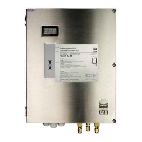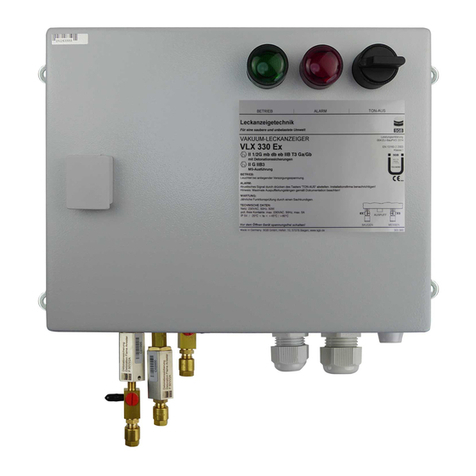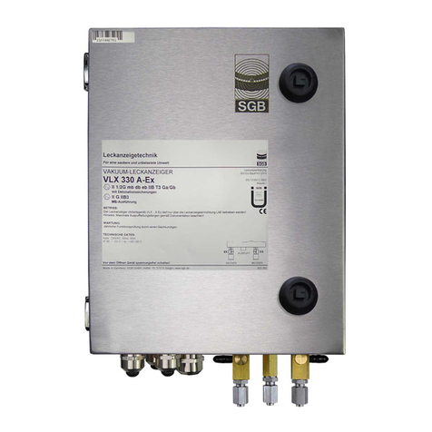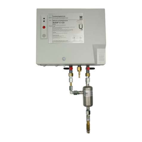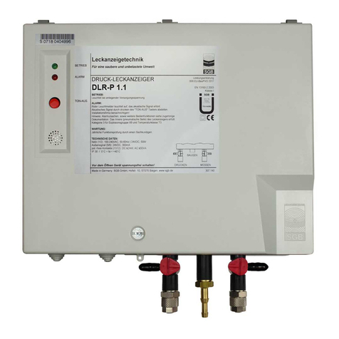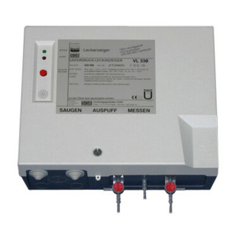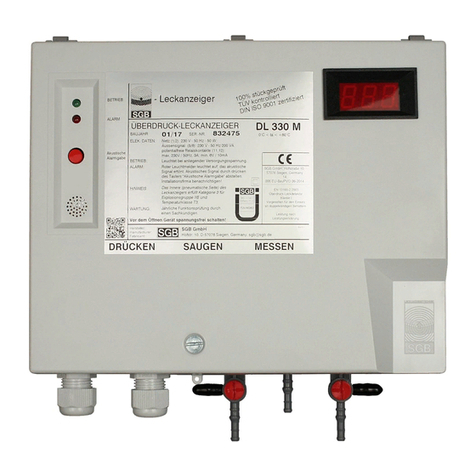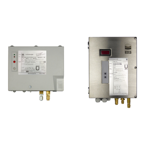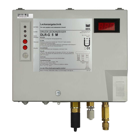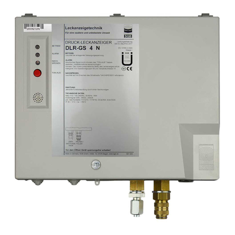
OVERPRESSURE LEAK DETECTOR DLR-P ..
DLR-
P ..
(4) Check the test valve at the end of the interstitial space away from the leak detector for
tightness and check that it is free of dirt – clean as required.
(5) Test for free passage of air through the interstitial space (section 6.4.2)
(6) Test the switching values with a testing device (section 6.4.3). Alternatively: test the
switching values without a testing device (section 6.4.3)
(7) Check the overpressure valve (section 6.4.5)
(8) Tightness test (section 6.4.6)
(9) Set up the equipment ready for operation (section 6.4.7)
(10) Completion of a test report by the qualified person, with confirmation of functional and
operational safety and reliability.
(11) Before starting work, we recommend performing the leak test of the system (which is
integrated in the leak detector) as described in section 3.5.2, in order to gain an impression
of the condition of the system.
6.4.2 Test for free passage of air through the interstitial space (see P-078 000)
(1) If several interstitial spaces are connected then each interstitial space should be tested
individually for free passage.
(2) If several interstitial spaces are connected via a mainfold with a shut-off device then all of
the shut-off valves of the manifold should be closed.
(The pressure and measuring lines are combined underneath the leak detector).
(3) Connect a gauge to the three-way cock 21 and set it to position “III”.
(4) Open the shutoff device in the manifold of the interstitial space which is to be tested, then
open the test valve at the end away from the leak detector.
IMPORTANT NOTE: Maintenance work and functional tests must only be performed by
qualified persons.
(5) Observe any pressure loss on the measuring instrument. If no pressure loss takes place,
locate and rectify the cause.
(6) Close the test valve of the pipe and then close the shut-off valve opened in step (4).
(7) Repeat steps (4) to (7) for every other pipe.
(8) Set the three-way cock 21 to position "I" and disconnect the gauge.
(9) Open all shut-off valves on the manifold with the pipe connected.
6.4.3 Test the switching values with a testing device (see P-115 395)
(1) Connect a testing device to the free connection port on the three-way cocks 20 and 21
(insert hose clips). Set both cocks to position "II".
(2) Connect the gauge to the test device.
(3) Close the needle valve (testing device) – pressure is then built up on top of the operating
pressure.
(4) Vent via the needle valve, determine the switching values for "Pump ON" and "Alarm ON"
(visual and audible), write the values down.
22/01/2009 - 10 -


