manuals.online logo
Brands
  1. Home
  2. •
  3. Brands
  4. •
  5. Apollo
  6. •
  7. Security Sensor
  8. •
  9. Apollo Smoke Detector XP95 Operating and safety instructions

Apollo Smoke Detector XP95 Operating and safety instructions

XP95 Triple IR Flame Detector
Installation & Maintenance Guide
General
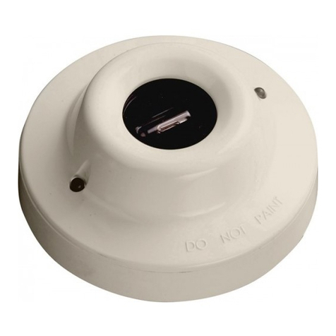
The XP95 Triple Infra-red (IR) Flame Detectors, part no 55000-020 and 55000-021 are
designed for use where open flaming fires may be expected. They are sensitive to low-
frequency, flickering infra-red radiation emitted by flames during combustion. False alarms
due to such factors as flickering sunlight are avoided by a combination of filters and signal
processing techniques.
Response to Flames
In quiescent condition, ie, in the absence of a flame, the detector returns an analogue
value of 25. When a flame is visible, the detector signals an alarm by increasing the ana-
logue value returned to 55, usually within 1.5 seconds. The analogue value may continue to
rise until it reaches a pre-set maximum of 64.
In the alarm state the XP95 Flame Detector latches for 20 seconds, with the analogue value
decreasing to 25 once the flame is no longer detected.
Electrical Considerations
The XP95 IR Flame Detector is loop powered and needs no external supply. It is connected
to a control panel using either the XP95 or Discovery protocol. A remote LED alarm indicator
may be connected to the flame detector.
Sensor Window Contamination
It is important to keep the sensor window clean and checks should be carried out at
regular intervals–determined locally according to the type and degree of contamination
encountered–to ensure optimal performance of the flame detector. Although flames can
be detected when the window is contaminated, there may be a reduction of sensitivity as
shown in the table overleaf.
It is recommended that the flame detector is disabled when the window is being cleaned.
Technical Data
Supply voltage 14–28V DC
Quiescent current 2.2mA
Alarm current 4.2mA
Switch-on surge current 30mA (peak) for 15mS
Power-up time 4 seconds
Remote LED voltage 0–28V DC
Remote LED current limited to 2mA
Fire alarm threshold Analogue value 55 returned after 10Hz flame
flicker for 1.5 seconds
Operating range 25m for 0.1m² n-heptane fire
35m for 0.2m² n-heptane fire
45m for 0.4m² n-heptane fire
Field of view/angle of reception 90° Cone
Operating temperature –10°C to +55°C
Storage temperature –20°C to +65°C
Relative humidity 95% (no condensation)
IP rating 65
Housing material Die cast zinc alloy (ZA 12)
Size and weight 142 x 108 x 82mm, 2 kg
Cable gland entries 2 x 20mm
Approval and Regulatory Information
0832 010an/13 14 CD0006/FLAME EN54-10 Flame Detectors - Point Detectors
010an/14
Additional Equipment
Flame detector weathershield, part no 29600-206
Flame detector weathershield for flameproof version, part no 29600-228
Flame sensor test unit, part no 29600-226
Flame detector bracket, part no 29600-203
PP2271/Issue 3
8 1
© Apollo Fire Detectors Limited 2014
36 Brookside Road, Havant, Hants, PO9 1JR, UK
Tel +44 (0) 23 9249 2412 Fax +44 (0) 23 9249 2754
www.apollo-fire.co.uk
Applications for Flame Detectors
Flame detectors are used when detection is required to be unaffected by convection cur-
rents, draughts or wind; tolerant of fumes, vapours, steam, dust and mist; responsive to a
flame more than 25m away and fast reacting.
Typical applications examples are:
• agriculture – grain and malt processing, animal feed manufacture
• aircraft hangars
• automotive industry – spray booths, parts manufacture
• chipboard and MDF manufacture
• power plants
• printing
• transformer stations
Applications and locations to avoid:
• ambient temperatures above 55°C
• close proximity to cell phone and CB transmitters
• sunlight falling directly onto IR optics
• exposure to severe rain and ice
• flickering or moving hot objects
• flood or spot lighting falling directly on IR optics
• large amounts of flickering reflections
• large IR sources above 200°C – heaters, burners, flare stacks
• microwave ovens and dryers
• RF heaters
• obstructions to field of view
Table 1 Sensor window contamination
Contaminant Typical percentage of
normal response
Water spray 75
Steam 75
Smoke 75
Oil film 86
Salt water film 86
Dry salt deposits 86
Functional Testing
When polled by a compatible panel or test set, the flame detector, in quiescent condition,
should return an analogue value of 25 nad input bits set to ‘0’.
If output bit 2 is set to logic 1 on two or more consecutive pollings, the red ‘FIRE’ LED on the
flame detector will illuminate.
If output bit 1 is set to 1 on two or more consecutive pollings the flame detector will perform
a self test. It does this by causing internal LEDs to flicker in the field of view of the flame
detector, thus simulating the behaviour of flames.
If output bit 0 is set to 1 on two or more consecutive pollings the flame detector will switch
on a remote LED.
Finally, provided it is safe to do so, carry out a flame test using a flickering flame source,
such as a portable bunsen burner. A still, non-flickering flame will not produce a response
from the detector.
Maintenance Guide
The flame detector is designed to give years of trouble-free operation with minimal atten-
tion. However the periodic maintenance steps listed below are essential to maintain reli-
able fire protection.
1. Inform all appropriate personnel of intention to work on the flame detector.
2. Disable any automatic systems that may be activated by the flame detector if not
required as part of the maintenance check.
Alarms Extinguishers Control
Audio/Visual Gas systems Plant stops
Auto diallers Water sprays Dampers/doors
3. Check that the flame detector’s control panel is functioning correctly and shows no
faults.
4. Inspect the detector viewing window for any build-up of dust or other contaminants
on the optical surface. If necessary clean the optical surface with a cotton wipe wet with
commercial liquid glass cleaner. Rinse with clean water and dry with a clean cloth.
The detector specification for performance is with a clean optical sensor window. Con-
taminants like dust, oil and paint will reduce sensitivity.
5. Ensure the detector still has a clear line of sight of the area it is protecting and no obsta-
cles obstruct its view.
6. Check that the detector is securely fitted.
7. Visually check the exterior of the detector for any mechanical or corrosive damage.
8. Test the operation of the detector with either a portable flame sensor test unit or if practi-
cal a flickering yellow flame.
9. Reinstate any automatic system disabled during maintenance.
10. Inform all appropriate personnel on completion of the maintenance work and if neces-
sary record this work.
2 7
6 3
Fig 4 Flame detector wiring connections
Quantities Required and Positioning of Detectors
The number of detectors required and their positioning depends on:
• the anticipated size of the flame
• the distance of the flame from the detector
• the angle of view of the flame detector
The XP95 flame detector is designed to operate to Class 1 performance as defined in EN54:
Part 10. The detector will, therefore, detect a yellow flickering flame of approximately 0.1m²
or a clear flame of 0.25m² at 25m.
In fact, the flame detector will detect fires at distances of up to 40 metres, but the flame size
at such distances needs to be proportionally greater in order to be sure of reliable detec-
tion. Thus the yellow flickering flame that can be detected at 25m, provided that its size is
not less than 0.1m², will have to be 0.4m² in order to be detected at 40 metres. In a rectan-
gular room the distance from the flame detector to the fire is calculated by the formula:
L² + W² + H²
In the example shown in Fig 1 the room in which the flame detector is to be installed meas-
ures 20m x 10m x 5m; the distance from the detector to the flame will therefore be:
20² + 10² + 5²
=22.9m
Fig 3 Mounting plate, supplied with detector, and optional bracket, part no 29600-203
The adjustable mounting bracket is used wherever it is necessary to adjust the viewing
angle up or down or left to right. It has two fixing holes of 6.35mm diameter at 58mm
centres.
Flame detectors should be fitted to solid walls or to rigid constructions that do not move
and are not subject to vibration.
Wiring
The flame detector has five connections: Line 1, Line 2, +Remote, –Remote and functional
earth/screen. The connections are accessed by removing the front plate of the flame
detector. The cable is passed through the gland at the base of the detector. See Fig 4 for
connection diagram.
L2+ L1- R+ R-
Fig 1 Calculation of distance from detector to flame
Height
Width
Length
Terminal Descriptions
1 +L2 +Line IN and OUT Terminals 6 to 8 are not used
2 –L1 –Line IN and OUT
3 +R +Remote LED
4 –R –Remote LED
5 SCREEN Functional Earth/Screen (Isolated)
4 5
Address Setting
Before installing the flame detector it is necessary to set the address using the DIL switch,
which is accessed by removing the front cover, using a 5mm hexagonal key. 7 segments of
the switch are set to 0 or 1, using a small screwdriver or similar tool.
A complete list of address settings is shown in the following table.
DIL switch DIL switch DIL switch DIL switch DIL switch
setting setting setting setting setting
addr 1234567 addr 1234567 addr 1234567 addr 1234567 addr 1234567
1 1000000 11 1101000 21 1010100 31 1111100 41 1001010
2 0100000 12 0011000 22 0110100 32 0000010 42 0101010
3 1100000 13 1011000 23 1110100 33 1000010 43 1101010
4 0010000 14 0111000 24 0001100 34 0100010 44 0011010
5 1010000 15 1111000 25 1001100 35 1100010 45 1011010
6 0110000 16 0000100 26 0101100 36 0010010 46 0111010
7 1110000 17 1000100 27 1101100 37 1010010 47 1111010
8 0001000 18 0100100 28 0011100 38 0110010 48 0000110
9 1001000 19 1100100 29 1011100 39 1110010 49 1000110
10 0101000 20 0010100 30 0111100 40 0001010 50 0100110
51 1100110 61 1011110 71 1110001 81 1000101 91 1101101
52 0010110 62 0111110 72 0001001 82 0100101 92 0011101
53 1010110 63 1111110 73 1001001 83 1100101 93 1011101
54 0110110 64 0000001 74 0101001 84 0010101 94 0111101
55 1110110 65 1000001 75 1101001 85 1010101 95 1111101
56 0001110 66 0100001 76 0011001 86 0110101 96 0000011
57 1001110 67 1100001 77 1011001 87 1110101 97 1000011
58 0101110 68 0010001 78 0111001 88 0001101 98 0100011
59 1101110 69 1010001 79 1111001 89 1001101 99 1100011
60 0011110 70 0110001 80 0000101 90 0101101 100 0010011
101 1010011 106 0101011 111 1111011 116 0010111 121 1001111
102 0110011 107 1101011 112 0000111 117 1010111 122 0101111
103 1110011 108 0011011 113 1000111 118 0110111 123 1101111
104 0001011 109 1011011 114 0100111 119 1110111 124 0011111
105 1001011 110 0111011 115 1100111 120 0001111 125 1011111
126 0111111
Table 2 DIL switch address settings
We recommend that the address be set before the flame detector is mounted on the wall.
Sensitivity Setting
The eighth segment of the DIL switch referred to in the previous section is used to set the
sensitivity of the flame detector to class 1 or class 3. For most practical purposes the switch
should be set to class 1, the sensitivity required to detect flames as described in the section
‘Quantities required and positioning of detectors’.
In exceptional cases the flame detector may be set to class 3 operation in order to avoid
nuisance alarms being caused by radiation sources that are close to the detector and
cannot be moved.
To set the DIL switch to class 1, switch to position ‘1’. To set to class 3, switch to position ‘0’.
Installation
The flame detector is mounted using either the mounting plate, which is supplied with the
detector, or the adjustable mounting bracket, part no 29600-203, which is bolted to the
mounting plate.
The standard mounting plate (supplied) is used for horizontal viewing, eg, along corridors or
along the length of industrial processes or vertical viewing inside fume cupboards or over
hoppers. It has two fixing holes of 8.5mm diameter at 74mm centres.
The flame detector should be positioned at the perimeter of the room, pointing directly at
the area of the anticipated flame or at the centre of the area to be protected. If the detec-
tor cannot ‘see’ the whole of the area to be protected, one or more additional detectors
may be required.
The flame detector is not affected by normal light sources but should be positioned so that
sunlight does not fall directly onto the viewing window.
Loop Design
The XP95 flame detector is powered from the loop; it draws 2.2mA in quiescent state and
4.2mA in alarm. In order to determine the number of flame detectors that can be con-
nected to a given loop, please refer to the Loop Calculation program, which can be
downloaded from the Apollo website or requested from Apollo’s Technical Sales depart-
ment as a CD.
The flame detector has an angle of view of approximately 90°, as shown in the diagram
below.
Fig 2 Angle of view of XP95 Flame Detector
n
n
n
n
n
n  





MÁFLAMESEEN
ATMINSTRAIGHTLINE
FROMFLAMEDETECTOR
MÁFLAMESEEN
ATMINSTRAIGHTLINE
FROMFLAMEDETECTOR
MÁFLAMENOTSEEN
ATMSINCEITISNOT
INTHEFIELDOFVIEWOF
THEFLAMEDETECTOR
M M
CENTRELINEOFDETECTOR DETECTIONOFMÁFLAME
DETECTIONOFMÁFLAME
© Apollo Fire Detectors Limited 2000-2005/RHD

Other manuals for Smoke Detector XP95

8

Other Apollo Security Sensor manuals

Apollo XP95A Series User manual

Apollo

Apollo XP95A Series User manual

Apollo XP95A Series User manual

Apollo

Apollo XP95A Series User manual

Apollo XPander User manual

Apollo

Apollo XPander User manual

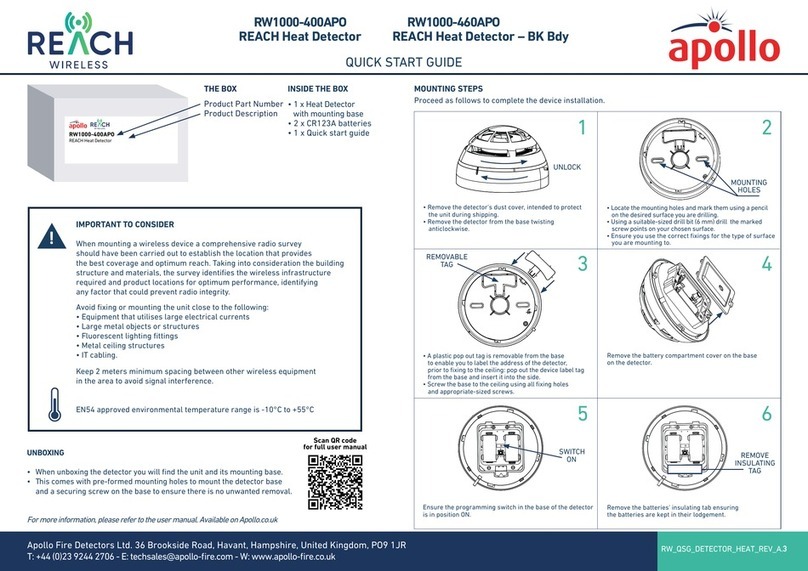
Apollo REACH RW1000-460APO User manual

Apollo

Apollo REACH RW1000-460APO User manual

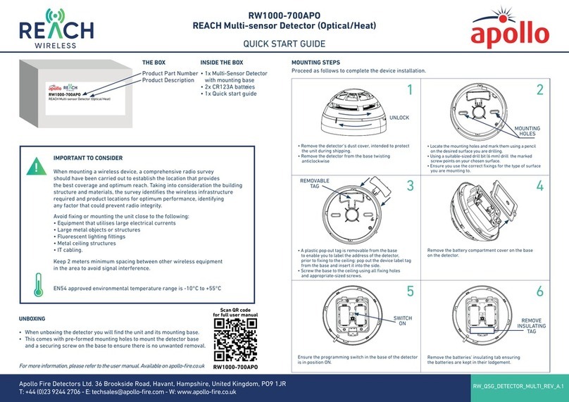
Apollo REACH WIRELESS RW1000-700APO User manual

Apollo

Apollo REACH WIRELESS RW1000-700APO User manual

Apollo ORB-OH-13001-APO User manual

Apollo

Apollo ORB-OH-13001-APO User manual

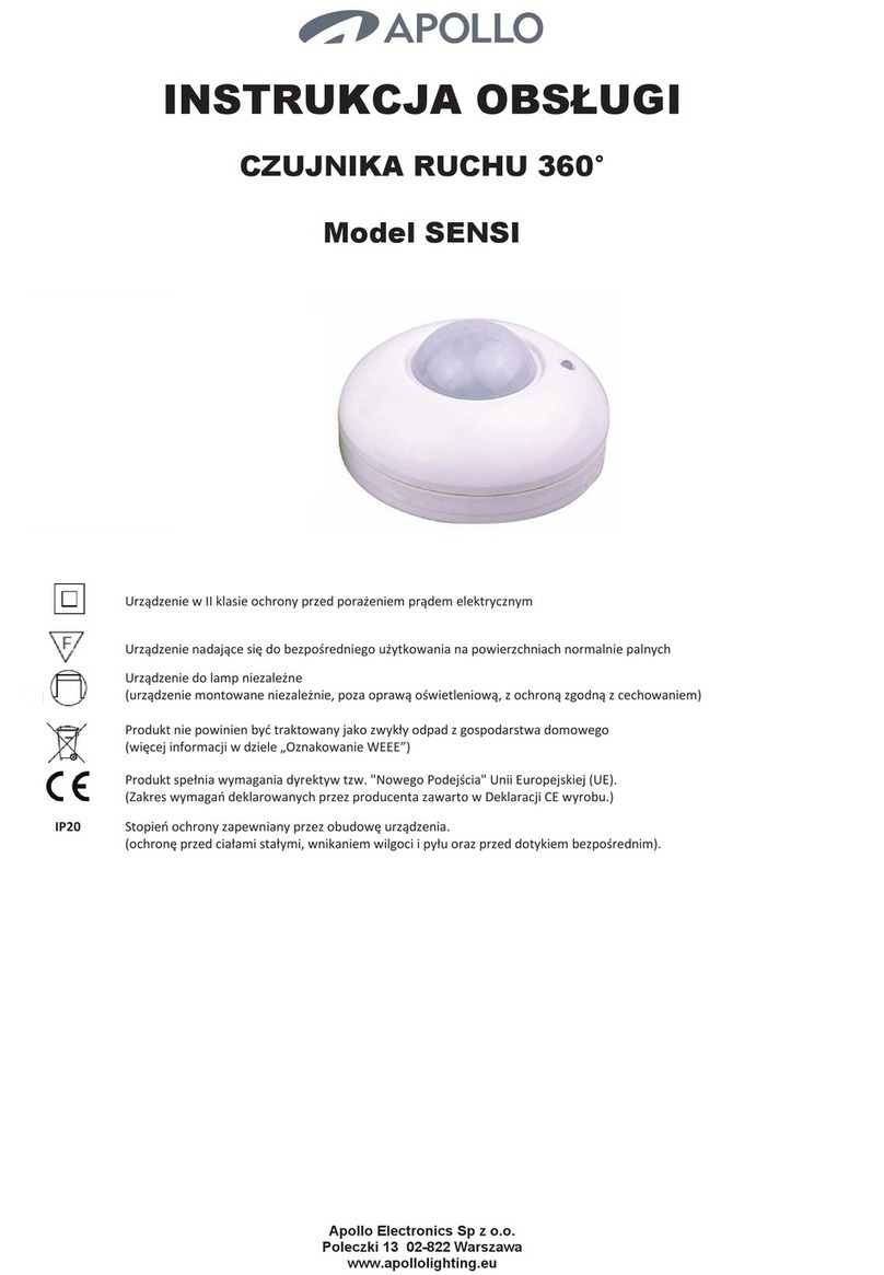
Apollo SENSI User manual

Apollo

Apollo SENSI User manual

Apollo 58000-300APO User manual

Apollo

Apollo 58000-300APO User manual

Apollo 55000-268 User manual

Apollo

Apollo 55000-268 User manual

Apollo 55000-268 User manual

Apollo

Apollo 55000-268 User manual

Apollo XP95 series User manual

Apollo

Apollo XP95 series User manual

Apollo XPA-CB-11170-APO User manual

Apollo

Apollo XPA-CB-11170-APO User manual

Apollo ORBIS ORB-OH-13003-APO User manual

Apollo

Apollo ORBIS ORB-OH-13003-APO User manual

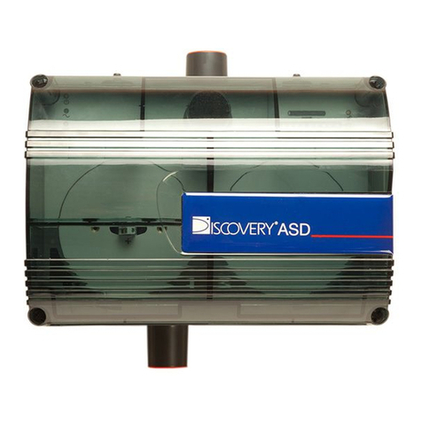
Apollo Discovery ASD-1 User manual

Apollo

Apollo Discovery ASD-1 User manual

Apollo SA7100-100APO User manual

Apollo

Apollo SA7100-100APO User manual

Apollo XP95A Series User manual

Apollo

Apollo XP95A Series User manual

Apollo RoadRunner User manual

Apollo

Apollo RoadRunner User manual

Apollo XPander XPA-CB-12034-APO User manual

Apollo

Apollo XPander XPA-CB-12034-APO User manual

Apollo 65 Series User manual

Apollo

Apollo 65 Series User manual

Apollo Smoke Detector XP95 User manual

Apollo

Apollo Smoke Detector XP95 User manual

Popular Security Sensor manuals by other brands

Atal AT-VLC-ND-A2-RS user manual

Atal

Atal AT-VLC-ND-A2-RS user manual

SWARCO MVAS Setup guide

SWARCO

SWARCO MVAS Setup guide

Waeco Multi Gas operating manual

Waeco

Waeco Multi Gas operating manual

Niko 351-25458 manual

Niko

Niko 351-25458 manual

Acroprint timeQplus TQ600 user manual

Acroprint

Acroprint timeQplus TQ600 user manual

ComSonics QAM Sniffer Quick reference guide

ComSonics

ComSonics QAM Sniffer Quick reference guide

Bosch AVENAR detector4000 user manual

Bosch

Bosch AVENAR detector4000 user manual

Inventronics QBM D4I LS HB manual

Inventronics

Inventronics QBM D4I LS HB manual

Satel AOCD-260 manual

Satel

Satel AOCD-260 manual

LynRus Aut-O-Loc 3 installation instructions

LynRus

LynRus Aut-O-Loc 3 installation instructions

Inficon WHISPER operating manual

Inficon

Inficon WHISPER operating manual

SENKO SP12C7 operating manual

SENKO

SENKO SP12C7 operating manual

REED R9200 instruction manual

REED

REED R9200 instruction manual

Peak PCAN-GPS FD user manual

Peak

Peak PCAN-GPS FD user manual

Metrotech 9800XT SFL2 Series Operation manual

Metrotech

Metrotech 9800XT SFL2 Series Operation manual

Winland BZ-1 instruction manual

Winland

Winland BZ-1 instruction manual

Emerson Rosemount CT4215 Reference manual

Emerson

Emerson Rosemount CT4215 Reference manual

Manostar EMD8A066 instruction manual

Manostar

Manostar EMD8A066 instruction manual

manuals.online logo
manuals.online logoBrands
  • About & Mission
  • Contact us
  • Privacy Policy
  • Terms and Conditions

Copyright 2025 Manuals.Online. All Rights Reserved.