INCONVENIENTI CAUSE RIMEDI
Mancanza di acqua addolcita
fra due rigenerazioni
Rigenerazione non corretta
Ripetere la rigenerazione verificando
che venga utilizzata la giusta quantità
di sale
Resine inquinate Lavare o sostituire le resine
Errata programmazione quantità di sale Verificare e riprogrammare
Vite miscelatrice troppo avvitata Svitare la vite completamente
e provare la durezza dell’acqua
By-pass aperto Chiudere by-pass
Scarico ostruito Liberare lo scarico
Mancata aspirazione salamoia
Pressione di alimento insufficiente Assicurare almeno 1,4 bar
Tubazione di scarico ostruita Assicurare lo scarico libero
Iniettore ostruito Pulire iniettore
Iniettore difettoso Sostituire
Valvola n°2 bloccata in posizione aperta Eliminare le cause del blocco
Tenuta non stagna della serie valvole Sostituire tutta la serie valvole
Il tino salamoia si riempie troppo
La valvola n°1 resta aperta
Azionare manualmente la valvola
stessa per rimuovere l’impurità
che lo blocca
Velocità di riempimento non controllata Smontare e pulire il regolatore salamoia
La valvola n°2 non resta chiusa
durante l’aspirazione salamoia
Azionarla manualmente per
rimuovere l’impurità che la blocca
e rinforzarla con una 2° molla
Aspirazione d’aria nel tubo di
collegamento al tino salamoia Verifica dei raccordi e del tubo
Il tubo aspirazione salamoia non
pesca in fondo all’addolcitore
Riposizionare la parte finale
inferiore del tubo azzurro col filtro
in fondo all’addolcitore
Iniettore ostruito o difettoso Pulire o sostituire iniettore
L’addolcitore consuma più o meno
sale rispetto a quanto previsto
Errore di regolazione del regolatore
salamoia Rifare regolazione salamoia
Aspirazione salamoia intermittente
o irregolare
Pressione di alimento insufficiente Assicurare almeno 1,4 bar
Iniettore difettoso Sostituire iniettore
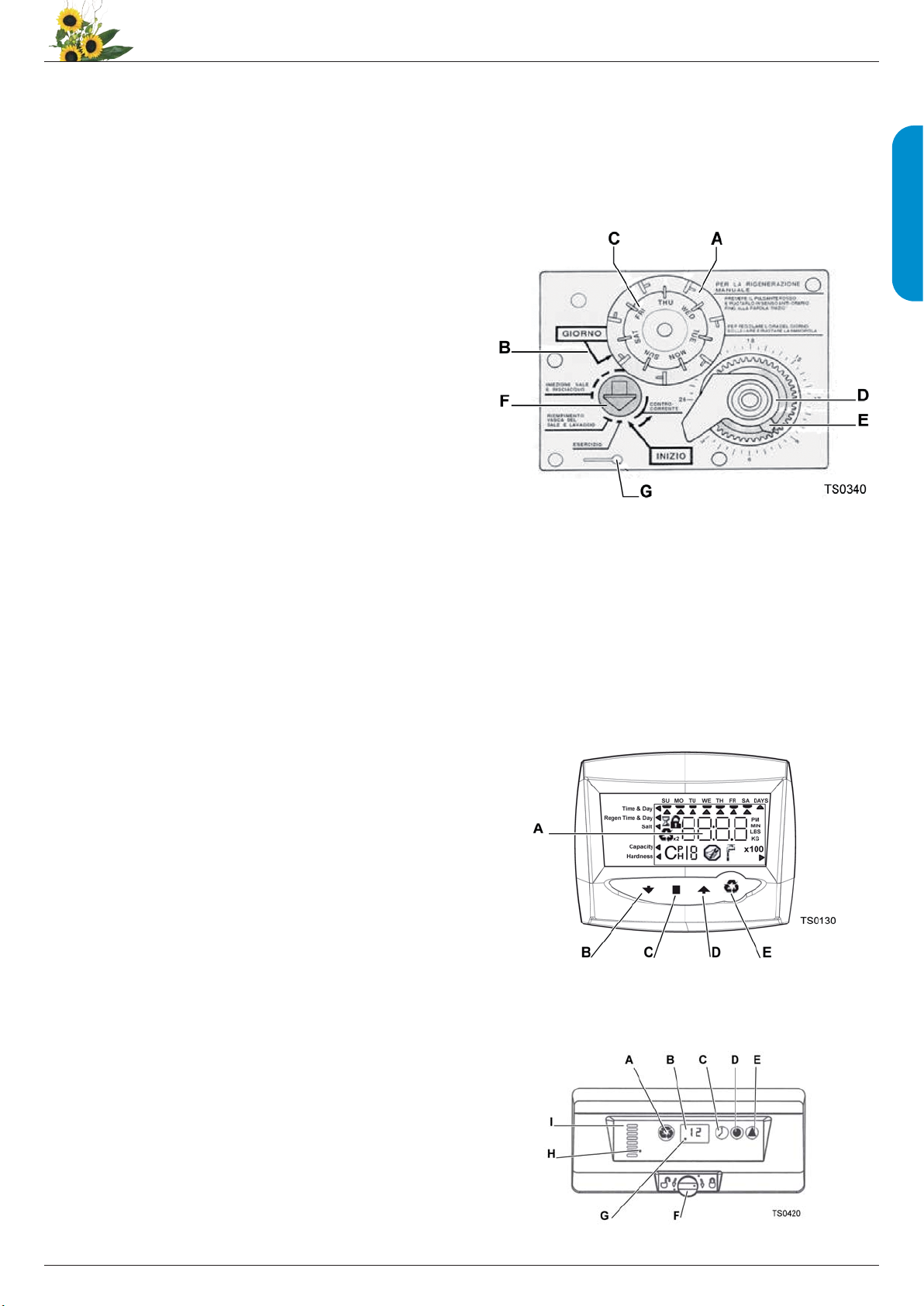
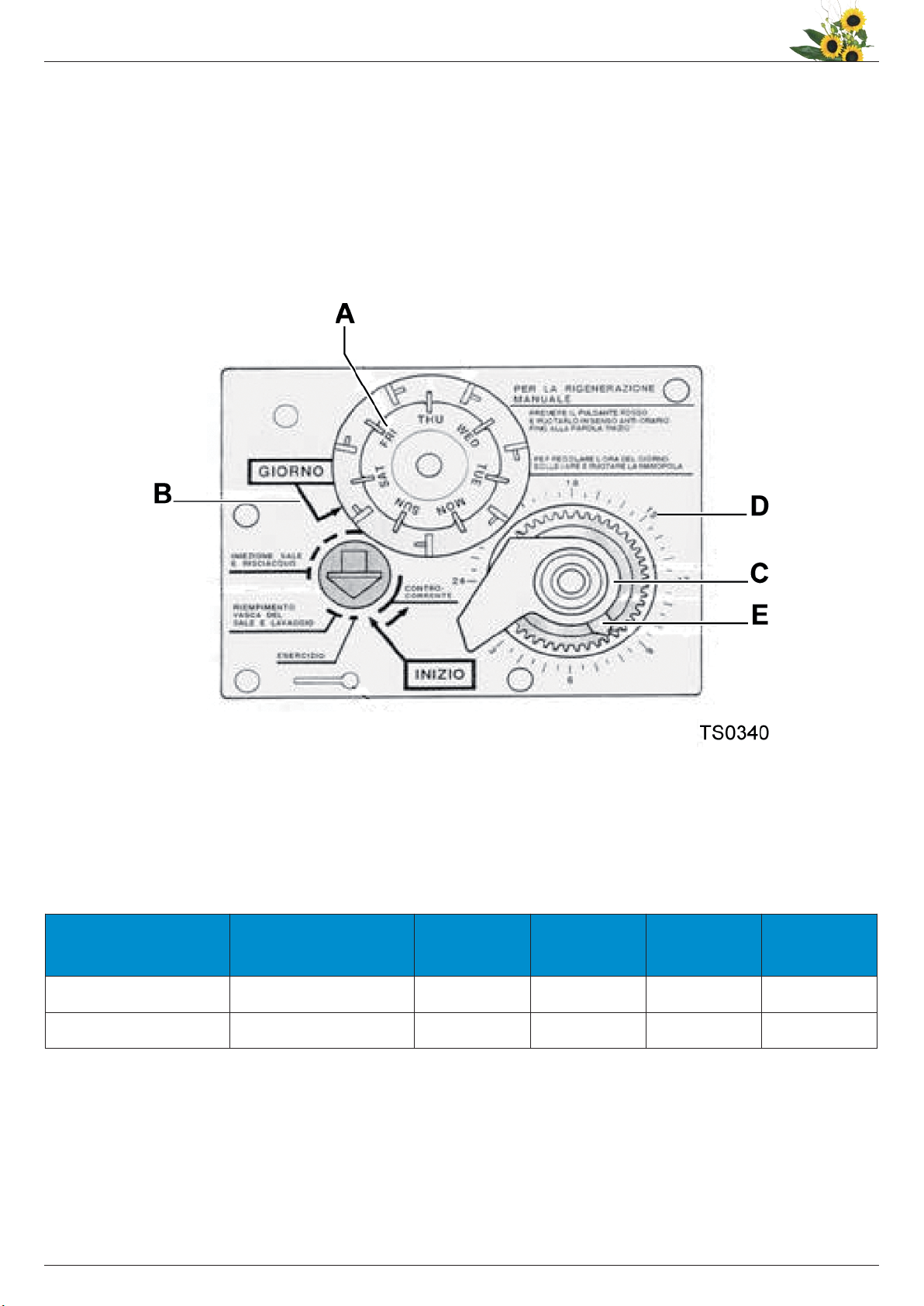
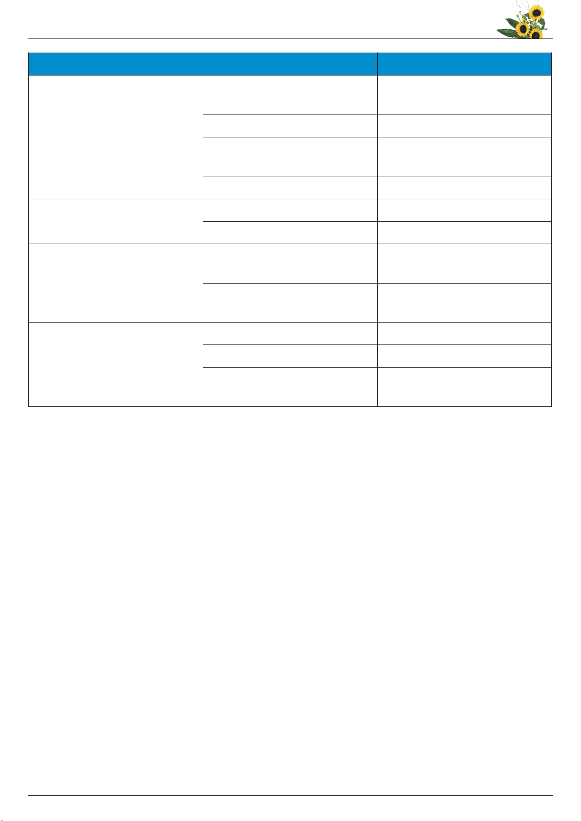
Addolcitore MATIC con testata cronometrica AUTOTROL 255/440i
7
ITALIANO